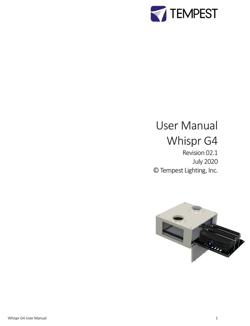
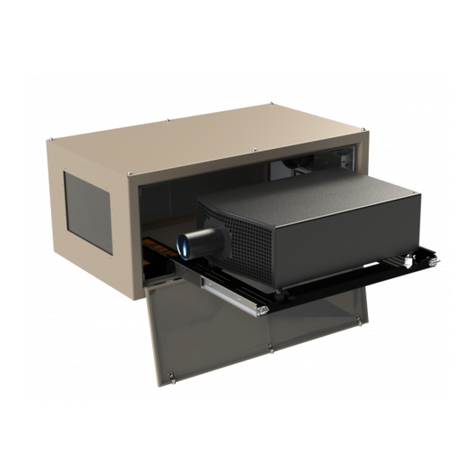
Tempest Thunder 6600 User manual

Thunder Enclosure User Manual page 1
User Manual
Thunder Lighting Enclosures
Revision 2.1
October 2018
© Tempest Lighting, Inc.

Thunder Enclosure User Manual page 2
Contents
1 Introduction...........................................................................................................................................5
2 Installation.............................................................................................................................................6
Planning......................................................................................................................................................7
Mounting the Thunder Enclosure..............................................................................................................7
Tempest XYZ Mount.................................................................................................................................10
3 Wiring...................................................................................................................................................12
Electrical Preparation ...............................................................................................................................12
Connect AC Wiring to MiniDEC Controller ..............................................................................................13
4 Mounting the Luminaire......................................................................................................................15
5 Connect Luminaire power and DMX ...................................................................................................17
6 Operation.............................................................................................................................................18
7 Routine Maintenance...........................................................................................................................19
8 Troubleshooting..................................................................................................................................20
9 Limited Warranty .................................................................................................................................21
10 Tempest Product Support...............................................................................................................23

Thunder Enclosure User Manual page 3
CERTIFICATE AND DECLARATION OF CONFORMITY FOR CE MARKING
Tempest Lighting, Inc.
11845 Wicks Street, Sun Valley, CA 91352, USA
www.tempestlighting.com
Tempest Lighting, Inc. declares that their:
Thunder Lighting Enclosure Series 6xxx.xxx
complies with the Essential Requirements of the following EU Directives:
Low Voltage Directive 2006/95/EC Test Report 60065-6600-10
Electromagnetic Compatibility Directive 2004/108/EC Test Report 61000-6600-12
and further conforms with the following EU Harmonized Standards:
EN 60065 : 2002 Test Report 60065-6600-10
EN 60529:2001-2002 Test Report 60529-6600-11
EN 61000-6-3:2007+A1:2011 Test Report 61000-6600-12
EN61000-6-1:2007 Test Report 61000-6600-12
EN55015:2006+A2:2009 Test Report 61000-6600-12
Dated: 1st March 2013
Position of signatory: President
Name of Signatory: Tim Burnham
Signed below:
on behalf of Tempest Lighting, Inc.
Dated: October 26th, 2009
Signature . . . . . . . . . . . . . .
Tempest Lighting Inc

Thunder Enclosure User Manual page 4
This is to certify that the following products
6600.US Thunder 6600 Enclosure
6610.US Thunder 6610 Enclosure, DEC3 Control
6650.US Thunder 6650 Scan Enclosure
6660.US Thunder 6660 Scan Enclosure, DEC3 Control
6700.US Thunder 6700 Enclosure
6710.US Thunder 6710 Enclosure, DEC3 Control
6750.US Thunder 6750 Scan Enclosure
6760.US Thunder 6760 Scan Enclosure, DEC3 Control
6800.US Thunder 6800 Enclosure
6810.US Thunder 6810 Enclosure, DEC3 Control
6850.US Thunder 6850 Scan Enclosure
6860.US Thunder 6860 Scan Enclosure, DEC 3 Control
Have been tested and approved to standards UL 508 (electrical) and UL 50 (environmental), as
NEMA 3R enclosures, for use in the United States and Canada.
This declaration is made by the manufacturer
Tempest Lighting, Inc.
11845 Wicks Street
Sun Valley, CA 91352, USA
This declaration is based on tests that were conducted on the submitted samples of the above
mentioned products.
Listing Report No. 3198609LAX-001a refers.
Dated: December 12th, 2010
Signature . . . . . . . . . . . . . .
Tempest Lighting Inc

Thunder Enclosure User Manual page 5
1Introduction
Thank you for purchasing the Thunder enclosure. It will serve you for many years, protecting your
stage spotlights and effects projectors from the elements.
Products Covered By this Manual
6690 Thunder, Rosco X-Effect
6600 Thunder
6700 Thunder Stretch
6800 Thunder X-Stretch
Using This Manual
Please read this manual in its entirety before starting work. All the information contained is
important, and should be read carefully before proceeding. Heed all warnings and advisories.
Icon Key:
Valuable information
Electrical Warning
Safety Information

Thunder Enclosure User Manual page 6
2Installation
Safety and Warnings
These warnings are for your protection. Failure to comply may result in serious injury or death.
Tempest Lighting, Inc. assumes no responsibility for damages or injury incurred by misuse or
mishandling of product.
Do not attempt to install or operate the enclosure before fully reading and understanding
this manual
Never allow anyone who has not read this manual to open the enclosure or perform
maintenance on the equipment within.
Never leave the enclosure unattended when open.
Always make sure all bolts and latches are tight and safety locks are in place after
performing any form of maintenance on the unit.
Do not open any electrical boxes until power has been shut off to all supply lines to the
enclosure (including the one powering the equipment).
Do not open the enclosure in wet weather.
Tools and Equipment
To install the enclosure, you will need the following items:
Crescent wrench
Phillips screwdriver
Terminal screwdriver
Proper wiring installation equipment (for line power and signal wiring)
Any equipment listed in the equipment manufacturer’s equipment-specific installation
directions

Thunder Enclosure User Manual page 7
Planning
Snow clearance:
Allow at least 24”/60cm clearance behind enclosure for access and ventilation.
Enclosures should be powered during daylight hours to prevent overheating under hot sun.
Warning: In most cases this installation cannot be safely completed by 1 person.
Mounting the Thunder Enclosure
The Thunder enclosure must be mounted on or under a solid structure rated for the weight of
the enclosure, the equipment inside it, and at least one person.
Snow –if installed outside in cold regions, the bottom of the Thunder enclosure must be at
least 2’ (60cm) above maximum height of any snowfall or drifting snow, subject to local
conditions. If snow is not a consideration, then enclosure may sit on the ground as long as
proper drainage is provided.
LEAVE ADEQUATE CLEARANCE BEHIND ENCLOSURE FOR WIRING AND VENTILATION
Tempest Lighting recommends the use of stainless steel mounting hardware.
MINIMUM
24”/60c
m
24”/60cm

Thunder Enclosure User Manual page 8
The Thunder enclosure is provided with a pair of Unistrut channels on the enclosure base, for
mounting to your structure. You may use standard Unistrut accessories, or purchase either of the
mounting kits available from Tempest Lighting –four kits are recommended per enclosure.
Mounting Kits
4900.MB Stainless Steel Unistrut channel nut,
bolt and washer. Four required per enclosure.
4900.MC Stainless Steel Unistrut channel nut,
bolt and pipe clamp, for pipes 1.5” (38mm) to 2”
(50mm) OD. Four required per enclosure.
4925.MC Stainless Steel Unistrut channel nut,
bolt and pipe clamp, for pipes 2” (50mm) to 2.5”
(64mm) OD. Four required per enclosure.
Mounting on a Pipe or Truss
Use two clamps to mount to a pipe, or to mount from a truss at an angle.
Use four clamps to mount parallel to a truss.

Thunder Enclosure User Manual page 9
Mounting Base-down and Base-up
All Thunder enclosures are designed to be mounted base-down, on a solid structure, using Unistrut
mounting hardware. They may also be suspended from an overhang, ceiling or truss, using the
same hardware.
It is the responsibility of the installer to ensure that all mounting points are secure and conform to
local safety regulations. Tempest Lighting Inc. accepts no responsibility for damage or injury
arising from inappropriate or unsafe installation.
Drainage
Drainage holes are provided in the top and bottom of the enclosure. The holes in the cover (top) are
plugged with 10-32 screws and sealing washers.
Important –Drainage in base-up installations:
1Remove the drainage plug screws from the cover
2Replace in the corresponding holes in the base
Enclosure shown
is a Blizzard
projector
enclosure
Thunder
mounted Base-
down –note the
orientation of
the inlet and
outlet vents
Inlet
Vent
Outlet
Vent
Inlet
Vent
Outlet
Vent
Thunder mounted Base-up
–in this case the inlet and
outlet vents are flipped
vertically, to prevent
rainwater ingress

Thunder Enclosure User Manual page 10
Tempest XYZ Mount
All Thunder enclosures may be mounted using the adjustable Tempest XYZ mount (part #
6500.XYZ). The XYZ Mount is designed to mount on the bottom of a piece of 1½” schedule 40 pipe
(48-50mm Outside Dimension). To mount on a horizontal truss or pipe, use 6500.XYZ.T.
Part #: 6500.XYZ
Adjustment Range:
Vertical: +60° to -90°
Horizontal: 360°
Roll: ± 10°
Continued/…
Spring nuts lock into
Unistrut rails on
Blizzard base
IMPORTANT
Drill a 3/8”/10mm hole through the bottom of your
vertical pole, and use this bolt and locknut to fix
the safety collar in place
Tighten this knob both
sides to lock tilt
movement
This bolt should be
just tight enough so
the projector can tilt
with a little hand
pressure.
Friction Pad ensures a
tight grip when locked
down
Tighten this knob to
lock horizontal (pan)
movement
Tighten these screws to raise this side
(roll), or loosen to lower it.
Then…
Tighten the locknuts up under the yoke to
lock the roll position.
The Safety Collar
MUST be bolted
through the bottom of
the pole, below the
yoke
YOKE
CRADLE
SAFETY
COLLAR

Thunder Enclosure User Manual page 11
Important
•Installation must conform to all local safety norms and building codes. Tempest Lighting,
Inc will accept no responsibility for incorrect or unsafe installation.
•Installer must drill the bottom of the pole and install the safety bolt provided
•The vertical pole must be securely mounted and braced to prevent movement

Thunder Enclosure User Manual page 12
3Wiring
Electrical Preparation
All electrical work must be carried out by a properly licensed electrician. Failure to observe
this point will void the factory warranty for the Tempest Enclosure and possibly the equipment
housed inside.
1. Before starting work, switch off power to the branch circuit, carefully following lockout and
tag-out procedures. Failure to do so could cause serious injury or death.
2. Your Thunder enclosure is supplied fitted with two cable entry points, for Power and DMX
signal cables.
3. The cable entries are suitable for use with standard conduit fittings. US size ½”,
international 20mm. Tempest recommends the use of flexible, outdoor-rated conduit for
the last few feet (1m) to the enclosure.
4. All junction boxes must be installed in accordance with local electrical codes and should be
located near the permanent installation of the enclosure. Each junction box requires a
length of flexible conduit, long enough to reach from the junction box to the enclosure
conduit fittings. Leave slack for positioning of enclosure, and enough space behind the
enclosure for ventilation.
5. The AC supply must be protected by a fuse or circuit breaker of a rating suitable for the
equipment inside the enclosure plus 50W
6. Thunder Enclosure Power Requirement:
9. The user may connect the fan and the equipment to the same switched supply, or run them
separately, according to need (see below).
10. Note that for temporary installation, the conduit fittings may be replaced with outdoor-
rated cable entry glands, at the user’s discretion.

Thunder Enclosure User Manual page 13
Connect AC Wiring to MiniDEC Controller
Single Feed Operation Split Feed Operation
Single Feed Wiring
Feed the controller with a single maintained supply. The light must be switched off when needed using
the lighting control system.
Thunder ships configured for single feed wiring operation.
DO NOT CONNECT SINGLE FEED WIRING TO THE OUTPUT OF A DIMMER.
Dual Feed Wiring
You may switch off the supply to the light without interfering with the cooling fan operation. Connect
feeder wires as shown, AND CUT THE COPPER LINK ON THE MiniDEC BOARD IN TWO PLACES, AS
SHOWN. Fan circuit should be maintained 24/7.
NEUTRAL
GROUND
LIVE (Fan)
LIVE (Light and Fan)
LIVE (Light)
CUT LINK 2
PLACES FOR
SPLIT FEED
OPERATION
NEUTRAL
GROUND

Thunder Enclosure User Manual page 14
MiniDEC Operation
The MiniDEC controller monitors current going to the light fixture inside the Thunder enclosure, and
also heat inside the enclosure. When it detects that the light is on and/or the internal temperature is
getting warm, MiniDEC runs the enclosure fan. For best results, enclosures must be connected to live
power at all times.
DMX Wiring
A separate conduit entry is provided for DMX wiring. Pull DMX cables into enclosure and terminate,
following instructions provided by the luminaire manufacturer.

Thunder Enclosure User Manual page 15
4Mounting the Luminaire
If the Thunder enclosure is suspended from a ceiling or overhang, this must be done by two people.
1. Place the equipment on the equipment tray. If hanging the equipment upside-down, one person
must hold the equipment in position, while another person secures it in place. Ensure that the
equipment is securely held before proceeding further.
2. For most theatrical lights, adjust the yoke to the shortest available setting before installing in the
enclosure, as shown here.
3. Move the Unistrut Channel nut into position, to line up with the fixture yoke.
4. Bolt through the yoke into the channel nut and tighten firmly in place, using the hardware
provided.

Thunder Enclosure User Manual page 16
NOTE: Mounting the Atomic Strobe in the 6660 Enclosure
The Atomic Strobe enclosure has its window on the SIDE of the enclosure, and the strobe faces
sideways, mounted on two M12 spring-bolts provided.
Adjust the position of the spring bolts in the Unistrut to correspond with two of the mounting holes in
the Atomic Strobe yoke.

Thunder Enclosure User Manual page 17
5Connect Luminaire power and DMX
1. Connect the DMX IN and OUT luminaire connections as specified by the luminaire
manufacturer
2. Connect the luminaire power cable to the IEC outlet provided on the MiniDEC controller. If
necessary, shorten the length of the luminaire power
cord and install the rewireable IEC plug provided with
your Thunder enclosure.
3. Test all luminaire functions.
4. Replace MiniDEC Cover.
5. Replace enclosure cover and secure all latched tightly.
Closing the Thunder Enclosure
The latch tension is adjusted
by turning the screw –
clockwise to tension, anti-
clockwise to loosen.
Insert a padlock in
one or more security
rings for additional
security.

Thunder Enclosure User Manual page 18
6Operation
While there are no specific operational actions required for normal use, the following points should be
kept in mind.
The enclosure should be connected to a live circuit at all times except when maintenance is being
carried out.
Unless the enclosure or equipment is undergoing routine maintenance, the enclosure should be
closed and securely latched at all times.
Only authorized personnel should open the enclosure (see maintenance warnings in the next
chapter).

Thunder Enclosure User Manual page 19
7Routine Maintenance
It is very important to perform routine maintenance on both the enclosure and the equipment inside it.
Failure to do so may reduce lifetime for both the enclosure and the equipment.
Note
Maintenance schedules depend on location and environment. The intervals given here are
general minimum guidelines. It is up to the user to judge whether maintenance should be carried out
more frequently. We recommend doing these tasks no less often than mentioned here.
Safety
As the enclosure is a powered unit with moving parts, it is necessary to keep safety in mind
while performing routine maintenance. Although maintenance can be performed while the enclosure is
powered, it is safer to carry it out with the power disconnected with proper lockout and tag out
procedures followed.
Be aware that once the enclosure has had power applied to it, the fan will start to turn. Make
sure that your hands are clear of the fan before applying power to the enclosure.
Only authorized personnel should perform maintenance on the enclosure or equipment
Do not service the unit in the rain or other adverse weather conditions (snow, sleet, high
winds, etc.).
Inspection Checklist: - Every Three (3) Months
Glass should be clean and free of cracks
Enclosure should be free of debris both inside and out
Bolts and tie-down straps should be tight
Rubber seals should be in good condition. Check seals inside and out for gaps.
Fan hould be functioning and not making excessive noise
Filters should be clean
Air Filter - Every Three (3) Months
The air filter should be removed and cleaned on a regular basis. To remove filter, pull pull it directly
out of the intake vent. The filter can be cleaned by running water from a hose and do not require any
special solution.
To reinstall, carefully push filter back into the cowl molding.
Case - As Needed
The outside of the case should be cleaned as needed. The case should be cleaned with a wet
cloth and mild detergent (if necessary). Do not use a direct spray from a hose to clean the case.
Equipment
Review the manufacturer's instructions for proper maintenance of your Luminaire. Remember,
the enclosure simply protects the equipment inside it and is not a substitute for regular maintenance.

Thunder Enclosure User Manual page 20
8Troubleshooting
This is a guide to the general symptoms, problems, and solutions that may occur during the
usage of your enclosure. However, it is important to remember that problems may occur within the
equipment itself and these must also be considered.
Equipment does not have power.
Check power supply wiring and voltage.
Fan is not spinning
Fan cords may have become disconnected. Check connections between fan and cord.
Fan may be obstructed. Shut off power to enclosure and check for obstructions. Turn power
back on to see if fan will start spinning. If fan does not turn then enclosure is not receiving power.
Turn off all power and check wiring. If the wiring is correct, contact technical support.
Equipment does not have power.
Check equipment power switch. If switch is on, check wiring and supply switch/circuit breaker.
Equipment turns on and off repeatedly over short span of time.
Check that vent areas and airways are clear. If so, ambient temperature may be too high, or
equipment may have internal problem.
Excessive water in enclosure.
Seal leak. Repair with silicone sealant, or replace seal.
This manual suits for next models
11
Table of contents
Other Tempest Enclosure manuals
