Tempest Leader SMOKE 3 User manual
1

2

3
Product references
R20.00.113
LEADER Smoke 3 600 m³ per minute-220 v-50/60 Hz
R20.00.114
LEADER Smoke 5 1320 m³ per minute-220 v-50/60 Hz
R20.00.115
LEADER Smoke 3 600 m³ per minute-115 v-50/60 Hz
R20.00.116
LEADER Smoke 5 1320 m³ per minute-115 v-60 Hz

4
1INTRODUCTION ...........................................................................................................................................5
2SAFETY INFORMATION..............................................................................................................................5
3TECHNICAL SPECIFICATIONS ..................................................................................................................8
4PRODUCT DETAILS ...................................................................................................................................10
5QUICK START .............................................................................................................................................11
5.1 Setting up .......................................................................................................................................................11
5.2 Making fog.....................................................................................................................................................11
6INSTALLATION AND SETTING UP.........................................................................................................12
6.1 Location .........................................................................................................................................................12
7AC POWER...................................................................................................................................................12
7.1 Setting up .......................................................................................................................................................13
7.2 Final checks....................................................................................................................................................13
7.3 Turning on the power.....................................................................................................................................13
8CONTROL SETTINGS ...............................................................................................................................14
8.1 Overview........................................................................................................................................................14
8.2 Setting smoke output level...........................................................................................................................14
8.3 Setting continuous operation..........................................................................................................................15
8.4 Setting the Timer............................................................................................................................................15
8.5 Resetting the machine after fluid out.............................................................................................................16
8.6 Auxiliary input...............................................................................................................................................16
9APPROVED FOG FLUID TYPES................................................................................................................17
10 BASIC SERVICE ..........................................................................................................................................18
10.1Cleaning.........................................................................................................................................................18
10.2Fuse replacement............................................................................................................................................18
11 TROUBLESHOOTING.................................................................................................................................19
12 Status messages..............................................................................................................................................19
13 WARRANTY.................................................................................................................................................22

5
1INTRODUCTION
The LEADER Smoke 3 and 5 from LEADER provide a versatile and convenient solution for fire
training. It can produce a variety of effects from and optically translucent haze to a dense ‘white out’
that very effectively simulates dense smoke for realistic firefighter training to a wide range of fog
requirements whether permanently installed or taken on the road.
The units have been designed to cope with the rigors of training with a tough out casing and rugged
water-resistant design.
The units are controlled using an advanced control panel with LCD screen can be operated on
the machine or removed and used as a remote controller. They also have an auxiliary input to allow
remote control
devices to be used with the product for maximum flexibility.
2SAFETY INFORMATION
LEADER Smoke 3 and LEADER SMOKE 5
Read the safety precautions in this manual before installing, operating or servicing
this product.
The following symbols are used to identify important safety information:
Warning! This product is not for household use. It presents risks of injury due to
electric shock, burns, falls and respiratory problems!
Read this manual before operating the machine, follow the safety precautions listed below,
and observe all warnings in this manual and printed on the machine. Use the machine only
as described in this manual and in accordance with local laws and regulations.
If you have questions about how to operate the machine safely, or if you have followed
the instructions in this manual and the machine is malfunctioning, please contact LEADER.
Danger!
Hazardous voltage.
Contact will cause electric
shock.
Danger!
Safety hazard. Risk
of personal injury
Caution!
Burn hazard.
Hot surface.
Do not touch.
Caution!
Fire hazard.

6
Preventing electric shocks
•Always ground (earth) the machine electrically.
•Use only a source of AC power that complies with local building and electrical codes,
and that has both overload and ground-fault protection.
•Before connecting the machine to power, check that the voltage indicated on the
machine’s serial label matches your local AC power
voltage. If your AC power voltage does not match, do not use the machine.
Contact LEADER for assistance.
•Before using the machine, that all power distribution equipment and cables are in
perfect condition and rated for the current requirements of all connected devices.
•If the machine or any cables connected to it are in any way damaged, defective, wet, or
show signs of overheating, stop using the machine and contact LEADER for assistance.
If the supply cord is damaged, it must be replaced by a special cord or assembly
available
from the manufacturer.
•Disconnect the machine from AC power before servicing and when not in use.
•This machine is water-resistant but not totally waterproof. Do not immerse in water or
any other liquid. Do not expose to high-pressure water jets.
•Do not spill fluid over or inside the machine. If fluid is spilled, disconnect AC power
and clean with a damp cloth. If fluid is spilled on to electronic parts, take the machine
out of service and contact LEADER for advice.
•Do not remove the covers or attempt to repair a faulty machine. Refer any service not
described in this manual to LEADER.
•Do not operate the machine if any parts are damaged, defective or missing.
•Moisture and electricity do not mix. Do not aim fog output at electrical connections or
devices.
Preventing burns and fire
•The fog produced by the machine is hot enough to cause burns when it leaves the
nozzle, and very hot droplets of fluid escape occasionally.
Keep people and objects at least 600 mm (24 in.) away from the fog output nozzle.
•Do not touch the fog output nozzle during or after use –it becomes extremely hot and
remains hot for several hours after the machine has been shut down.
•Do not attempt to bypass thermostatic switches, fluid sensors or fuses.
•Replace fuses only with ones of the type and rating specified in this manual for the
machine.
•Provide a minimum free space of 100 mm (4 in.) around the machine.
•Provide a minimum free space of 500 mm (20 in.) around fans and air vents and ensure
free and unobstructed air flow to and around the machine.
•Keep the machine at least 600 mm (24 in.) away from combustible and heat-sensitive
materials.
•Do not operate the machine if the ambient temperature (Ta) is below 5° C (41° F) or
above 40° C (104° F).
•Do not operate the machine if the relative air humidity exceeds 80%.
•Do not recycle dense smoke into the machine.

7
Preventing injuries
•Ensure that any surface on which the machine is installed can safely hold the weight of
the machine.
•Suspending the machine directly over peoples heads is not recommended. Use smoke
ducting instead.
•Do not point the smoke output directly at a person’s face or at face height.
•Do not operate the machine with missing or damaged covers or shields.
•In the event of an operating problem, stop using the machine immediately and
disconnect it from power. Do not attempt to use a machine that is obviously damaged.
•Do not modify the machine in any way not described in this manual or install other than
genuine LEADER parts.
•Refer any service operation not described in this manual to a qualified technician.
•Fog output can cause condensation. Do not point the output at smooth floors. Floors and
surfaces may become slippery. Check these frequently and wipe dry as necessary to
avoid any danger of slipping.
•Fog fluid contains food-grade glycols in solution but may present health risks if
swallowed. Do not drink it. Store it securely. If eye contact occurs, rinse with water.
If fluid is swallowed, give water and obtain medical advice.
•This appliance is not intended for use by persons (including children) with reduced
physical sensory or mental capabilities, or lack of experience and knowledge.
Preventing breathing problems
•A machine can operate safely only with the fog fluid it is designed for.
Use the machine only with fluids specified under “Approved fluid types” on page 16 or
you may cause the release of toxic gases, presenting a severe health hazard. You will
also probably damage the machine.

8
3TECHNICAL SPECIFICATIONS
All dimensions are in millimetres.
▪Robust water resistant design.
▪Integrated digital remote control.
▪Continuous micro-processor controlled output.
▪Two fluid options for different applications.
▪Soft start technology.
▪Fluid sensing system.
▪Easy external fluid hook-up.
▪Optional ducting kits.
Use only an approved LEADER fog fluid as shown on page 16.
Use of other fluid will void warranty.
▪Physical
LEADER Smoke 3
LEADER Smoke 5
Length
485 mm (19.1 in)
602 mm (23.1 in)
Width
335 mm (13.2 in)
395 mm (15.6 in)
Height
242 mm (9.6 in)
306 mm (12.1 in)
Weight.dry
11.2 Kg (24.7 ib)
17.7 Kg (39.1 ib)
Weight.filled
13.5 Kg (30.2 ib)
22.7 Kg (50.0 ib)

9
▪Performance
LEADER Smoke 3
LEADER Smoke 5
Coverage volume
660 m³ per minute
1320 m³ per minute
Fluid consumption (max)
88 ml per minute
176 ml per minute
Continuous effect output Ready time
7 minutes*
10 minutes*
*Please not the 110V units may take approximately 10% longer to reach their ready temperature.
▪Control and programming
LEADER Smoke 3
LEADER Smoke 5
Control options
Integrated digital remote control
Control parameters
Continuous or timer-controlled output
Fog
Variable output control, 0-100%
▪Structure
LEADER Smoke 3
LEADER Smoke 5
Housing
Steel and Aluminium
Colour
Yellow
Heat exchanger
1150w (thermally protected)
2000w (thermally protected)
Fluid pump
Oscillating piston, high pressure
Fluid management
Fluid out sensing, sealed for transportation
Fluid reservoir
2,5 L drop-in reservoir with
quick-connect fitting
5 L drop-in reservoir with
quick-connect fitting
External fluid control
Fluid sensing
Remote control
Integrated digital remote with 3 m cable, 3-pin XLR
▪Installation
LEADER Smoke 3
LEADER Smoke 5
Mounting
Standing
Clearance around machine
100 mm (4 in)
Orientation
Up to +/- 40° from horizontal
▪Connections
LEADER Smoke 3
LEADER Smoke 5
Remote control
3-pin locking XLR
Flimware
AVR socket
▪Electrical
LEADER Smoke 3
LEADER Smoke 5
Ac power
220 v-50/60 Hz
115 v-60 Hz
220 v-50/60 Hz
115 v-60 Hz
Current
5.3 A
8.75 A
9.2 A
15 A
Power
1200 w
1050 w
2100 w
1800 w
Main fuse
6.3 AT (slow-blow)
10 AT (slow-blow)
12.5 AT (slow-blow)
20 AT (slow-blow)
▪Thermal
LEADER Smoke 3
LEADER Smoke 5
Maximum ambient temperature (Ta max)
40° C (104° F)
Exterior surface temperature
Etat stable à 20° C (32° F), température ambiante 30° C (86° F)
Max nozzle temperature
290° C (554° F)
Minimum ambient temperature (Ta min)
5° C (41° F)
10
▪Approvals
EU Model
LEADER Smoke 3
LEADER Smoke 5
EU Safety
EN 60 335-1+A15, EN62233
EU EMC
EN 61000-6-3
EU Immunity
EN 61000-6-1
Australia/NZ (pending)
RCM
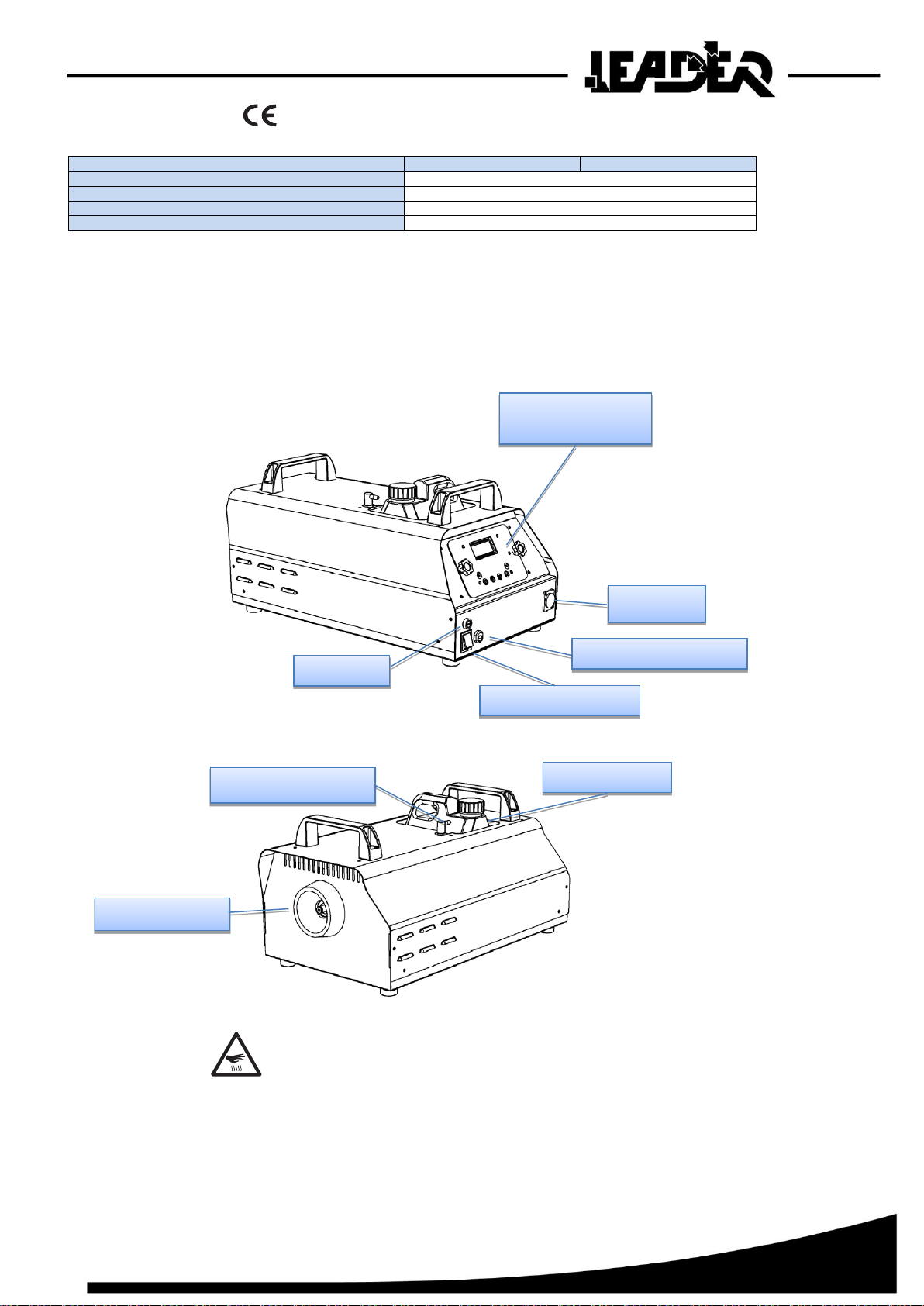
4PRODUCT DETAILS
LEADER Smoke 3 / LEADER Smoke 5
Warning!
High temperature vapour and surfaces
Fluid pipe connection
Fluid container
Integrated digital
remote control
Mains fuse
AUX input
Mains power switch
Mains power connector
Fog output nozzle
11
5QUICK START
If you are familiar with this type of product, this section will help to get you started quickly.
However, please also make the time to read the safety and servicing instructions in the remainder
of this manual.
5.1 Setting up
Locate the machine in a suitable area with nothing in front of the fog output.
Install approved LEADER fog fluid as shown on page 16.
Connect the machine to a suitably rated power source. The power requirements are:
LEADER Smoke 3 1200 W, 5.3 A / 240 V (EU)
1050 W, 8.75 A / 110 V
LEADER Smoke 5 2100 W, 9.2 A / 240 V (EU)
1800 W, 15 A / 110 V
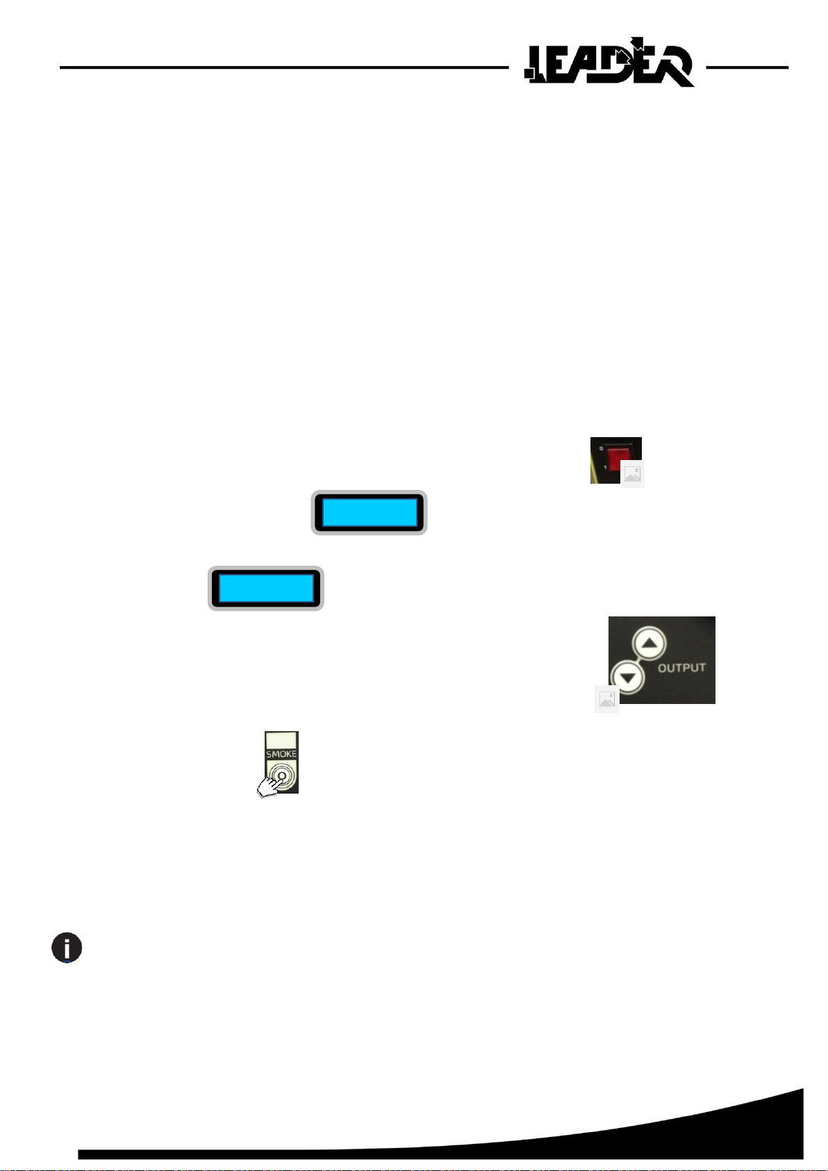
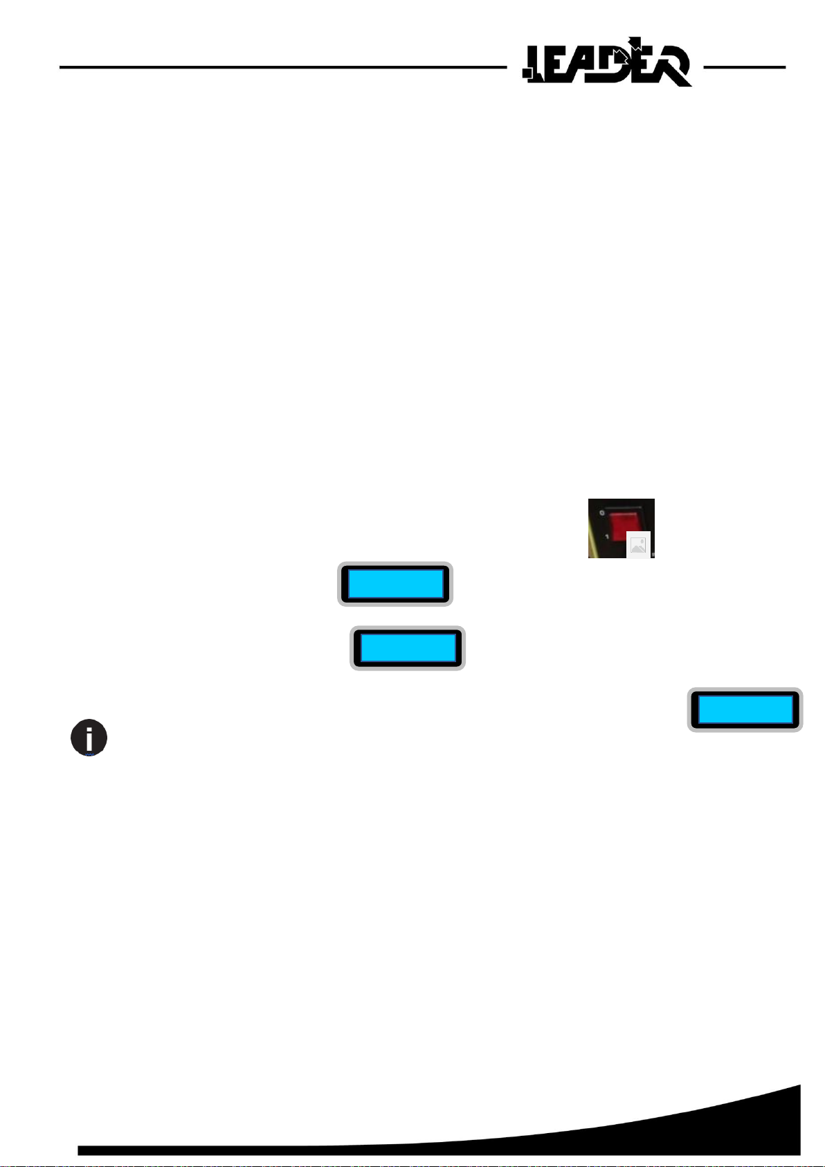
Now set the mains switch on the rear of the unit, to the ‘ON’ (I) position.
The display will show HEAT.
After about 6-8 minutes the display should show READY and the current programmed
output level %.
5.2 Making fog
If you want to adjust the fog output level press the output up/down buttons
until the display shows the desired output level.
Press the Smoke button to begin fog production.
The unit will continue to produce fog until the button is pressed again or the fluid supply is
depleted
(whichever is sooner).
If no fog is produced the first time the unit is fired after a fluid out, it may be necessary to
prime the machine. Program the output to maximum power and fire the machine until fog
is emitted.
HEAT
READY 00%
12
6INSTALLATION AND SETTING UP
DANGER! DO NOT operate the machine until you have read and observed all
the precautions listed under “Safety information” on page 4.
6.1 Location
The Trainer LEADER range of machines are designed to be located on the floor or any
surface suitable to support their weight. The machine can operate in any orientation from 45
degrees upwards to 45 degrees downwards. Steeper tilting may cause fluid leakage.
Ensure that there is at least 100mm (4 in.) clearance all-round the machine and at least
600mm (24 in.) in front of the fog output.
7AC POWER
Before using the machine, ensure that a grounding-type (earthed) power plug that fits the
local power outlets is installed on the power cable provided.
DANGER! Make sure the power plug is correctly rated:
For UE LEADER Smoke 3 and LEADER Smoke 5 models use a plug rated at 10 A
minimum.
When installing the plug, follow the plug manufacturer’s instructions and connect pins
as follows:
Yellow and green wire to ground (earth), blue wire to neutral and brown wire to live.
The table below shows some common pin identification schemes.
Before connecting the machine to power, verify that the AC supply is adequately
dimensioned for the current draw of the machine.
LEADER Smoke 3 1200 W, 5.3 A / 240 V (EU)
1050 W, 8.75 A / 110 V
LEADER Smoke 5 2100 W, 9.2 A / 240 V (EU)
1800 W, 15 A / 110 V
Check that the local AC voltage is appropriate, as indicated on the machine’s serial number
label. If your AC voltage is outside the appropriate range, do not use the machine.
Contact LEADER for assistance.
Wire
Function
Marking
Screw colour
Brown
Live
« L »
Yellow or Brass
Blue
Neutral
« N »
Silver
Green/Yellow
Earth
Green
13
7.1 Setting up
Fill the fluid tank with an approved LEADER fluid as shownon page 16.
7.2 Final checks
Before applying power to the machine, verify the following:
•The machine is safely located or installed and meets the location requirements stated on
page 11.
•The operator is familiar with, and able to comply with, the requirements for safe operation
listed on page 4.
•The fluid is one of the Approved LEADER fluids listed under “Approved fluid types”
on page 16.
•The machine is electrically grounded (earthed).
•The AC power distribution circuits and lines are adequately rated for the current load.
7.3 Turning on the power
Set the mains switch on the rear of the unit, to the ‘ON’ (I) position.
The display will show HEAT.
When the display shows READY the unit is ready to produce smoke.
To obtain maximum output, wait another few minutes after the READY indication
is shown, as the machine continues to heat to full operating temperature and fog output is
reduced while the unit is heating up.
HEAT
READY 00%
READY 00%
14
8CONTROL SETTINGS
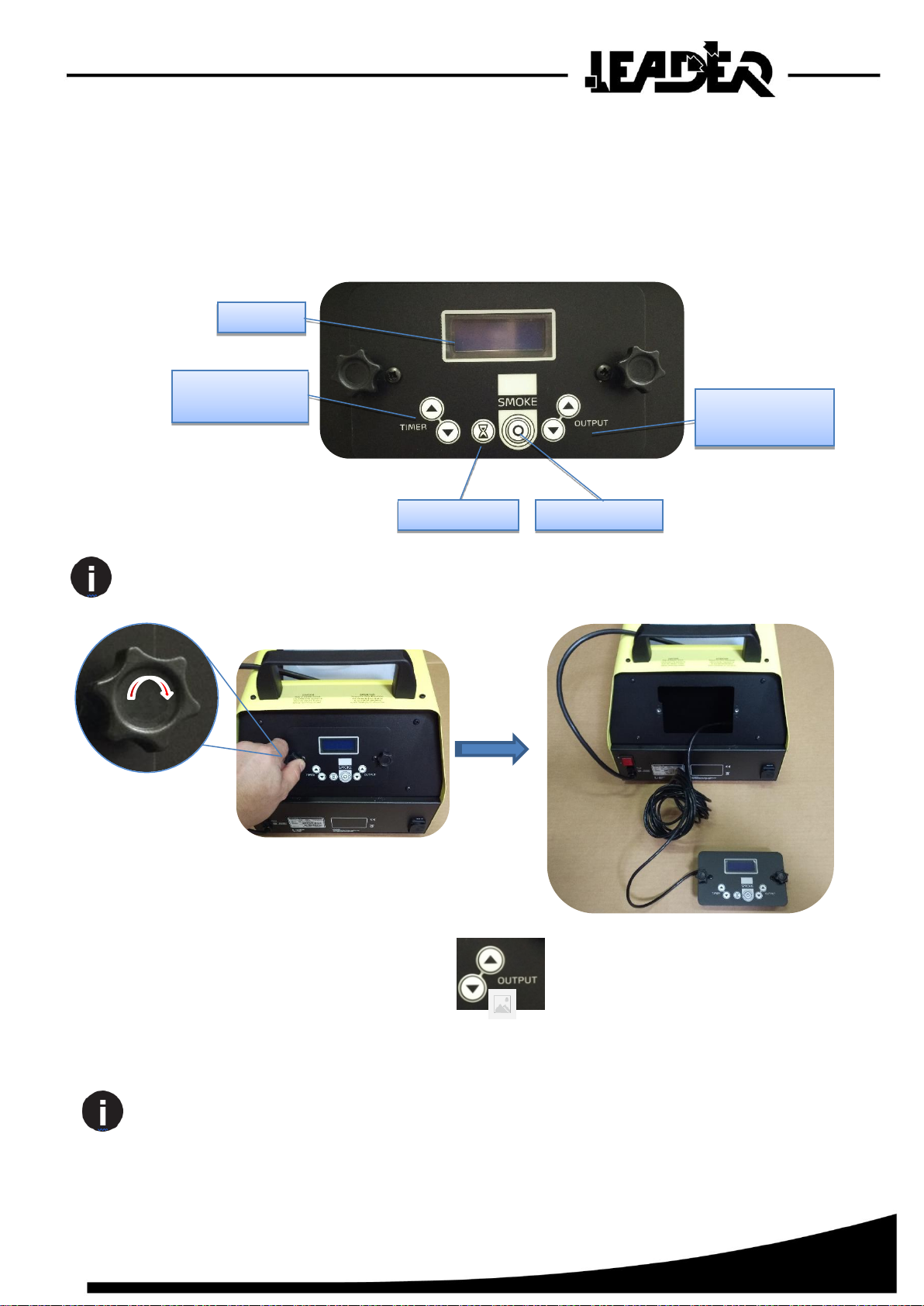
8.1 Overview
The integrated digital remote control on the rear of the machine allows you to configure it
using option menus.
The integrated digital remote control may be removed from the unit and used as a handheld
remote control by removing the two hand wheel bolts either side of the display.
8.2 Setting smoke output level
Use the output “UP” / “DOWN” buttons to select the desired output
performance. Once the value is selected it is automatically stored.
The machine will automatically default to standby at power up as opposed to resuming any
previous operational state.
Smoke Button
Display
Timer value
Up/Down buttons
Timer button
Output level
Up/Down buttons

15
8.3 Setting continuous operation
At power up the machine will automatically heat to its operating temperature.
When the operating temperature is reached the display will show “READY”.
To set continuous operation, adjust output level to desired value and press “SMOKE”
button.
Whilst the unit is producing smoke the screen will display “Continuous xx%”
to indicate its mode and output level.
The unit will continuously produce smoke until the “SMOKE” button is pressed
again or the fluid supply is exhausted (whichever is sooner).
8.4 Setting the Timer
Use the timer button to toggle between “runtime”
and “offtime”.
To enable the run timer function, set a non-zero value to the runtime using the timer
UP/DOWN buttons.
When runtime is zero the runtime is shown as “OFF” , indicating the
timers will not run.
To Select the off timer value, set a non-zero value to the offtime.
To engage the timer press the “SMOKE” button with a programmed runtime
value.
Whilst the unit is producing smoke the screen will display “Timer xx%”
to indicate its mode and output level.
The machine will begin a cycle of producing fog for the programmed runtime and stopping
production for the programmed offtime until the “SMOKE”
button is pressed again of the fluid supply is depleted (whichever is sooner).
READY 00%
CONTINUOUS 00%
FOG LEVEL 00%
RUN TIME 03
RUN TIME 00
RUN TIME
OFF
16
8.5 Resetting the machine after fluid out
If the machine runs out of fluid, it will automatically shut down and show FLUID OUT
on the display to prevent damage to the pump(s).
To reset this, fault down power the system and refill the fluid reservoir.
Avoid prolonged operation without fluid, since this will damage the pump and prevent
the machine from re-priming.
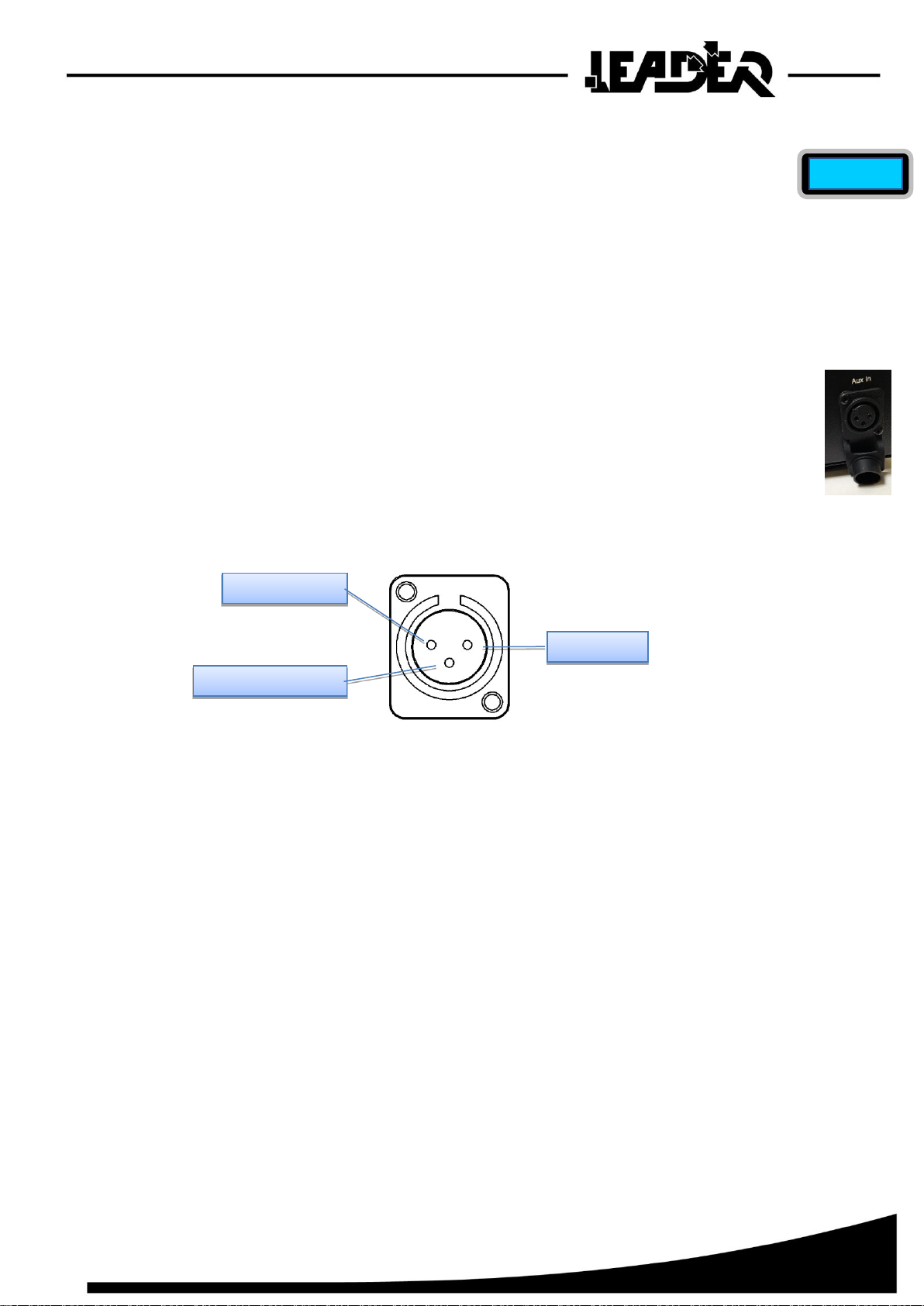
8.6 Auxiliary input
AN auxiliary input is provided for applications requiring an additional means of triggering
the machine other than the remote control.
The rear mounted XLR socket provides 12V DC at 50mA to power an interface device.
This can be used to trigger the machine using a clean contact closure.
The interface may also be used with a common 0-10V signal.
The input signal at pin 3 will trigger the machine operation when it is taken above 2V.
The operating level and mode (continuous or timer) will be taken from the current settings
on the remote, as will the output level.
FLUID OUT
Pin 1 ground
Pin 2 12V
Pin 3 0-10V input

17
9APPROVED FOG FLUID TYPES
The LEADER Smoke machines must only be used with the LEADER
fluids listed below. LEADER supplies high quality fog fluids
that are based on ultra-pure deionized water. No other fluid is suitable
for use.
Trainer Fluid (Medium)
This fluid is used in areas where shorter duration training exercises
occur and faster dispersal of the fog is required.
Trainer fluid (Heavy)
This fluid is used when maximum persistence is required or a very
heavy
density of fog is required to simulate a complete “white out”.
DANGER! The LEADER Smoke range machines can run safely only on the specific
fog fluids they are designed for. Use ONLY the LEADER fog fluids designated in this
manual. NEVER use any other type of fluid, or toxic gas may be produced. You will
probably also cause damage to the machine that will invalidate the product warranty.
Do not dilute fog fluid with water or any other liquid. Discard fog fluid if it becomes
contaminated.

18
10 BASIC SERVICE
Before servicing the Trainer machines, read and observe all the precautions listed in
“Safety information” on page 4. Any service not described in this section must be
carried out by a LEADER technician.
10.1 Cleaning
Excessive dust, fog fluid, and dirt build-up will degrade performance and cause overheating
and damage to the machine that is not covered by the product warranty. To maintain
adequate cooling, dust must be cleaned from the outer casing and air vents of the machine
periodically.
Isolate the machine from power and allow to cool completely before cleaning. The fog
output nozzles remain hot for a period after use.
•Remove dust from the air vents with a soft brush, cotton swab, vacuum, or compressed
air.
•Clean fog fluid residues from the fog output of the machine using a damp cloth.
•Clean the outer casing with a damp cloth only.
10.2 Fuse replacement
The main fuse for the machine is located adjacent to the power inlet on the rear panel.
There is also a T3.15 A fuse located on the electronics board inside the unit which
protects the supply to the pump.
DANGER! Disconnect the power supply before removing any covers orchanging fuses.
Live parts inside!
Rear panel fuse
LEADER Smoke 3: 6.3 AT (slow-blow), 250 V
10 AT (slow-blow), 110 V
LEADER Smoke 5: 12.5 AT (slow-blow), 250 V
20 AT (slow-blow), 110 V
Replace fuse only with one of exactly the same size and rating. Contact LEADER
if the fuse blows repeatedly.
To replace the internal fuse, disconnect the power cord from the supply, unscrew
the screws holding the top cover of the unit and remove the cover. The electronics
board is located in the side compartment.

19
11 TROUBLESHOOTING
12 Status messages
Problem
Probable cause(s)
Suggested remedy
Machine will not produce fog
when control panel set to
CONTINUOUS or fog button
pressed
Machine not at operating temperature
Wait until HEAT message no longer
shown
FOG option set to 0
Increase setting
Fog output is weak
Machine requires priming
Down power the unit, ensure the fluid
bottle is full and the tube is fully
inserted.
Wet, greasy, non-uniform fog
output, fluid drips or spits from
nozzle, or very loud noise when
firing machine
Incompatible fog flui
Use approved fluid!
Machine appears dead
Mains fuse blown
Replace fuse (page 17)
No power at AC cable inlet
Check power cable and circuit breaker
Loss of control from remote
Communication issue between remote and
machine
Check cable connection between
remote and machine
Message
Reason
HEAT
The unit is heating up to operating temperature.
READY
The heater is at operating temperature, but Fog is not turned on (RUN set to STANDBY).
FLUID OUT
Run out of fluid. Refill the fluid tank and then down power the machine to reset the fault.
CALIBRATION ERROR
The machine has detected an error with its calibration settings and will not operate.
Call LEADER for assistance.
SYSTEM ERROR
The machine has detected an error in the temperature sensor and will not
operate. Call LEADER for assistance.
COMM ERROR
Remote has lost communication with the machine and will not operate. Call LEADER for
assistance.

20
Notes
This manual suits for next models
5
Table of contents
Other Tempest Fog Machine manuals


