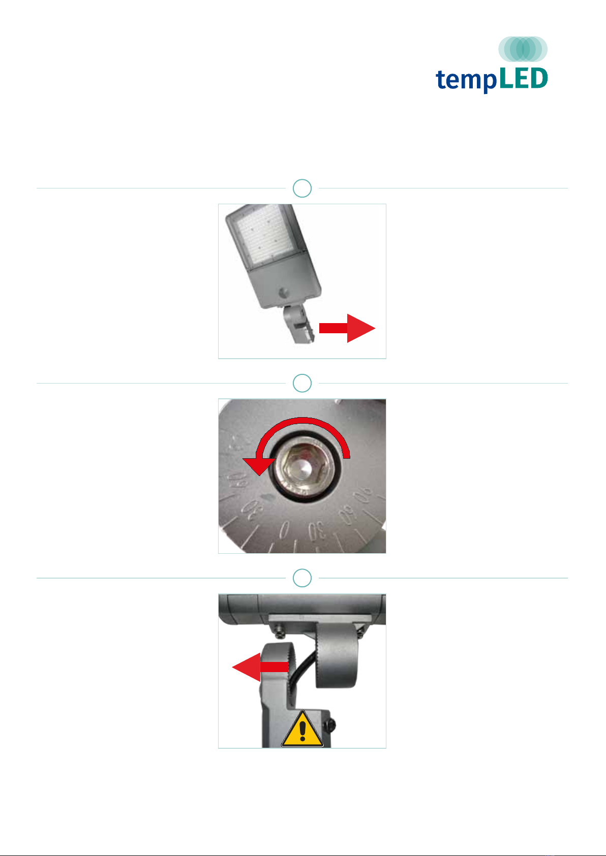
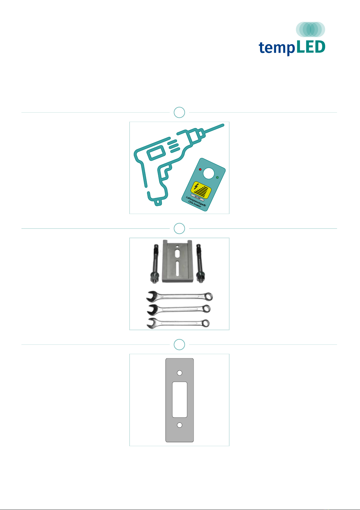
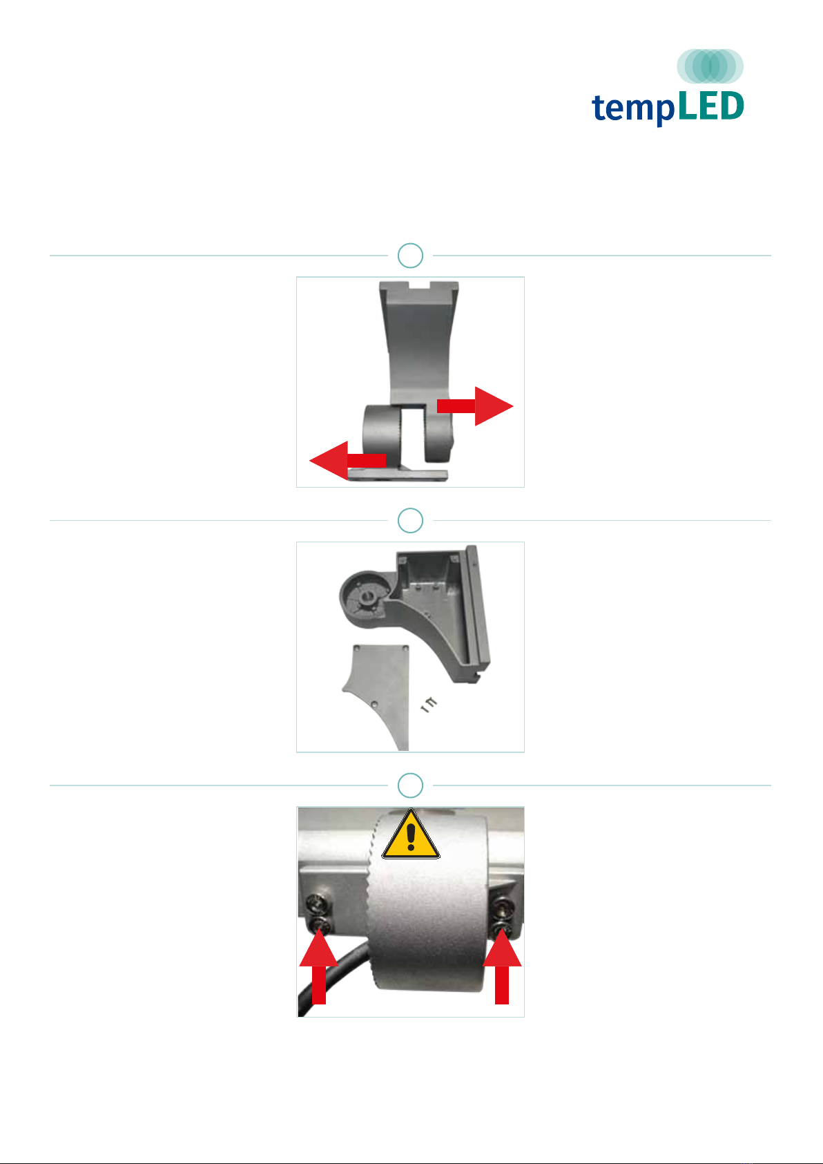
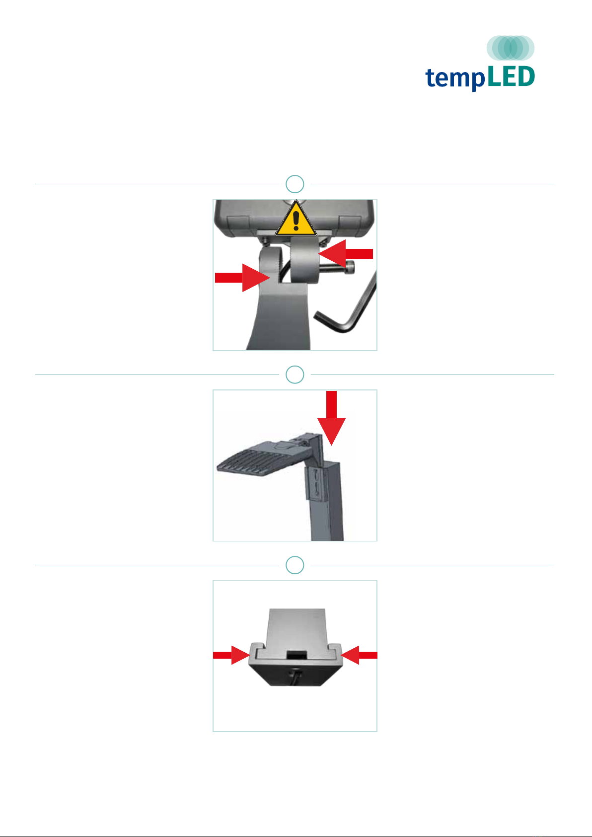
tempLED RayTrack Series User manual

MONTAGEANLEITUNG
INSTALLATION GUIDE
tempLED RayTrack
tempLED GmbH
V.01/2019
Modulares Premium LED-Aussenleuchtensystem
Modular & premium-class LED outdoor lighting system

© tempLED GmbH |Marmorwerkstraße 52 |83088 Kiefersfelden |Deutschland
MONTAGEANLEITUNG
tempLED RayTrack Serie
Allgemeine Sicherheitshinweise
INSTALLATION GUIDE
tempLED RayTrack series
General safety notes
Vorsicht!
Gefahr eines elektrischen Schlages!
Montage und Inbetriebnahme der Leuchte nur
durch autorisierte Fachkräfte. Vor jeder Arbeit
an der Leuchte die Stromzufuhr unterbrechen
und gegen versehentliches Wiedereinschalten
sichern. Die Leuchte darf nur mit vollständigem
und unbeschädigtem Gehäuse in Betrieb genom-
men werden. Die Stromzufuhr ist mit geeigneten
Maßnahmen (Fehlerstrom-Schutzschalter o.ä.)
abzusichern.
Caution!
Risk of electric shock!
Mounting and installation of the luminaire only by
authorized personnel. Disconnect the power sup-
ply and protect it from restart by mistake before
working on the luminaire. The luminaire must
only be operated with complete and undam-
aged housing. Please secure the main power
by means of suitable measures, for example a
residual current circuit breaker.
1
Vorsicht!
Absturzgefahr!
Bei der Montage der Leuchte ist darauf zu
achten, dass das gewählte Montagematerial
(Schrauben, Dübel) sowie die Dimensionen von
Bohrlöchern und Schrauben für das Gewicht der
Leuchte und die Beschaffenheit und Tragfähig-
keit der Montageoberäche geeignet ist.
Keine Haftung für fehlerhaft ausgeführte Monta-
ge, unsachgemäßen Betrieb oder Veränderun-
gen an der Leuchte!
Caution!
Danger of falling!
Please use suitable mounting material (screws,
wall plugs) and dimensions for the drilling holes
and screws. They must be suitable for the weight
of the luminaire as well as the composition and
bearing capacity of the mounting location. No
liability for damages resulting from improper
installation, inexpert operation or modication of
the luminaire!
2
Lieferumfang:
- Leuchte der RayTrack-Serie mit
vormontiertem Mastaufsatz
Package contents:
- RayTrack luminaire with
preassembled pole top holder
3
V.01/2019

© tempLED GmbH |Marmorwerkstraße 52 |83088 Kiefersfelden |Deutschland
MONTAGEANLEITUNG
tempLED RayTrack Serie
Mastaufsatzmontage
INSTALLATION GUIDE
tempLED RayTrack series
Pole top mounting
Schritt 1:
Schrauben lösen
Lösen Sie zuerst die vier Halteschrau-
ben am Mastaufsatz mit Hilfe eines
Ringschlüssels der Größe 13 mm.
Step 1:
Loosen screws
Loosen the four holder screws at the
pole top holder by using a ring spanner
size 13.
1
Schritt 2:
Netzanschlusskabel einführen
Verbinden Sie das Netzkabel der
tempLED RayTrack und fädeln es in
den Masten ein.
Details zur Adernbelegung nden Sie
im Kapitel „elektrischer Netzanschluss“
in dieser Montageanleitung.
Step 2:
Feed in the power supply cable
Connect the power supply cable of the
tempLED RayTrack and feed the power
cable into the pole.
You nd detailed information for the
wiring in the chapter “electrical power
input” in this installation guide.
U
2
Schritt 3:
RayTrack aufsetzen
Setzen Sie die Leuchte auf den Mast
auf.
Achtung! Quetschgefahr für das Netz-
kabel!
Step 3:
Setting the RayTrack luminaire
Set on the luminaire onto the pole.
Caution! The power cable might be-
come damaged!
3
V.01/2019

© tempLED GmbH |Marmorwerkstraße 52 |83088 Kiefersfelden |Deutschland
MONTAGEANLEITUNG
tempLED RayTrack Serie
Mastaufsatzmontage
INSTALLATION GUIDE
tempLED RayTrack series
Pole top mounting
Schritt 4:
Schrauben festdrehen
Ziehen Sie die vier Halteschrauben am
Mastaufsatz mit Hilfe eines Ringschlüs-
sels der Größe 13 mm fest.
Step 4:
Tighten screws
Tighten the four holder screws at the
pole top holder by using a ring spanner
size 13.
4
Schritt 5:
Neigungswinkel einstellen
Stellen Sie zum Schluss den ge-
wünschten Neigungswinkel der
tempLED RayTrack mit Hilfe der
Winkelskala an der Neigungsverstel-
lung ein.
Step 5:
Set the tilt angle
Select the required tilt angle of the
tempLED RayTrack with the help of the
angle scale of the tilt adjustment.
5
Schritt 6:
Neigungsverstellung xieren
Ziehen Sie die Halteschraube der
Neigungsverstellung mit Hilfe eines
Inbusschlüssels der Größe 14 mm fest.
Step 6:
Fixing the tilt adjustment
Tighten the holder screw of the tilt ad-
justment by using an Allen key size 14
or a hex wrench size 14.
6
V.01/2019

© tempLED GmbH |Marmorwerkstraße 52 |83088 Kiefersfelden |Deutschland
MONTAGEANLEITUNG
tempLED RayTrack Serie
Bügelmontage
INSTALLATION GUIDE
tempLED RayTrack series
Surface mounting
Schritt 1:
Entfernen des Mastaufsatzes 1
Bitte entfernen Sie zuerst den vormon-
tierten Mastaufsatz von der Leuchte.
Step 1:
Remove the pole top holder 1
First, please remove the preassembled
pole top holder from the luminaire.
1
Schritt 2:
Entfernen des Mastaufsatzes 2
Lösen Sie die Halteschraube der Nei-
gungsverstellung des Mastaufsatzes
mit einem Inbusschlüssel der Größe
14 mm und ziehen Sie die Schraube
heraus.
Step 2:
Remove the pole top holder 2
Loosen the holder screw of the tilt ad-
justment of the pole top holder with an
Allen key size 14 or a hex wrench size
14 and remove the screw.
2
Schritt 3:
Entfernen des Mastaufsatzes 3
Ziehen Sie die beiden Bauteile des
Mastaufsatzes auseinander und fädeln
Sie das Netzkabel vorsichtig aus.
Step 3:
Remove the pole top holder 3
Pull the two parts of the pole top holder
apart and unthread the power cable
carefully.
3
V.01/2019

© tempLED GmbH |Marmorwerkstraße 52 |83088 Kiefersfelden |Deutschland
MONTAGEANLEITUNG
tempLED RayTrack Serie
Bügelmontage
INSTALLATION GUIDE
tempLED RayTrack series
Surface mounting
Schritt 4:
Entfernen des Mastaufsatzes 4
Öffnen Sie die vier Halteschrauben des
Mastaufsatzes mit Hilfe eines Inbus-
schlüssels der Größe 6.
Fädeln Sie anschließend das Netzka-
bel vorsichtig aus.
Nehmen Sie zum Schluß den Mastauf-
satz komplett ab.
Step 4:
Remove the pole top holder 4
Loosen the four screws of the pole top
holder with an Allen key size 6 or a hex
wrench size 6.
Unthread the power cable carefully
afterwards.
At last, remove the pole top holder
completely.
4
Schritt 5:
Anzeichnen der Bohrlöcher
Zeichnen Sie die Bohrlöcher an der
Oberäche des Montageortes an.
Nehmen Sie dazu die nebenstehende
Masszeichnung zur Hilfe:
Step 5:
Marking the drill holes
Mark the drill holes on the surface of
the mounting location. Please use the
measurement drawing on the left:
32,50 mm 20,00 mm 32,50 mm
75,00 mm 75,00 mm
150,00 mm
50,00 mm
12,50 mm
RayTrack 40 / 75 / 115 / 145: 280,00 mm
RayTrack 180 / 200 / 230: 365,00 mm
RayTrack 300 / 420: 380,00 mm
5
Schritt 6:
Bohrlöcher anfertigen
Prüfen Sie ggf. die Stellen der Bohrlö-
cher mit einem Leitungssuchgerät und
fertigen Sie dann die Bohrlöcher an.
Wählen Sie einen der Montageober-
äche und dem Gewicht der Leuchte
angepassten Bohrlochdurchmesser.
(Symbolabbildung)
Step 6:
Drilling the holes
Please check the drilling spots with a
line locator and drill the holes. Choose
a drill hole diameter suitable for the
material of the mounting surface and
the weight of the luminaire.
(symbol illustration)
Leitungssuchgerät
Line locator
ON / OFF
6
V.01/2019
Driller icon made by Freepik from www.aticon.com

© tempLED GmbH |Marmorwerkstraße 52 |83088 Kiefersfelden |Deutschland
MONTAGEANLEITUNG
tempLED RayTrack Serie
Bügelmontage
INSTALLATION GUIDE
tempLED RayTrack series
Surface mounting
Schritt 7:
Montieren des Montagebügels
Montieren Sie den Montagebügel mit
geeignetem Schraubenmaterial für die
Montageoberäche und dem Gewicht
der Leuchte. Wir empfehlen den Ein-
satz von Edelstahlschrauben.
(Symbolabbildung)
Step 7:
Mounting the holder
Screw the holder to the surface. Use
screw material suitable for the mount-
ing surface and the weight of the lumin-
aire. We recommend high-grade steel
screws and mounting material.
(symbol illustration)
7
Schritt 8:
Leuchte in Montagebügel einsetzen
Setzen Sie die tempLED RayTrack in
den Montagebügel ein. Stellen Sie den
gewünschten Neigungswinkel ein und
ziehen die beiden Halteschrauben mit
Beilagscheiben und Abstandshalter des
Montagebügels mit Hilfe eines Ring-
schlüssels der Größe 13 mm fest.
Step 8:
Insert luminaire into the holder
Insert the tempLED RayTrack into the
holder. Select the required tilt angle
and tighten the two holder screws with
the two washers and the two spacers
by using a ring spanner size 13.
8
V.01/2019

© tempLED GmbH |Marmorwerkstraße 52 |83088 Kiefersfelden |Deutschland
MONTAGEANLEITUNG
tempLED RayTrack Serie
Montage mit Wandhalter
INSTALLATION GUIDE
tempLED RayTrack series
Wall mounting
Schritt 1:
Entfernen des Mastaufsatzes 1
Bitte entfernen Sie zuerst den vormon-
tierten Mastaufsatz von der Leuchte.
Step 1:
Remove the pole top holder 1
First, please remove the preassembled
pole top holder from the luminaire.
1
Schritt 2:
Entfernen des Mastaufsatzes 2
Lösen Sie die Halteschraube der Nei-
gungsverstellung des Mastaufsatzes
mit einem Inbusschlüssel der Größe
14 mm und ziehen Sie die Schraube
heraus.
Step 2:
Remove the pole top holder 2
Loosen the holder screw of the tilt ad-
justment of the pole top holder by using
an Allen key size 14 or a hex wrench
size 14 and remove the screw.
2
Schritt 3:
Entfernen des Mastaufsatzes 3
Ziehen Sie die beiden Bauteile des
Mastaufsatzes auseinander und fädeln
Sie das Netzkabel vorsichtig aus.
Step 3:
Remove the pole top holder 3
Pull the two parts of the pole top holder
apart and unthread the power cable
carefully.
3
V.01/2019

© tempLED GmbH |Marmorwerkstraße 52 |83088 Kiefersfelden |Deutschland
MONTAGEANLEITUNG
tempLED RayTrack Serie
Montage mit Wandhalter
INSTALLATION GUIDE
tempLED RayTrack series
Wall mounting
Schritt 4:
Entfernen des Mastaufsatzes 4
Öffnen Sie die vier Halteschrauben des
Mastaufsatzes mit Hilfe eines Inbus-
schlüssels der Größe 6.
Fädeln Sie anschließend das Netzka-
bel vorsichtig aus.
Nehmen Sie zum Schluß den Mastauf-
satz komplett ab.
Step 4:
Remove the pole top holder 4
Loosen the four screws of the pole top
holder with an Allen key size 6 or a hex
wrench size 6.
Unthread the power cable carefully
afterwards.
At last, remove the pole top holder
completely.
4
Schritt 5:
Halteplatte entfernen
Ziehen Sie die Halteplatte vom Wand-
halter ab.
Step 5:
Remove the retaining plate
Remove the retaining plate from the
wall mount.
5
Schritt 6:
Anzeichnen der Bohrlöcher
Zeichnen Sie die Bohrlöcher an der
Oberäche des Montageortes an.
Nehmen Sie dazu die nebenstehende
Masszeichnung zur Hilfe.
Achten Sie darauf, dass das Zulei-
tungskabel durch eine der Öffnungen in
der Halteplatte passt.
Step 6:
Marking the drill holes
Mark the drill holes on the surface of
the mounting location. Please use the
measurement drawing on the left.
Make sure that the power cable can be
threaded through one of the holes of
the retaining plate.
12,00 mm
18,00 mm
52,50 mm 52,50 mm
105,00 mm
155,00 mm
Ø 10,00 mm
38,00 mm60,00 mm
6
V.01/2019

© tempLED GmbH |Marmorwerkstraße 52 |83088 Kiefersfelden |Deutschland
MONTAGEANLEITUNG
tempLED RayTrack Serie
Montage mit Wandhalter
INSTALLATION GUIDE
tempLED RayTrack series
Wall mounting
Schritt 7:
Bohrlöcher anfertigen
Prüfen Sie ggf. die Stellen der Bohrlö-
cher mit einem Leitungssuchgerät und
fertigen Sie dann die Bohrlöcher an.
Wählen Sie einen der Montageober-
äche und dem Gewicht der Leuchte
angepassten Bohrlochdurchmesser.
(Symbolabbildung)
Step 7:
Drilling the holes
Please check the drilling spots with a
line locator and drill the holes. Choose
a drill hole diameter suitable for the
material of the mounting surface and
the weight of the luminaire.
(symbol illustration)
Leitungssuchgerät
Line locator
ON / OFF
7
Schritt 8:
Montieren der Halteplatte
Montieren Sie die Halteplatte des
RayTrack-Wandhalters mit geeignetem
Schraubenmaterial für die Montageob-
eräche und dem Gewicht der Leuchte.
Wir empfehlen den Einsatz von Edel-
stahlschrauben.
(Symbolabbildung)
Step 8:
Mounting the retaining plate
Screw the retaining plate of the wall
holder to the surface. Use screw ma-
terial suitable for the mounting surface
and the weight of the luminaire. We
recommend high-grade steel screws
and mounting material.
(symbol illustration)
8
Schritt 9:
Verwendung der Rückenplatte
Bei der Montage des RayTrack-Wand-
halters an dünnwandigen Monta-
georten (Metallverkleidungen, Masten
usw.) empfehlen wir aus Gründen der
Stabilität die Verwendung der mitgelie-
ferten Rückenplatte.
Step 9:
Using the backplate
If you mount the RayTrack wall mount
on thin-walled mounting places (e.g.
metal cladding, thin poles) we recom-
mend using the included backplate for
stability reasons.
9
V.01/2019
Driller icon made by Freepik from www.aticon.com

© tempLED GmbH |Marmorwerkstraße 52 |83088 Kiefersfelden |Deutschland
MONTAGEANLEITUNG
tempLED RayTrack Serie
Montage mit Wandhalter
INSTALLATION GUIDE
tempLED RayTrack series
Wall mounting
Schritt 10:
Rückenplatte einsetzen
Setzen Sie die Rückenplatte am Mon-
tageort auf der Rückseite des dünn-
wandigen Materials an.
(Symbolabbildung am Beispiel eines
Mastens)
Step 10:
Set in backplate
At the mounting location, place the
backplate on the backside of the thin-
walled material.
(symbol illustration with the example of
a pole)
10
Schritt 11:
Rückenplatte verschrauben
Verschrauben Sie die Rückenplatte mit
der Halteplatte des RayTrack-Wandhal-
ters mit geeignetem Schraubenmaterial
für die Montageoberäche und dem
Gewicht der Leuchte. Wir empfehlen
den Einsatz von Edelstahlschrauben.
(Symbolabbildung am Beispiel eines
Mastens)
Step 11:
Mounting the back plate
Screw the backplate and the retaining
plate of the wall holder together. Use
screw material suitable for the mount-
ing surface and the weight of the lumin-
aire. We recommend high-grade steel
screws and mounting material.
(symbol illustration with the example of
a pole)
11
Schritt 12:
Vorbereiten des Wandhalters 1
Lösen Sie die Halteschraube der Nei-
gungsverstellung des Wandhalters mit
Hilfe eines Inbusschlüssels der Größe
14 mm.
Step 12:
Preparing the wall mount 1
Loosen the holding screw of the tilt ad-
justment of the wall mount with an Allen
Key size 14 or an hex wrench size 14.
12
V.01/2019

© tempLED GmbH |Marmorwerkstraße 52 |83088 Kiefersfelden |Deutschland
MONTAGEANLEITUNG
tempLED RayTrack Serie
Montage mit Wandhalter
INSTALLATION GUIDE
tempLED RayTrack series
Wall mounting
Schritt 13:
Vorbereiten des Wandhalters 2
Ziehen Sie anschließend die beiden
Teile der Neigungsverstellung des
Wandhalters auseinander.
Step 13:
Preparing the wall mount 2
Pull the two parts of the tilt adjustment
of the wall mount apart.
13
Schritt 14:
Vorbereiten des Wandhalters 3
Öffnen Sie die drei Kreuzschrauben
des Verkabelungsraums an der Seite
des Wandhalters und nehmen Sie den
Deckel ab.
Step 14:
Preparing the wall mount 3
Loosen the three Phillips screws of
the cable space on the side of the wall
mount and remove the top cover.
14
Schritt 15:
Anbau des Wandhalters 1
Fädeln Sie das Netzkabel vorsichtig
in den kleinen Teil der Neigungsver-
stellung der Wandhalterung ein und
schrauben ihn anschließend mit den
vier Schrauben und einem Inbusschlüs-
sel der Größe 6 mm am Leuchtenge-
häuse fest.
Achtung! Quetschgefahr für das Netz-
kabel!
Step 15:
Attachment of the wall mount 1
Thread the power cable carefully into
the smaller part of the tilt adjustment
of the wall mount and tighten it to the
luminaire housing with the four screws
by using an Allen key size 6 or a hex
wrench size 6.
Caution! The power cable might be-
come damaged!
15
V.01/2019

© tempLED GmbH |Marmorwerkstraße 52 |83088 Kiefersfelden |Deutschland
MONTAGEANLEITUNG
tempLED RayTrack Serie
Montage mit Wandhalter
INSTALLATION GUIDE
tempLED RayTrack series
Wall mounting
Schritt 16:
Anbau des Wandhalters 2
Fädeln Sie das Netzkabel vorsichtig
in den größeren Teil der Neigungsver-
stellung der Wandhalterung ein und
schrauben diese mit der Halteschraube
und einem Inbusschlüssel Größe 14
mm vorläug fest.
Achtung! Quetschgefahr für das Netz-
kabel!
Step 16:
Attachment of the wall mount 2
Thread the power cable carefully into
the bigger part of the tilt adjustment of
the wall mount and tighten it provision-
ally with the holder screw by using an
Allen key size 14 or a hex wrench size
14.
Caution! The power cable might be-
come damaged!
16
Schritt 17:
Einsetzen des Wandhalters
Setzen Sie den Wandhalter von oben
in die bereits an der Wand montierte
Halteplatte ein.
Step 17:
Placing the wall mount
Insert the wall mount from above into
the already installed retaining plate.
17
Schritt 18:
Fixieren des Wandhalter
Schrauben Sie den Wandhalter mit
Hilfe der beiden Schrauben links und
rechts mit Hilfe eines Inbusschlüssels
der Größe 3 mm an der Halteplatte
fest.
Step 18:
Fixing the wall mount
Fix the wall mount to the retaining plate
with the two screws on the left and on
the right by using an Allen key size 3 or
a hex wrench size 3.
18
V.01/2019

© tempLED GmbH |Marmorwerkstraße 52 |83088 Kiefersfelden |Deutschland
MONTAGEANLEITUNG
tempLED RayTrack Serie
Montage mit Wandhalter
INSTALLATION GUIDE
tempLED RayTrack series
Wall mounting
Schritt 19:
Netzanschluss herstellen
Stellen Sie im Verkabelungsraum des
Wandhalters den Netzanschluss her.
Details zur Adernbelegung nden Sie
im Kapitel „elektrischer Netzanschluss“
in dieser Montageanleitung.
Step 19:
Connect the power cable
Connect the power cable inside the
cable space of the wall mount.
You nd detailed information for the
wiring in the chapter “electrical power
input” in this installation guide.
19
Schritt 20:
Schließen des Verkabelungsraums
Setzen Sie anschließend den Deckel
auf den Verkabelungsraum auf und
ziehen die drei Kreuzschrauben fest.
Step 20:
Closing the cable space
Place the top cover on the cable space
and tighten the three Phillips screws.
20
Schritt 21:
Fixieren der Neigungsverstellung
Stellen Sie zum Schluss den ge-
wünschten Neigungswinkel der tem-
pLED RayTrack mit Hilfe der Winkels-
kala an der Neigungsverstellung ein
und ziehen die Halteschraube mit Hilfe
eines Inbusschlüssels der Größe 14
mm endgültig fest.
Step 21:
Fixing the tilt adjustment
Select the required tilt angle of the
tempLED RayTrack with the help of the
angle scale of the tilt adjustment and
tighten the holder screw by using an
Allen key size 14 or a hex wrench size
14.
21
V.01/2019

© tempLED GmbH |Marmorwerkstraße 52 |83088 Kiefersfelden |Deutschland
MONTAGEANLEITUNG
tempLED RayTrack Serie
Elektrischer Netzanschluss
INSTALLATION GUIDE
tempLED RayTrack series
Electrical power input
Schritt 1: Vorsicht!
Gefahr eines elektrischen Schlages!
Montage und Inbetriebnahme der Leuchte nur
durch autorisierte Fachkräfte. Vor jeder Arbeit
an der Leuchte die Stromzufuhr unterbrechen
und gegen versehentliches Wiedereinschalten
sichern.
Step 1: Caution!
Risk of electric shock!
Mounting and installation of the luminaire only by
authorized personnel. Disconnect the power sup-
ply and protect it from restart by mistake before
working on the luminaire.
1
Schritt 2:
Adernbelegung
Die Adernbelegung des Netzkabels
lautet wie folgt:
Phase [L] - braun
Schutzleiter (Erdung) - gelb/grün
Neutralleiter [N] - blau
Step 2:
Wiring
The wiring of the power cable is as
follows:
Power conductor [L] - brown
Protective conductor - yellow/green
Neutral conductor [N] - blue
L
N
2
Schritt 3:
Netzanschluss direkt in der Leuchte
Alternativ können Sie den Netzan-
schluss auch direkt in der Leuchte
herstellen. Den passenden Verkabe-
lungsplan nden Sie auf der nächsten
Seite. Der maximal verwendbare
Kabeltyp ist 3x 1,00 mm². Optional ist
eine Sonderkabelverschraubung für die
Kabeltypen 5x 1,50 mm² oder 3x 2,50
mm² erhältlich.
Step 3:
Direct power cabeling
Alternatively, you can connect the
power cable directly to the luminaire.
Please nd the wiring diagram on the
next page. The maximum usable cable
type is 3 x 1.00 mm². A special cable
screw for the cable types 5 x 1.50 mm²
oder 3 x 2.50 mm² is available as addi-
tional accessory.
3
V.01/2019

© tempLED GmbH |Marmorwerkstraße 52 |83088 Kiefersfelden |Deutschland
MONTAGEANLEITUNG
tempLED RayTrack Serie
Verkabelungsdiagramm
INSTALLATION GUIDE
tempLED RayTrack series
Wiring diagram
V.01/2019
Netzzuleitung
electrical power input
Überspannungsschutz
over voltage protection
LED-Netzteil
LED power supply
Erdung Leuchtengehäuse
grounding luminaire housing
LED-Lichtfeld
LED light field
L N
X
N/A
CONTROL*
* nur zum Anschluss des RayTrack Multisensors!
* for connection with the RayTrack multi sensor only!

© tempLED GmbH |Marmorwerkstraße 52 |83088 Kiefersfelden |Deutschland
MONTAGEANLEITUNG
tempLED RayTrack Serie
Ausrichten der Optik
INSTALLATION GUIDE
tempLED RayTrack series
Optics alignment
Schritt 1: Vorsicht!
Gefahr eines elektrischen Schlages!
Ausrichten der Optik nur durch autorisierte
Fachkräfte. Vor jeder Arbeit an der Leuchte die
Stromzufuhr unterbrechen und gegen versehent-
liches Wiedereinschalten sichern.
ACHTUNG!
Legen Sie ausgebaute Optiken nur auf weiche
Oberächen und üben Sie keinen Druck aus!
Step 1: Caution!
Risk of electric shock!
Aligning the optics only by authorized person-
nel. Disconnect the power supply and protect it
from restarting by mistake before working on the
luminaire.
CAUTION!
Please place the optics removed only on a soft
surface and do not any exert pressure!
1
Schritt 2:
Ausrichtung der Optik erkennen 1
So erkennen Sie die Ausrichtung
der Lichtlenkungsoptik der tempLED
RayTrack auf dem Bild rechts:
Abstrahlwinkel nach vorne [1]: 75°
Abstrahlwinkel nach links [2]: 75°
Abstrahlwinkel nach hinten [3]: 5°
Abstrahlwinkel nach rechts [4]: 75°
Bild zeigt den Auslieferungszustand!
Step 2:
Recognizing optics alignment 1
Identifying the optics alignment of the
tempLED RayTrack luminaire on the
picture to the left:
Beam angle to the front [1]: 75°
Beam angle to the left [2]: 75°
Beam angle to the back [3]: 5°
Beam angle to the right [4]: 75°
Picture shows factory state!
2
Schritt 3:
Ausrichtung der Optik erkennen 2
So erkennen Sie die Ausrichtung
der Lichtlenkungsoptik der tempLED
RayTrack im Detail auf dem Bild rechts:
Abstrahlwinkel nach vorne [1]: 75°
Abstrahlwinkel nach links [2]: 75°
Abstrahlwinkel nach hinten [3]: 5°
Abstrahlwinkel nach rechts [4]: 75°
Bild zeigt den Auslieferungszustand!
Step 3:
Recognizing optics alignment 2
Identifying the optics alignment of the
tempLED RayTrack luminaire in detail
on the picture to the left:
Beam angle to the front [1]: 75°
Beam angle to the left [2]: 75°
Beam angle to the back [3]: 5°
Beam angle to the right [4]: 75°
Picture shows factory state!
3
V.01/2019
1
3
1
3
4
42
2

© tempLED GmbH |Marmorwerkstraße 52 |83088 Kiefersfelden |Deutschland
MONTAGEANLEITUNG
tempLED RayTrack Serie
Ausrichten der Optik
INSTALLATION GUIDE
tempLED RayTrack series
Optics alignment
Schritt 4:
Schrauben lösen
Lösen Sie die Schrauben der Optik
und legen diese sorgfältig beiseite. Die
Optik besitzt vier Kreuzschrauben [1]
und 16 Inbusschrauben der Größe 2,5
mm [2].
Step 13:
Loosen screws
Loosen the screws of the optics and
put them aside carefully. The optics
has four Phillips screws [1] and 16 hex
screws size 2.5 mm [2].
4
Schritt 5:
Achtung! Dichtungen!
Die Optik besitzt eine rundumlaufende
Dichtung [1].
Die vier Kreuzschrauben besitzen
ebenfalls je einen Dichtungsring [2].
Achten Sie darauf, keine Dichtungen
zu verlieren!
Step 5:
Caution! Seals!
The optics has one circuit seal [1].
Each of the four Phillips screws also
has a seal ring [2].
Be careful not to lose any of the seal-
ings!
5
Schritt 6:
Ausrichtung der Optik auf 0°
Dies ist der Auslieferungszustand.
Der Abstrahlwinkel der tempLED
RayTrack hat dann folgende Werte:
Abstrahlwinkel nach vorne [1]: 75°
Abstrahlwinkel nach links [2]: 75°
Abstrahlwinkel nach hinten [3]: 5°
Abstrahlwinkel nach rechts [4]: 75°
Step 6:
Optics alignment at 0°
This is the factory state.
The beam angle of the tempLED
RayTrack is then as followes:
Beam angle to the front [1]: 75°
Beam angle to the left [2]: 75°
Beam angle to the back [3]: 5°
Beam angle to the right [4]: 75°
6
V.01/2019
1
1
2
2
1
3
42

© tempLED GmbH |Marmorwerkstraße 52 |83088 Kiefersfelden |Deutschland
MONTAGEANLEITUNG
tempLED RayTrack Serie
Ausrichten der Optik
INSTALLATION GUIDE
tempLED RayTrack series
Optics alignment
Schritt 7:
Ausrichtung der Optik auf 0°
Die Ausrichtung der Optik auf 0 Grad
erzeugt folgendes Beleuchtungsszena-
rio (Vogelperspektive) wie auf dem Bild
rechts.
Step 7:
Optics alignment at 0°
The optics alignment at 0 degrees
generates the lighting scenario shown
in the picture to the left (bird’s eye
perspective).
7
Alternativ - Schritt 8:
Ausrichten der Optik auf 90°
Drehen Sie die Optik um 90 Grad im
Uhrzeigersinn.
Der Abstrahlwinkel der tempLED
RayTrack hat dann folgende Werte:
Abstrahlwinkel nach vorne [1]: 75°
Abstrahlwinkel nach links [2]: 75°
Abstrahlwinkel nach hinten [3]: 75°
Abstrahlwinkel nach rechts [4]: 5°
Alternative - step 8:
Optics alignment at 90°
Rotate the optics 90 degrees in a clock-
wise direction.
The beam angle of the tempLED
RayTrack is then as followes:
Beam angle to the front [1]: 75°
Beam angle to the left [2]: 75°
Beam angle to the back [3]: 75°
Beam angle to the right [4]: 5°
8
Alternativ - Schritt 9:
Ausrichtung der Optik auf 90°
Die Ausrichtung der Optik auf 90 Grad
erzeugt folgendes Beleuchtungsszena-
rio (Vogelperspektive) wie auf dem Bild
rechts.
Alternative - step 9:
Optics alignment at 90°
The optics alignment of 90 degrees
generates the lighting scenario shown
in the picture to the left (bird’s eye
perspective).
9
V.01/2019
1
3
42

© tempLED GmbH |Marmorwerkstraße 52 |83088 Kiefersfelden |Deutschland
MONTAGEANLEITUNG
tempLED RayTrack Serie
Ausrichten der Optik
INSTALLATION GUIDE
tempLED RayTrack series
Optics alignment
Alternativ - Schritt 10:
Ausrichtung der Optik auf 180°
Drehen Sie die Optik um 180 Grad im
Uhrzeigersinn.
Der Abstrahlwinkel der tempLED
RayTrack hat dann folgende Werte:
Abstrahlwinkel nach vorne [1]: 5°
Abstrahlwinkel nach links [2]: 75°
Abstrahlwinkel nach hinten [3]: 75°
Abstrahlwinkel nach rechts [4]: 75°
Alternative - step 10:
Optics alignment at 180°
Rotate the optics 180 degrees in a
clockwise direction.
The beam angle of the tempLED
RayTrack is then as followes:
Beam angle to the front [1]: 5°
Beam angle to the left [2]: 75°
Beam angle to the back [3]: 75°
Beam angle to the right [4]: 75°
10
Alternativ - Schritt 11:
Ausrichten der Optik auf 180°
Die Ausrichtung der Optik auf 180 Grad
erzeugt folgendes Beleuchtungsszena-
rio (Vogelperspektive) wie auf dem Bild
rechts.
Alternative - step 11:
Optics alignment at 180°
The optics alignment at 180 degrees
generates the lighting scenario shown
in the picture to the left (bird’s eye
perspective).
11
Alternativ - Schritt 12:
Ausrichtung der Optik auf 270°
Drehen Sie die Optik um 270 Grad im
Uhrzeigersinn.
Der Abstrahlwinkel der tempLED
RayTrack hat dann folgende Werte:
Abstrahlwinkel nach vorne [1]: 75°
Abstrahlwinkel nach links [2]: 5°
Abstrahlwinkel nach hinten [3]: 75°
Abstrahlwinkel nach rechts [4]: 75°
Alternative - step 12:
Optics alignment at 270°
Rotate the optics 270 degrees in a
clockwise direction.
The beam angle of the tempLED
RayTrack is then as followes:
Beam angle to the front [1]: 75°
Beam angle to the left [2]: 5°
Beam angle to the back [3]: 75°
Beam angle to the right [4]: 75°
12
V.01/2019
1
3
42
1
3
42