Tempo Fitness 521E User manual

INSTRUCTION MANUAL
521E™
Wire and Valve Locator
Read and understand all the instructions for use
and safety information before you use this tool.
To receive updates about this product and its
use register at www.tempocom.com.
55505031 REV0 © Tempo Communications 2023 12/23
Español............... 13
Français............... 25

521E Instruction Manual 2
Tempo Communications
Table of contents:
Description.................................................................................................................. 2
Purpose of this Manual......................................................................................... 2
Warranty ......................................................................................................... 2
Safety .......................................................................................................................... 3
Important Safety Information ...................................................................... 3
Contact Details ......................................................................................................... 4
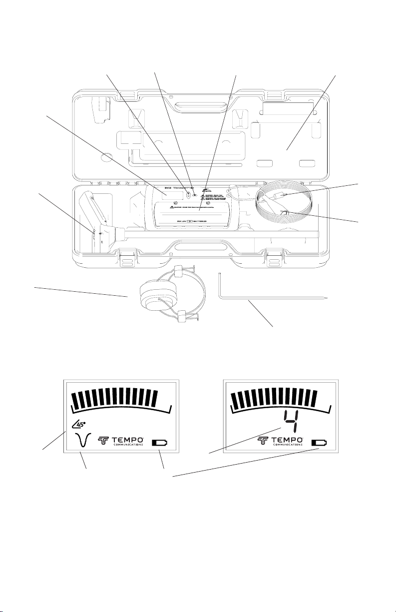
Part Identication ................................................................................................... 5
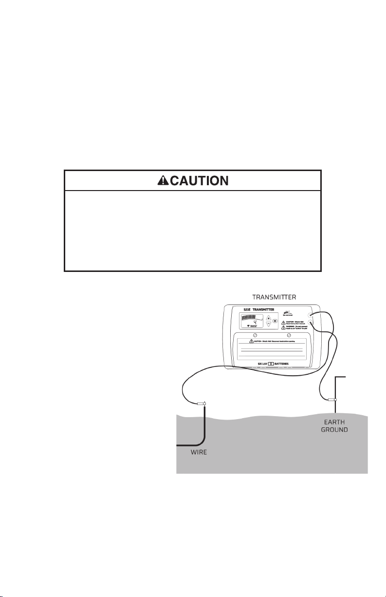
Setup ............................................................................................................................ 6
Operation .................................................................................................................... 7
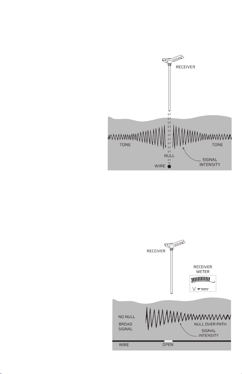
Locating a Wire Path ........................................................................................ 7
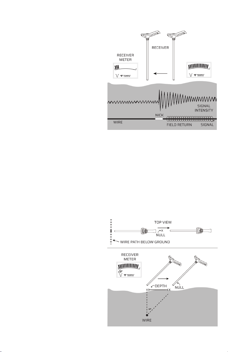
Finding Wire Breaks and Nicks in Insulation (ground leakage)...... 7
Determining the Depth of a Wire ................................................................ 8
Two-Step Solenoid Valve Locating Process ............................................ 9
Digitally Addressable (Two-Wire) Systems............................................. 9
Specications ........................................................................................................... 11
Maintenance ............................................................................................................. 11
Battery Replacement ....................................................................................... 11
Cleaning ................................................................................................................. 11
Description
Tempo Communications Inc. has designed the 521E “Wire and Valve Locators” to aid irrigation
technicians and troubleshooting experts in diagnosing trouble with electronic irrigation control cables.
The uses for this tool include fault identication, fault location, cable location and valve location. 521E
may be used for other similar applications but be aware of potential hazards.
Purpose of this Manual
The purpose of this manual is to familiarize you with the safe operation and maintenance procedures
for the 521E Wire and Valve Locator.
Keep this manual available to all personnel. The latest manuals are always available for download from
our website. We aim to keep this manual up to date with product changes.
Warranty
Tempo Communications Inc. warrants to the original purchaser of these goods for use that these products will
be free from defects in workmanship and material for one year. This warranty is subject to the same terms and
conditions contained in Tempo Communications Inc.’s standard one-year limited warranty.
For all Test Instrument repairs, contact Customer Service at +1 800-642-2155 and request a Return
Authorization. Or complete the form at: www.tempocom.com/returns.
For items not covered under warranty (such as items abused, dropped, soaked, etc.), a repair cost quote is
available upon request.
Note: Prior to returning any test instrument, please check batteries are charged and follow any instructions
given by Tempo’s customer support.
All specications are nominal and may change as design improvements and software updates occur. Tempo Communications Inc.
shall not be liable for damages resulting from misapplication or misuse of its products.
CableScout and TestWizard are trademarks of Tempo Communications Inc.
Do not discard this product or throw away!
For recycling information, go to www.TempoCom.com.
KEEP THIS MANUAL

521E Instruction Manual3
Tempo Communications
Safety
Safety is essential in the use and maintenance of Tempo tools and equipment. This
manual and any markings and indications on the tool including warnings, supply
information for avoiding hazards and unsafe practices related to the use of this tool.
Observe all the safety information provided.
IMPORTANT SAFETY INFORMATION
SAFETY ALERT SYMBOL
This symbol is used to call your attention to hazards or unsafe practices which
could result in an injury or property damage. The signal word, dened below,
indicates the severity of the hazard. The message after the signal word provides
information for preventing or avoiding the hazard.
Immediate hazards which, if not avoided, WILL result in severe injury or death.
Hazards which, if not avoided, COULD result in severe injury or death.
Hazards or unsafe practices which, if not avoided, MAY result in injury or property
damage.
Read and understand this material before operating or servicing
this equipment. Failure to understand how to safely operate this
tool could result in an accident causing serious injury or death.
Electric shock hazard:
Contact with live circuits could result in severe injury
or death.

521E Instruction Manual 4
Tempo Communications
IMPORTANT SAFETY INFORMATION
Electric shock hazard:
• Intended for tracing disconnected circuits. At higher output levels, tracing
signal, if applied across electronic devices, may cause permanent damage.
• Do not touch the exposed end of the test leads or cable being traced unless the
transmitter is o.
• Do not expose this unit to rain or moisture.
• Use this unit for the manufacturer’s intended purpose only, as described in this
manual. Any other use can impair the protection provided by the unit.
• Use test leads or accessories that are appropriate for the application. Refer to
the category and voltage rating of the test lead or accessory.
• Inspect the test leads or accessory before use. They must be clean and dry, and
the insulation must be in good condition.
• Before opening the battery cover, remove the test leads from the circuit and
shut o the unit.
Fire / Explosion hazard:
Do not use this tool in an explosive atmosphere or connected
to wires entering an area with explosive atmosphere. Failure
to heed this warning could result in severe injury or death.
Electric shock hazard:
• Do not connect the transmitter to any active circuits.
• Avoid listening to the receiver through the headset at high
volume levels for more than a few seconds at a time. Use
only the Tempo recommended headset.
Servicing:
• There are no user serviceable parts within 521E, do not
disassemble.
• High voltages can be present inside the transmitter.
• Contact Tempo’s Support Team (details below)
Failure to observe these precautions may result in injury and
can damage the instrument or connected equipment.
RECEIVER DISPLAY

521E Instruction Manual5
Tempo Communications
Part Identication
Display Indicators
1. Headset
2. Ground stake
3. Transmitter
4. Receiver
5. Carrying case
6. Black lead
7. Red lead
8. Output level buttons
9. ON/OFF switch
10. Battery cover
11. 45 degree angle detector
12. Null
13. Low Battery Warning*
14. Output Level
RECEIVER DISPLAY
11.
12. 13.
1.
3.
10.9. 5.
6.
7.
4.
2.
8.
TRANSMITTER DISPLAY
14.
*When transmitter battery is low
receiver tone cadence will change until
battery is replaced.

521E Instruction Manual 6
Tempo Communications
Setup
CAUTION: The transmitter can produce hazardous voltages. Turn the
transmitter OFF before handling the output leads. Disconnect all wires from
the irrigation controller when fault nding.
Before starting you must ensure that the transmitter is set up properly.
IMPORTANT: To ensure that the transmitter is producing optimum signal,
check that the low battery symbol is not visible. Range may be impaired if
signal is low.
Where possible ground the far end
of the cable to be found. You will
need to use higher output levels if
this cannot be achieved.
With the transmitter OFF, connect
the red lead to the wire to be
located and the black lead to a
good earth ground using the stake
provided. Refer to gure 1.
If the clock/controller is indoors,
the earth ground stake should be
placed near the point where the
cables leave the building. It may
require temporarily running a
length of wire to the outside. Never
use a building ground such as a
water pipe or electrical ground.
Now activate the transmitter by pressing the power button for about
one second. Observe the transmitter current indicator and increase the
output level (up button), setting levels 1, 2, 3, 4 or 5 until the gauge reads
somewhere in the middle (approximately 30% to 70% of full scale). If 30%
is not obtainable, you may not have enough of a ground fault or leakage to
ground to locate the entire length of the wire (hence why grounding the far
end is advantageous if it can be done).
IMPORTANT SAFETY INFORMATION
Electric shock hazard:
• Do not connect the transmitter to any active circuits.
• Live circuits can present a hazards to the user and equipment.
• Tracing signal may present a hazard to connected devices. Disconnect all
electronic devices where possible.
Failure to observe these precautions may result in injury and can damage the
instrument or connected equipment.
Figure 1. Transmitter Setup

521E Instruction Manual7
Tempo Communications
Plug the optional headset into the receiver if desired. Turn on the receiver
and point the antenna towards the transmitter to check both are operating as
normal. You should hear a pulsing tone through the speaker or headset and
see signal strength on the scale.
Operation
Locating a Wire Path
With the probe pointed towards
the ground, walk completely
around the transmitter location.
You will hear a peak as you
approach the path of the wire,
a distinct “null” directly over the
wire and another peak as you
pass to the other side of the wire.
Follow the “null”; moving the
antenna to either side of the wire
will cause the level of the tone
detected to increase. The null
allows you to follow the cable
precisely. See Figure 2.
Finding Wire Breaks and Nicks in Insulation (ground leakage)
When attempting to nd breaks and nicks, you should decrease the sensitivity of
the receiver when pointing it o to either side of the null. You will be able to notice
the change in signal intensity immediately. Do not allow the meter to “peg” (show
full-scale). This will greatly help in the fault locating process.
Note: The wire must have a path to
ground to be successfully located.
These paths exist in a great
majority of all direct buried wires
due to insulation imperfections,
nicks, and bad splices. If not, create
one by grounding the remote end.
• The end of a cut or broken wire
can be located by following the
path until the null becomes less
distinct or disappears and gives
way to a “hot spot”. Beyond the
“hot spot”, no null can be detected.
Back up until the null is detected,
and this will be the approximate
end of the broken wire. (Refer to
Figure 3.)
Figure 2. Locating Wire Path
Figure 3. Locating End of Broken Wire

521E Instruction Manual 8
Tempo Communications
Larger nicks in the wire can be
located in almost the same way
as locating opens. Follow the
null and strong signal along the
sides of the wire until the signal
becomes very weak along the
sides of the null. This will occur
within a relatively short distance.
The transmitted signal bleeds to
ground at the nick and then wants
to return to the ground stake along
the outside of the wire itself. The
majority of signals will stop at the
nick indicated by the low receiver
reading just beyond the nick. (Refer
to Figure 4.)
• To more accurately dene the location of an open or larger nick (ground
fault), position the receiver tip on the ground near the point where the last
strong signal was detected along the side of the path. The receiver tip should
be pointing at the ground and be approximately 6 inches to either side
from the null. Because you are so much closer to the path, the sensitivity
knob must be adjusted down until the meter reads just below 100%. While
maintaining the 6-inch distance from the null, move the receiver down the
line, paying close attention to the meter reading. Once you pass the open or
nick, the meter will fall o rapidly.
Determining the Depth of a Wire
To determine the depth of the
wire, rst mark the ground directly
over the path. Turn the receiver
sideways to the path, and tip it 45
degrees. When close to 45 degrees
from the vertical the “45 degree”
indicator will illuminate in the
display. Move the receiver directly
away from the pre-marked path,
maintaining the 45-degree tip until
a null is detected. Mark this spot.
If possible, repeat on the opposite
side of the route. The depth is the
average of the distances between
the path of the cable and each of
the marks. (Refer to Figure 5.)
Figure 4. Locating Wire Nick
Figure 5. Determining Depth

521E Instruction Manual9
Tempo Communications
Figure 5. Determining Depth
Two-Step Solenoid Valve Locating Process
Solenoid valves can easily be located provided all the wires leading to them
are intact and the solenoid itself is still good.
Step 1. Start at the clock. Connect the red transmitter lead to the station wire
leading to the subject valve, and connect the black lead to earth ground.
Turn the transmitter on, adjust the output to the highest level, assemble the
receiver, locate the path, and start tracing the wire following the null. The null
will be present until you pass over a solenoid valve, and then the signal will
become extremely strong.
Mark this spot. Check around this hot spot for a null leaving the area. If the null
continues, follow it and mark any additional hot spots. (Refer to Figure 6.) If
only one hot spot or valve is located, it will be the valve in question.
Step 2. If more than one hot spot is found, mark them and return to the
transmitter and turn it o. Lift the black lead from the ground stake and
connect it to the common wire. Turn the transmitter on, set the selector knob
to the highest reading, and return to the rst hot spot with the receiver. Touch
the tip of the receiver antenna to the ground in the center of the rst hot spot
and set the sensitivity knob to read near mid-scale. Now go to the second spot
and without touching the sensitivity knob, check the strength of the signal at
each hot spot and determine which, out of all of them, is the strongest signal.
This is the valve for the station wire you are connected to.
Digitally Addressable (Two-Wire)
Systems
521E can be used with digitally
addressable irrigation wiring but it
is wise to apply a few rules to avoid
damaging decoders. Decoders are
designed to be tough enough to
withstand normal surges and spikes
that can be present on wiring buried
in the soil, but the direct application
of the 521E maximum output voltage
may cause damage. Damage like this
can be avoided by applying a few
simple tips.
When it comes to using locators on
2-Wire irrigation systems, whether
you use the 501 Tracker II Cable Locator or 521E Wire and Valve Locator to
trace the 2-Wire path, the best practice is always to disconnect from the
controller and clip one transmitter lead to both decoder wires together, then
clip the other transmitter lead to a ground stake pushed into the ground
(ideally o to the side of the route of the cable). This ensures the best signal
and is safest for decoders.
Figure 6. Locating Broken Wire End

521E Instruction Manual 10
Tempo Communications
When the output wire of the transmitter is connected to BOTH lines of the two-wire
circuit, then the transmitter output is common to both wires and provided there
are no signicant faults, then the same voltage is seen on BOTH terminals of each
decoder, eectively placing a completely safe ZERO volts across the decoder.
Note: When using the 521E Wire and Valve Locator to trace 2-Wire cable, it is
always best to use the lower output levels on the transmitter as it can be damaging
to decoders to go higher even when correctly connected if there are certain fault
conditions present.
INCORRECT CONNECTION

521E Instruction Manual11
Tempo Communications
Specications
Transmitter frequency: 1750 Hz
Maximum transmitter voltage: 2500 mW into 1 kohm
Case dimensions: 28” x 12.6” x 4.1” (711mm x 321mm x 104mm), 5.7 lb (2.6 kg)
Transmitter dimensions: 10.4” x 6.7” x 2.3“ (263mm x 171mm x 59mm), 2.6 lb (1.2 kg)
Receiver dimension: 26.1” x 10.1” x 3.5” (664mm x 257mm x 88mm), .75 lb (.3 kg)
Headset sound pressure level: 96±3 dBA SPL max (when used with Tempo supplied headset)
Transmitter battery: 6 x D cells (alkaline recommended), typical life, 50 hours
Automatic shut o: 3 hours
Receiver battery: 4 x AA cells (alkaline recommended), typical life, 50 hours.
Automatic shut o: 1.5 hours
Maintenance
Electric shock hazard:
Contact with live circuits could result in severe injury or death.
• Before opening the battery cover, remove the test leads from the circuit and shut o the unit.
Failure to observe this warning could result in severe injury or death.
Battery Replacement
1. Turn o the unit.
2. Disconnect any leads.
3. Remove the battery cover (see gure 7)
4. Replace the batteries (observing the
polarity indications).
5. Replace the battery cover.
Recycle the old cells.
Cleaning
When necessary, wipe with a cloth dampened with mild aqueous detergent
solution only. Do not use abrasives or solvents. Dry before use.
Figure 7. Battery Replacement

521E Manual de instrucciones
13
Tempo Communications
MANUAL DE INSTRUCCIONES
521E™
Localizador de Cables y Válvulas
Lea y comprenda las instrucciones de uso y la
información de seguridad antes de utilzar esta
herramienta. Para recibir actualizaciones sobre este
producto y su uso regístrese en www.tempocom.com
55505031 REV0 © Tempo Communications 2023 12/23

521E Manual de instrucciones 14
Tempo Communications
Table of contents:
Descripción..................................................................................................................... 14
Propósito del Manual................................................................................................. 14
Garantía........................................................................................................................... 14
Seguridad ....................................................................................................................... 15
Información de seguridad importante ............................................................ 15
Detalles del contacto .................................................................................................. 16
Identicación de pieza................................................................................................ 17
Conguración................................................................................................................. 18
Operación......................................................................................................................... 19
Localización de ruta de cable............................................................................... 19
Encontrar roturas de cables y mellas en el aislamiento (fuga a tierra) 19
Determinar la profundidad de un cable........................................................... 20
Proceso de localización de válvulas selenoides de dos pasos............... 21
Sistemas direccionables digitalmente (de dos hilos)................................. 22
Especicaciones........................................................................................................... 23
Mantenimiento............................................................................................................. 23
Reemplazo de batería ........................................................................................... 23
Limpieza ..................................................................................................................... 23
Descripción
Tempo Communications Inc. Ha diseñado los “Localizadores de válvulas” 521E para ayudar al riego.
Técnicos y expertos en resolución de problemas en el diagnóstico de problemas con cables de control
de riego electrónico. Los usos de esta herramienta incluyen identicación de fallas, ubicación de cables
y válvulas. El 521E se puede utilizar para otras aplicaciones similares, pero tenga en cuenta los peligros
potenciales.
Propósito de este Manual
El propósito de este manual es familiarizarlo con los procedimientos de operación y mantenimiento
seguros.Para el localizador de válvulas y cables 521E.
Mantenga este manual a disposición de todo el personal.Los manuales más recientes siempre estan
disponibles para descragar desde nuestro sitio web.Nuestro objetivo es mantener este manual
actualizado con los cambios de producto.
Garantía
Tempo Communications Inc. garantiza al comprador original, que los productos estan libres de defectos de
mano de obra y material durante un año. Esta garantía esta sujeta a los mismos términos y condiciones
contenidas en la garantía limitada estándar de un año de Tempo Communications Inc.
Para todas las reparaciones de instrumentos de prueba comuníquese con Servicio al Cliente al +1 800-642-
2155 y solicite una Autorizacion de devolución. O complete el formulario en www.tempocom.com/returns.
Para artículos no cubiertos por la garantía (como artículos maltratados, caídos, mojados, etc.) se encuentra
disponible una cotización del costo de reparación previa solicitud.
Nota:Antes de devolver cualquier instrumento de prueba, veríque que las baterías esten cargadas y siga las instrucciones
proporcionadas por el servicio de atención al cliente de Tempo.
Todas las especicaciones son nominales y pueden cambiar a medida que se realicen mejoras de diseño y
actualizaciones de software.Tempo Communications Inc. no será responsable de los daños resultantes de la
mala aplicación o uso indebido de sus productos.
CableScout y TestWizard son marcas comerciales de Tempo Communications Inc.
¡No deseche este producto ni lo tire!
Para información de reciclaje , dirijase a www.TempoCom.com.
CONSERVE ESTE MANUAL

521E Manual de instrucciones
15
Tempo Communications
Seguridad
La seguridad es esencial en el uso y mantenimiento de las herramientas y equipos
Tempo. Este manual y cualquier marca e indicación en la herramienta incluidas
las advertencias, proporcionan la información para evitar los peligros y prácticas
inseguras relacionadas con el uso de esta herramienta. Observe toda la información
de seguridad proporcionada.
INFORMACIÓN DE SEGURIDAD IMPORTANTE
SÍMBOLO DE ALERTA DE
SEGURIDAD
Este símbolo se utiliza para llamar su atención sobre peligros o prácticas inseguras
que prodrían provocar lesiones o daños a la propiedad.La palabra de advertencia
denida a continuación, indica la agravedad del peligro.El mensaje que sige a la
palabra de advertencia proporciona información para prevenir el peligro.
PELIGRO
Peigros inmediatos que, si no se evitan, PROVOCARÁN lesiones graves o la muerte
ADVERTENCIA
Peligros que, si no se evitan, PODRÍAN provocar lesiones graves o la muerte.
PRECAUCIÓN
Peligros o practices inseguras que, si no se evitan, PUEDEN provocar lesiones o
daños a la propiedad.
ADVERTENCIA
Lea y comprenda este material antes de operar o reparar este
equipo.No comprender como ujtilizar essta herra ienta de forma
segura podría provocar un accidente que cause lesiones graves
o la muerte.
ADVERTENCIA
Peligro de descarga eléctrica:
El contacto con circuitos activos prodría provocar lesiones graves
o la muerte.

521E Manual de instrucciones 16
Tempo Communications
ADVERTENCIA
Peligro de descarga eléctrica:
• Destinado para rastrear circuitos desconectados. En niveles de salida más altos, de señal de
rastreo, si se aplica a través de dispositivos electrónicos puede causar daños permanentes
• No toque el extremo expuesto de los cables, que están siendo rastreados a menos que el
transmisor este apagado
• No exponga la unidad a la humedad o la lluvia.
• Utilice esta unidad únicamente para el propósito previsto por el fabricante como se describe
en este manual. Cualquier otro uso puede perjudicar la protección proporcionada por la
unidad.
• Utilice cables de prueba o accesorios que sean apropiados para la aplicación.Consulte la
categoría y la calsicación del voltaje del cable de prueba o del accesorio.
• Inspeccione los cables de prueba o los accesorios antes de usarlos.Deben estar limpios y
secos, y el aisalamiento debe estar en buen estado.
• Antes de abrir la tapa de la batería retire los cables de prueba del circuito y apague la
unidad.
ADVERTENCIA
Peligro de incendio / Explosión:
No utilice esta herramienta en una atmósfera explosiva o conectada a
cables que ingresan a un área con atmósfera explosiva. No prestar atención
a esta advertencia podría provocar lesiones graves o la muerte.
PRECAUCIÓN
Peligro de descarga eléctrica:
• No conecte el transmisor a ningún circuito activo.
• Evite escuchar el receptor a través de los auriculares a niveles
de volumen altos más de unos pocos segundos seguidos. Utilice
únicamente los auriculares recomendados por Tempo.
Servicio:
• No hay piezas que el usuario pueda reparar dentro de el 521E; no
desarmar.
• Pueden haber altos voltajes presentes dentro del transmisor.
• Comuníquese con el equipo de Soporte de Tempo (detalles a
continuación)
El incumplimiento de estas precauciones puede provocar lesiones y dañar el
instrumento o el equipo conectado.
PANTALLA DEL RECEPTOR
INFORMACIÓN DE SEGURIDAD IMPORTANTE

521E Manual de instrucciones
17
Tempo Communications
Identicación de partes
Indicadores de Pantalla
1. Auriculares
2. Estaca de tierra
3. Transmisor
4. Receptor
5. Estuche de transporte
6. Cable negro
7. Cable rojo
8. Botones de nivel de salida
9. Interruptor de encendido y
apagado
10. Tapa de la batería
11. Detector de ángulo de 45 grados
12. Nulo
13. Advertencia de batería baja*
14. Nivel de salida
PANTALLA DEL RECEPTOR
11.
12. 13.
1.
3.
10.9. 5.
6.
7.
4.
2.
8.
PANTALLA DEL TRANSMISOR
14.
*Cuando la batería del transmisor está baja, la cadencia del tono del
receptor cambiará hasta que se reemplace la batería.

521E Manual de instrucciones 18
Tempo Communications
Conguración
PRECAUCIÓN: El tansmisor puede transmitir voltajes peligrosos.Apague el
ytransmisor antes de manipular los cables de salida.Desconecte todos los
cables del controlador de riego cuando encuentre fallas.
Antes de comenzar debe asegurarse que el transmisor este congurado
correctamente.
IMPORTANTANTE: Para asegurarse de que el transmisor produzca una señal
óptima, verique que el símbolo de la batería baja no sea visible.El alcance
puede verse afectado si la señal es baja.
Siempre que sea possible, conecte
a tierra el extremo más alejado del
cable que se encuentre.Necesitará
ujtilizar los niveles de salida mas
altos si esto no se puede lograr.
Con el transmisor apagado conecte
el cable rojo al cable que se va
a ubicar y el cable negro a una
buena tierra usando la estaca
proporcionada. Consulte la gura 1.
Si el reloj/ controlador está en el
interior la estaca de tierra debe
colocarse cerca del punto donde
los cables salen del edicio. Es
posible que sea necesario pasar
temporalmente un trozo de cable
hacia el exterior. Nunca utilice una
toma de tierra de un edicio como
una tubería de agua o una toma de
tierra eléctrica.
Ahora active el transmisor presionando el botón de encendido durante
aproximadamente un segundo. Observe el indicador de corriente del
transmisor y aumente el nivel de salida (botón arriba), congurando los
niveles 1,2,3,4 o 5 hasta que el medidor indique en algún punto intermedio
(aproximadamente del 30% al 70% de la escala completa). Si no se puede
INFORMACIÓN DE SEGURIDAD IMPORTANTE
PRECAUCIÓN
Peligro de descarga eléctrica:
• No conecte el transmisor a ningún circuito activo.
• Circuitos activos pueden representar un peligro para el usuario y el equipo.
• La señal de rastreo puede representar un peligro para los dispositivos conectados. Desconecte todos
los dispositivos electrónicos cuando sea posible.
El incumplimiento de estas precauciones puede provocar lesiones y dañar el instrumento o el equipo
conectado
Figure 1. Conguración del Transmisor

521E Manual de instrucciones
19
Tempo Communications
obtener el 30%, es posible que no tenga suciente falla a tierra o fuga a tierra
para ubicar toda la longitud del cable (de ahí que conectar a tierra el otro
extremo sea ventajoso si se puede hacer).
Conecte los auriculares
opcionales al receptor si así
lo desea. Encienda el receptor
y apunte la antena hacia el
transmisor para comprobar que
ambos funcionan normalmente.
Debería escuchar un tono
pulsante a través del altavoz o
los auriculares y ver la intensidad
de la señal en la escala.
Operación
Localización de una ruta de cable.
Con la sonda apuntando hacia
el suelo, camine completamente
alrededor de la ubicación del
transmisor. Escuchará un pico
a medida que se acerque a la
trayectoria del cable, un “nulo” distintivo directamente sobre el cable y otro
pico a medida que se aleje. Siga el “nulo”; mover la antena a cualquier lado del
cable hará que aumente el nivel del tono detectado. El nulo le permite seguir el
cable con precisión. Ver Figura 2.
Encontrar roturas de cables y
mellas en el aislamiento (fuga a
tierra)
Cuando intente encontrar roturas
y mellas, debe disminuir la
sensibilidad del receptor cuando
lo apunte hacia cualquier lado
del nulo. Podrás notar el cambio
en la intensidad de la señal
inmediatamente. No permita que el
medidor se “je” (muestre
Escala completa). Esto será de gran
ayuda en el proceso de localización
de fallas.
Nota: El cable debe tener un
camino a tierra para poder
ubicarlo correctamente. Estos
caminos existen en la gran
mayoría de todos los cables
enterrados directamente debido a imperfecciones del aislamiento, mellas y
malos empalmes. De lo contrario, cree uno conectando a tierra el extremo
remoto.
Figure 2. Localización de una ruta de cable
Figure 3. Localización del extremo del cable roto

521E Manual de instrucciones 20
Tempo Communications
• El extremo de un cable cortado
o roto se puede localizar siguiendo
el camino hasta que el punto
nulo se vuelve menos distintivo o
desaparece y da paso a un “punto
de foco”. Más allá del “punto de
foco”, no se puede detectar ningún
valor nulo. Retroceda hasta que se
detecte el valor nulo, y este será el
extremo aproximado del cable roto.
(Consulte la Figura 3.)
Las mellas más grandes en el
cable se pueden localizar casi de la
misma manera que las aberturas.
Siga la señal nula y fuerte a lo largo
de los lados del cable hasta que la
señal se vuelva muy débil a lo largo
de los lados del nulo. Esto ocurrirá en una distancia relativamente corta.
La señal transmitida llega a tierra en la mella y luego quiere regresar a la
estaca de tierra a lo largo del exterior del cable. La mayoría de las señales se
detendrán en la mella indicada por la lectura baja del receptor justo más allá
de la mella (Consulte la Figura 4.)
• Para denir con mayor precisión la ubicación de una mella abierta o más
grande (falla a tierra), coloque la punta del receptor en el suelo cerca del
punto donde se detectó la última señal fuerte a lo largo del camino. La punta
del receptor debe apuntar al suelo y estar aproximadamente a 6 pulgadas a
cada lado de lo nulo. Debido a que está mucho más cerca del camino, la perilla
de sensibilidad debe ajustarse
hacia abajo hasta que el medidor
marque justo por debajo del 100%.
Mientras mantiene la distancia de
6 pulgadas desde el punto nulo,
mueva el receptor hacia abajo en
la línea, prestando mucha atención
a la lectura del medidor. Una vez
que pase la abertura o la mella, el
medidor disminuirá rápidamente.
Determinando la profundidad de
un cable
Para determinar la profundidad
del cable, primero marque el suelo
directamente sobre el camino.
Gire el receptor hacia los lados
del camino e incline la punta 45
Figure 4. Localización de mella en el cable
Figure 5. Determinando la profundidad

521E Manual de instrucciones
21
Tempo Communications
grados. Cuando esté cerca de los 45 grados desde la vertical, el indicador
de “45 grados” se iluminará en la pantalla. Mueva el receptor directamente
lejos del camino premarcado, manteniendo la punta a 45 grados hasta que
se detecte un valor nulo. Marque este lugar.
Si es posible, repetir en el lado opuesto del camino. La profundidad es el
promedio de las distancias entre el recorrido del cable y cada una de las
marcas. (Consulte la Figura 5.)
Proceso de localización de válvulas solenoides
de dos pasos
Las válvulas solenoides se pueden ubicar fácilmente siempre que todos los
cables que conducen a ellas estén intactos y el solenoide en sí aún esté en
buen estado.
Paso 1. Comience por el reloj. Conecte el cable rojo del transmisor al cable
de la estación que conduce a la válvula en cuestión y conecte el cable negro
a tierra. Encienda el transmisor, ajuste la salida al nivel más alto, ensamble
el receptor, ubique el camino y comience a rastrear el cable siguiendo el
nulo. El nulo estará presente hasta que pase por encima de una válvula
solenoide, y luego la señal se volverá extremadamente fuerte.
Marque este lugar. Busque en este, algún punto de foco nulo que
abandone el área. Si el valor nulo continúa, sígalo y marque los puntos
de foco adicionales. (Consulte la Figura 6.) Si solo se encuentra un punto
de foco o válvula, será la válvula en
cuestión.
Paso 2. Si encuentra más de un
punto de foco, márquelos, regrese
al transmisor y apáguelo. Levante
el cable negro de la estaca de
tierra y conéctelo al cable común.
Encienda el transmisor, ajuste la
perilla selectora a la lectura más alta
y regrese al primer punto de foco
con el receptor. Toque el suelo con la
punta de la antena del receptor en
el centro del primer punto de foco
y ajuste la perilla de sensibilidad
para que lea cerca de la mitad de la
escala. Ahora vaya al segundo punto
y sin tocar la perilla de sensibilidad,
verique la intensidad de la señal en
cada punto de foco y determine cuál, de todos ellos, es la señal más fuerte.
Esta es la válvula del cable de la estación al que está conectado.
Figure 5. Determinando la profundidad
Figure 6. Localización del extremo del cable roto
Table of contents
Languages:
Popular Control Unit manuals by other brands

CHENGDU VANTRON TECHNOLOGY
CHENGDU VANTRON TECHNOLOGY AP6255 user manual

Westlock
Westlock 1100 Installation and setup manual

Texas Instruments
Texas Instruments CDCM1804 user guide

Move
Move Gateway Pro instruction manual

SMC Networks
SMC Networks S0700 Installation and maintenance manual

Danfoss
Danfoss PVG 100 Service and parts manual