Temspec Air Medic TIF-06 Instruction manual
TIF 06 IOM 2020.0
2360 Millrace Court Tel: (905) 670 3595
Mississauga, Ontario Fax: (905) 670 3592
Canada, L5N 1W2 Web: Temspec.com
Air Medic Air Filtration/ Sterilization Unit
TIF 06 Installation, Operation & Maintenance Manual

i
Contents
List of Tables ...............................................................................................................................................................................................i
1Safety Warnings ............................................................................................................................................................................- 1 -
2Product Overview..........................................................................................................................................................................- 2 -
2.1 Model Number .....................................................................................................................................................................- 2 -
3Operation ......................................................................................................................................................................................- 2 -
3.1 On/Off switch .......................................................................................................................................................................- 2 -
3.2 Filter Clogged Indicator Light ...............................................................................................................................................- 2 -
3.3 Fan Control...........................................................................................................................................................................- 2 -
3.3.1 Variable Speed .................................................................................................................................................................- 2 -
3.3.2 Constant Speed ................................................................................................................................................................- 2 -
4Unit Entry ......................................................................................................................................................................................- 3 -
4.1 Lower Access Panel Lock ......................................................................................................................................................- 3 -
4.2 Lower Access Panel ..............................................................................................................................................................- 3 -
4.3 Upper Access Panel ..............................................................................................................................................................- 3 -
4.4 Motor Access Panel ..............................................................................................................................................................- 4 -
5Air Medic Component Installation, Maintenance and Replacement Instructions........................................................................- 4 -
5.1 Filters....................................................................................................................................................................................- 4 -
5.1.1 Prefilter ............................................................................................................................................................................- 4 -
5.1.2 HEPA Filter .......................................................................................................................................................................- 5 -
5.1.3 Activated Carbon Filter (Optional Accessory) ..................................................................................................................- 5 -
5.2 Casters (Optional Accessory)................................................................................................................................................- 6 -
5.3 UVC Light (Optional Accessory)............................................................................................................................................- 6 -
5.4 Ionizer (Optional Accessory).................................................................................................................................................- 7 -
5.5 Fan Assembly........................................................................................................................................................................- 8 -
5.6 Differential Pressure Switch (Optional Accessory) ...............................................................................................................- 8 -
6Warranty Information ...................................................................................................................................................................- 9 -
7Parts List......................................................................................................................................................................................- 10 -
List of Tables
Table 1: Component Replacement Frequency.......................................................................................................................................- 9 -
Table 2: Unit Specifications....................................................................................................................................................................- 9 -

- 1 -
1Safety Warnings
When operating electrical appliances, basic precautions should be followed.
To reduce risk of fire, electrical shock, or injury:
•Do not use outdoor or on wet surfaces.
•Use only as described in this manual.
•Do not use with damaged cord or plug.
•Do not unplug by pulling on cord. To unplug, grasp the plug.
•Do not handle plug with wet hands.
•Do not put any object into opening.
•Turn off all controls before unplugging.
If the UV lamp is broken do not touch the cell or glass with your hands
UV lamp may be hot and could cause serious burns if not handled properly. Please wait until the
lamp has cooled to room temperature to remove from the unit.
WARNING: UV Light Hazard. Harmful to skin and eyes. Can cause temporary or permanent
loss of vision. Never look at the lamp while illuminated. To prevent exposure to ultraviolet light,
be sure the power is disconnected before servicing.
CAUTION: Ionizer generates high voltage. Make sure the cord is unplugged before cleaning
the ionizer brush heads.
CAUTION: Remove any accumulated dirt on the ionizer brush heads to prevent risk of
flashover or fire.
WARNING: RISK OF ELECTRICAL SHOCK. CAN CAUSE INJURY OR DEATH:
UNPLUG OR DISCONNECT UNIT FROM POWER BEFORE SERVICING.
WARNING
CAUTION

- 2 -
2Product Overview
The Air Medic unit is designed to enhance the air filtration of your primary HVAC system. It does not have the ability to heat or cool
and provides filtration and sterilization only. This unit is not a substitute for other virus spread measures such as frequent hand
sanitization, face masks or 6ft (2m) physical distancing.
2.1 Model Number
For the full model numbers available and product selection options please visit our website at www.temspec.com.
3Operation
The Air Medic Unit has a few different control options depending on the configuration chosen. For all units, the Air Medic must be
plugged into a standard 120V receptacle with ground pin.
3.1 On/Off switch
If the on/ off switch is chosen it will control the power to the
unit once plugged in. The switch will light up when in the “on”
position to indicate power to the unit.
If no switch is selected all devices will have power as soon as
the unit plugged in.
3.2 Filter Clogged Indicator Light
An optional filter clogged indicator light is available. This light
is connected to the differential pressure switched. This
pressure switch measures the air pressure around the HEPA
filter and when it is too high the indicator light will come on to
warn the user it should be changed.
This is only a warning indicator. The unit will continue to work
with it on, but the airflow will be decreased due to the dirty
filter.
3.3 Fan Control
The fan control is available in either variable speed or constant
speed configurations. The speed of the fan directly relates to
the amount of airflow.
3.3.1 Variable Speed
Variable speed motor control allows the user to directly
control the fan speed from the face of the unit. Turning the dial
clockwise increases the speed, and counterclockwise slows the
fan down. Turning the dial all the way counterclockwise you
will hear a click, which will turn the fan off, as well as the UVC
light and Ionizer (if applicable).
.
3.3.2 Constant Speed
Constant speed control allows the unit to run at a single speed
when it is turned on, with no outside adjustment.
Inside of the electrical chamber, there is a speed board which
will allow the user to turn up or down the fan speed to the
desired set point. The speed board is controlled by turning the
dial clockwise to increase and counterclockwise to decrease.
The adjustment can be done with a small slot terminal
screwdriver.
- 3 -
4Unit Entry
There are two separate access panels located at the back of the unit
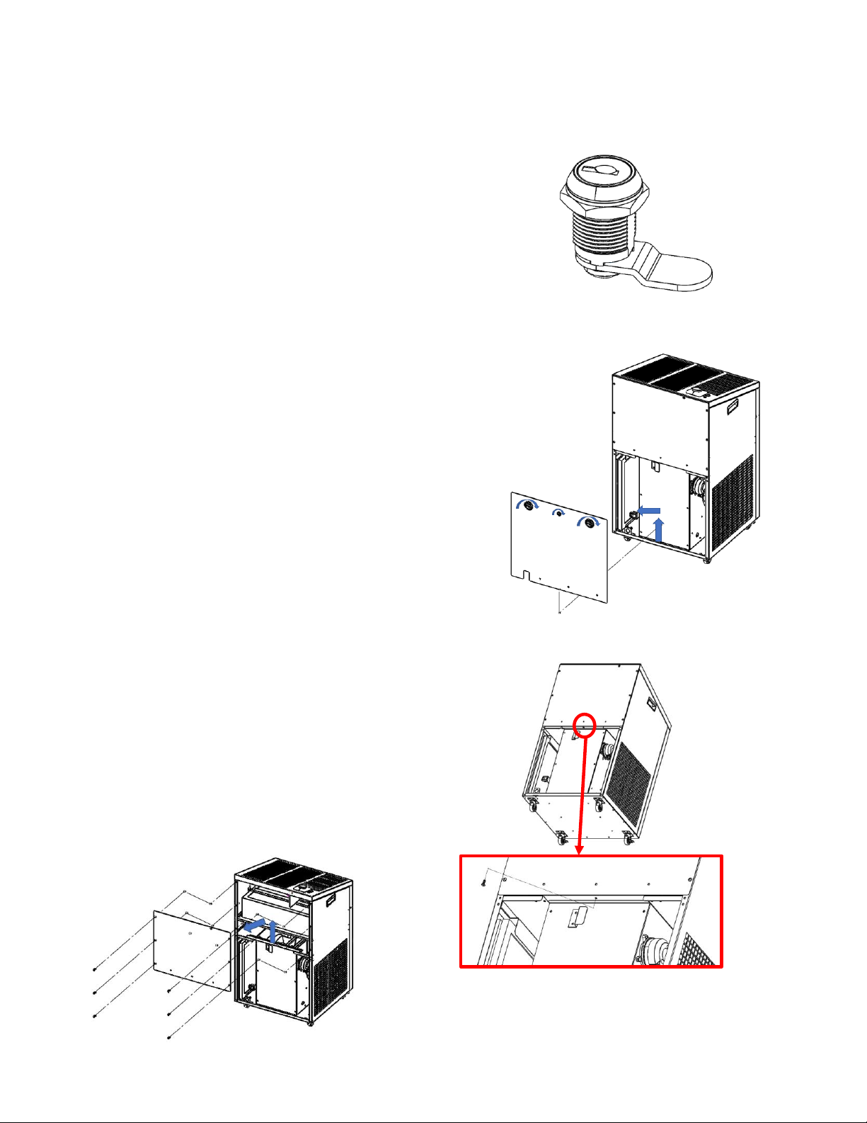
4.1 Lower Access Panel Lock
The Air Medic have a Keyed Cam Lock as an optional accessory.
This lock is located on the upper middle of the lower access
panel. The key allows the unit to be locked to avoid any
unwanted entry and tampering of the unit.
4.2 Lower Access Panel
The lower access panel is the main access into the unit. this is
the panel that allows the user to access the Prefilter and the
Activated Carbon Filter. This panel is equipped with a door
microswitch. This switch stops both fans, UVC light, and
Ionizer.
This panel is equipped with two cam latches that turn to lock
in place to secure the panel, and the optional lock mentioned
above.
To open the lower access panel, unlock the cam lock, turn the
cam latches to the unlocked position and then pull up and out.
When replacing the panel, align the panel with the width of the
unit and slide it down onto the hook at the bottom. Make sure
not to damage the power cable.
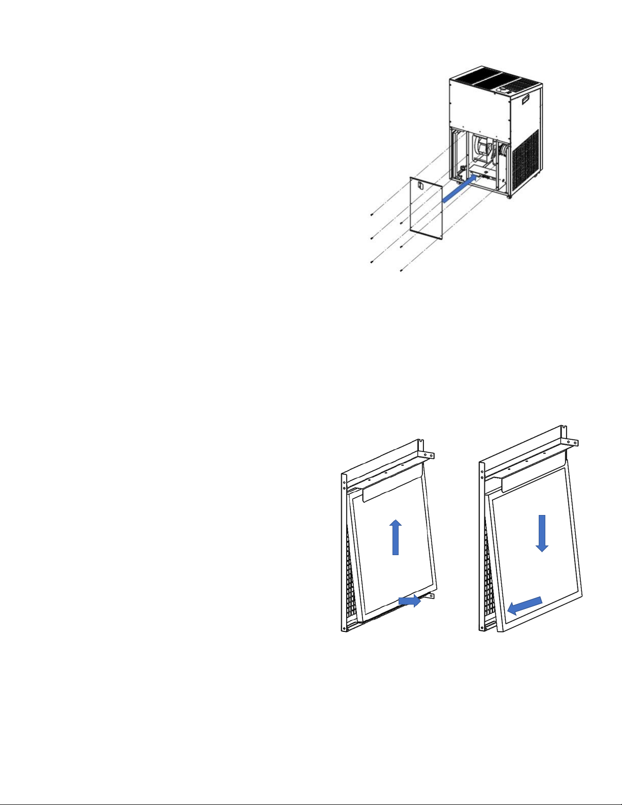
4.3 Upper Access Panel
The upper access panel allows access the HEPA filter, UVC light,
and Ionizer.
This panel removed by undoing the screws located on the back
panel. There is one screw located on the bottom of the panel
only accessible with the lower panel removed. This is to ensure
all electrical devices in the unit are stopped while it is open.
Remove the panel by lifting off the guide hook and pulling
towards you.
- 4 -
4.4 Motor Access Panel
This panel is located behind the lower access panel and
contains the latch for the cam lock. This panel can be removed
simply by removing the screws that hold it to the fan
bulkheads.
5Air Medic Component Installation, Maintenance and Replacement
Instructions
CAUTION: Before attempting to service the unit, be sure the power is off and unplugged
5.1 Filters
5.1.1 Prefilter
5.1.1.1 Description
The Air Medic comes standard with two 1-inch Prefilters
installed on the air intakes of the units. They are standard
MERV 10 filters designed to catch the initial dust and dirt
particles before they can get inside of the Air Medic, similar to
your HVAC equipment.
5.1.1.2 Replacement Frequency
The replacement frequency for the Prefilters can be found in
Table 1.
5.1.1.3 Replacement Instructions
To replace the Prefilters when they are dirty, they need to be
removed. To remove the Prefilters, the lower access panel
must be removed. Lift out of the lower guide, pull in to clear
the guides, push down to clear the upper guides and then pull
out of the unit.
To install the new filter, first ensure that the airflow arrow on
the filter is pointing towards the middle of the unit.
Note: if the unit has Activated Carbon filters installed, they
must be removed first before removing the Prefilter. See
below for Activated Carbon filter removal
.
- 5 -
5.1.2 HEPA Filter
5.1.2.1 Description
The Air Medic comes standard with a 6-inch HEPA (High
Efficiency Particulate Air) filter. This filter is designed to stop at
least 95% of all particles 0.3µm or larger. This is same level of
filtration as N95 masks.
5.1.2.2 Maintenance Interval
The unit is equipped with a filter change light that will
indicated when the HEPA filter should be changed. The
standard replacement frequency for the HEPA filter can be
found in Table 1.
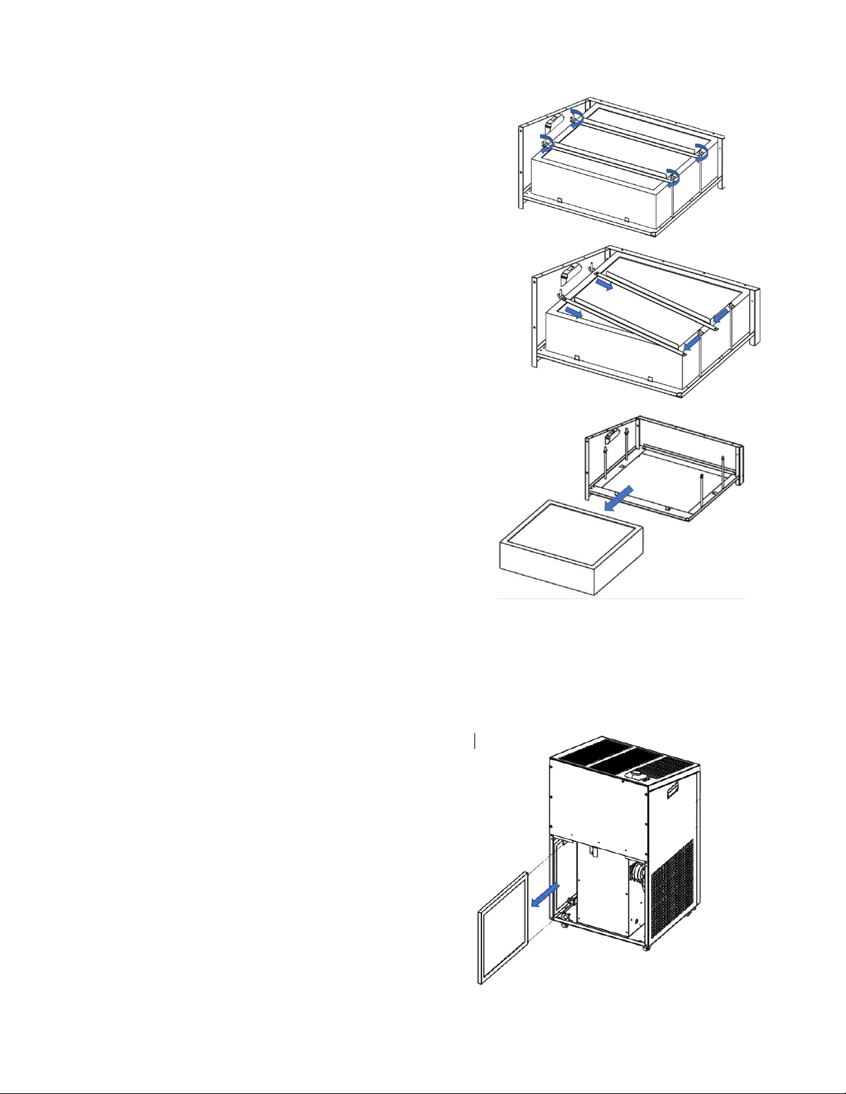
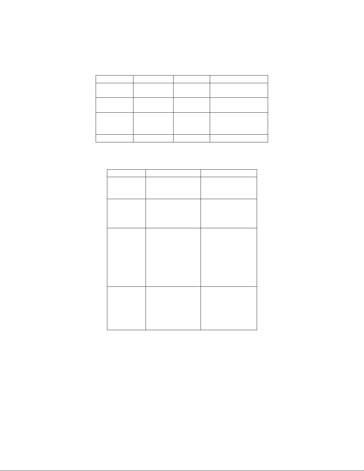
5.1.2.3 Replacement Instructions
To access the HEPA filter, remove the upper and lower access
panels. The HEPA filter is held to the bulkhead by two brackets.
These brackets can be removed by loosening the wingnuts and
turning the brackets so that they come free of the threaded
rods. The HEPA can then be lifted and removed. When
inserting the new HEPA make sure the airflow arrow is pointing
up, and the HEPA is sitting flat on the bulkhead. Put the
brackets back in place on the threaded rods and then tighten
the wingnuts.
5.1.3 Activated Carbon Filter (Optional Accessory)
5.1.3.1 Description
An optional accessory for the Air Medic is two 1-inch Activated
Carbon Filters. These filters make use of Activated Carbon to
adsorb airborne particles to help with allergens and odours.
5.1.3.2 Installation Instructions
The Activated Carbon filters are installed on the intakes behind
the Prefilters. To install the new filter, first ensure that the
airflow arrow on the filter is pointing towards the middle of the
unit. Slide the filter in lower into the upper and lower guides,
ensure it is pushed all the way to the bottom. The Activated
Carbon filter should be installed in the inner most filter slot.
Note: the Prefilter should be installed before the Activated
Carbon filter.
5.1.3.3 Maintenance interval
The replacement frequency for the Activated Carbon filter can
be found in Table 1.
5.1.3.4 Replacement Instructions
To replace the Activated Carbon filters when they are dirty,
they need to be removed. To remove the Carbon filters,
remove the lower. Pull the Carbon filter toward you and out of
the unit.
The installation of new filters is the same as listed above.
- 6 -
5.2 Casters (Optional Accessory)
5.2.1.1 Description
The standard option for the Air Medic is rubber foot pads for
stability. An optional accessory for the Air Medic is four swivel
casters, two are locking. These casters add increased
portability and allow the unit to roll around in any direction.
5.2.1.2 Installation Instructions
To instal the casters, first place the unit on its side, be careful
not to scratch the unit. Remove the rubber foot pads by
unscrewing them from the threaded holes on the bottom of
the unit.
Take the supplied casters and align them with the holes in the
corners on the bottom. Ensure the lockable casters are at the
front of the unit for easy access. Screw the base of the caster
to the base of the unit, with the spring washer placed between
the screw head and the caster base.
5.3 UVC Light (Optional Accessory)
5.3.1.1 Description
An optional accessory is the UVC light. This is a fluorescent
style bulb that emits what is known as UVC-GI light wavelength
(UVC-Germicidal Irradiation, 254nm). This light is a very small
wavelength which allows it to penetrate pathogens and
destroy the DNA rendering it inert.
The light is positioned so that it shines on the full face of the
HEPA filter, allowing it to clean filter of anything that gets
caught to it and to lengthen the filter life.
Direct exposure should be avoided as it may cause damage to
skin and eyes.
The UVC light is also supplied with a reflector to ensure that
the UVC light does not have any direct exposure on the fan
assemblies.
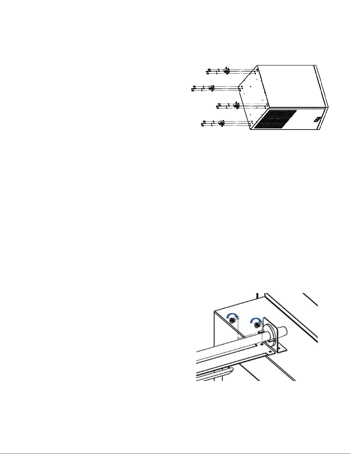
5.3.1.2 Installation Instructions
First remove the lower and upper access panel and then
remove the HEPA filter.
Take the light ballast and align the tabs with the holes on the
right fan bulkhead, closest to the wall of the unit, and screw
them down with the provided Philips head screws.
Take supplied UVC mount assembly and align it with the four
holes (two on each bulkhead) and with the end with the Bulb
mounting bolts on the same side as the ballast. Screw assembly
down with the provided Philips head screws.
Mount the UVC bulb, by inserting the cable through the
mounting bracket. Align the blub base with the mounting bolts
and tighten the supplied nuts. Do not over tighten the nuts.
Connect the bulb to the ballast, and the ballast to the power
supply using the supplied quick connects. Ensure they have a
firm and properly sealed connection, and that the locks have
fully engaged.
5.3.1.3 Maintenance Interval
The replacement frequency for the UVC bulb can be found in
Table 1.
5.3.1.4 Replacement Instructions
To replace the UVC light, only the blub needs to be replaced.
To do this, first remove the lower and upper access panel and
then remove the HEPA filter.
Disconnect the quick connect between the bulb and the
ballast, remove the nuts holding the bulb to the mounting
bracket and remove the bulb and wire from the mounting
bracket.
To reinstall the new bulb, insert the cable through the
mounting bracket. Align the bulb base with the mounting bolts
and tighten the supplied nuts. Do not over tighten the nuts
Reconnect the wiring quick connect between the bulb and the
ballast. Ensure they have a firm and properly sealed
connection, and that the locks have fully engaged.

- 7 -
5.4 Ionizer (Optional Accessory)
5.4.1.1 Description
An optional accessory is the Ionizer. This is a small device that
creates both negative and positive ions into the airstream.
These ions attract and stick to airborne pollutants and harmful
particles. This creates larger clusters in the air which allow
them to be trapped by filters more efficiently. The transfer of
ions between the air and the pollutants in the air also help to
render them inert.
The ionizer is supplied with a cover assembly. This cover is used
to help protect the ionizing brushes from any debris or
cleaning solution falling through the top panel.
5.4.1.2 Installation Instructions
To install the ionizer, first attach the ionizer to the cover
assembly with the provided nuts and bolts. Ensure the brushes
are facing away from the back of the cover assembly, and not
to over tighten the nuts.
Then, remove the lower and upper access panels. Align the
cover assembly with the holes on the outside of the electrical
cover, and mount using the provided Philips head screws.
Attach the ionizer quick connect to the 2-pin quick connect to
the unit quick connect below the electrical cover. Ensure they
have a firm and properly sealed connection, and that the locks
have fully engaged.
5.4.1.3 Maintenance Interval
It is recommended that every six (6) months the ionizer being
inspected for dust or dirt buildup on the brushes or indicator
light.
If there is dust or dirt, it should be removed with compressed
air or small alcohol towelette. Let the alcohol dry before
turning on the unit.
Cleaning sprays should not be used.
If there is any moisture on the brushes when the unit is turned
on, it may cause failure of the ionizer.
5.4.1.4 Replacement Instructions
To replace the Ionizer, first remove the lower and upper access
panel.
Disconnect the quick connect. Undo the nut and bolt holding
the ionizer to cover and remove the device out of the upper
access.
Align the new ionizer with the mounting holes on the cover
assembly with the brushes facing out. Secure the ionizer to the
cover with the nuts and bolts. Attach the ionizer quick connect
to the 2-pin quick connect to the unit quick connect below the
electrical cover. Ensure they have a firm and properly sealed
connection, and that the locks have fully engaged.

- 8 -
5.5 Fan Assembly
5.5.1.1 Description
The air medic comes with two high efficiency backward
inclined fans. These fans modulate their speed based on the
input control signal which varies from 0-10VDC, based on the
controls selected in the Fan Control section.
All controls within the fans are internally sealed and do not
need any maintenance.
5.5.1.2 Replacement Instructions
To replace a fan, first open the lower access panel and then
remove the fan cover. Disconnect the quick connect to the
desired fan. Remove the screws holding the fan to the
bulkhead and then remove the fan through the opening.
To install the new fan, insert into the opening and align the fan
with the holes on the bulkhead. Ensure the fan in oriented in a
way that the fan quick connect will reach the unit quick
connect. Tighten all screws on the fan and then reconnect the
quick connect. Ensure they have a firm and properly sealed
connection, and that the locks have fully engaged.
5.6 Differential Pressure Switch (Optional Accessory)
5.6.1.1 Description
An optional accessory is the differential pressure switch. This
switch measures the pressure around the HEPA filter with the
use of 1/4” tubing to let the operator know when the HEPA
needs to be replaced. When the pressure differential around
the HEPA rises above the recommended level the switch will
close and it will light the amber indicator light on the unit face.
5.6.1.2 Maintenance Interval
The switch is fully sealed and does not need any maintenance
itself.
Every year it is recommended to inspect pressure switch
tubing to ensure they are a not kinked or clogged.
5.6.1.3 Replacement instructions
To replace the Differential Pressure Switch, first remove the
lower access panel, and then disconnect the tubing attached
to switch. Unscrew the switch from the bulkhead, removing
the Prefilter and Activated Carbon Filter on that side my allow
for easier access. Once the device is loose, open the cap and
disconnect the wiring inside, then remove them from the
switch.
Open the remove the cap from the new switch, adjust the dial
to 2-inch WC, feed the wires into the switch and attach them
to terminals 2&3. Attach the cap and mount the switch to the
bulkhead, ensure the tube ports are pointed down. Reattach
the tubes, with the tube going below the HEPA on port 1, and
the tube going above the filter onto port 2.
- 9 -
6Warranty Information
All Air Medic units carry a parts only warranty for a period of 1 year from date of shipment.
For all Warranty and Part Sales queries please visit Temspec.com or call 888-836-7732.
Table 1: Component Replacement Frequency
Size
Part No.
Change Frequency
Prefilter
16” x 18” x 1”
MERV 8
FPY 16118
3-6 months
H.E.P.A 95
Filter
18” x 20” x 6”
MERV 16
FPH 18620
2 years or when
indicator is lit
Activated
Carbon
Filter
16” x 18” x 1”
MERV 7
FPC 16118
1 year
UVC Light
16 Watt
EUL 01516
1 year
Table 2: Unit Specifications
TIF- 06
TIF-08
Performance
450 CFM
600 CFM Purge
Mode
450 CFM
800 CFM Purge
Mode
Electrical
120 VAC
2.6 FLA
6ft, 2m Power cord
120 VAC
3.4 FLA
6ft, 2m Power cord
Fan & Motor
250mm Backward
Inclined Impeller
fan with ECM
20 –100% fan
modulation
600C FM @ 1.2”
TSP
285/s @ 300pa
280mm Backward
Inclined Impeller fan
with ECM
20-100% fan
modulation
800 CFM @ 1.2” TSP
375/s @ 300pa
Physical Data
36”H x 20” W x 22”
D
915mm x 510mm x
560mm
Weight: 95lbs, 43kg
52”H x 20” W x 26”
D
1320mm x 510mm x
660mm
Weight: 95lbs, 43kg

- 10 -
7Parts List
UVC Bulb
EUL 01516
IONIZER
EIN 02400
IONIZER COVER
FUM 9060
PRE-FILTER
FPY 16118
ON/OFF
SWITCH
ESX 10012
CARBON
FILTER
FPC 16118
INDICATOR
LIGHT
EIL 12003
HEPA
FILTER
FPH 18620
VARIABLE SPEED
FAN CONTROLLER
EMC 09004
CONSTANT SPEED
FAN CONTROLLER
EMC 09003
DOOR INTERLOCK
SWITCH
ESX 08000
DIFFERENTIAL
PRESSURE
SWITCH
ESD 22000
CASTER WHEELS
LOCKING
WCX 51608
CASTER WHEELS
WCX 51608
LIFT HANDLE
VHX 01004
KEYED CAM
LOCK
NXL 01008
FAN
BFE 025017
3/4IN FAN SCREW
NSL 00306
IONIZER NUT
NNX 21024A
UVC THUMB
NUT
NNT 00202
CAM LOCK
NXL 01010
3/4IN SCREW
NSH 10206
1/2IN SCREW
NSL 00304
CASTER LOCK WASHER
NWX 21008
CASTER BOLT
NBH 00405
This manual suits for next models
1
Table of contents


