Ten-Tec 1254 User manual

Ten-Tec 1254 Receiver Processor Upgrade Installation
Overview
The upgrade kit adds to a Ten-Tec 1254 shortwave radio receiver finer step frequency tuning,
more memory channels, new radio features, and removal of the need for a backup battery It
does this by replacing the radio's PIC processor with new firmware in a new Cypress processor
mounted on a daughter board to fit the radio's existing processor socket An auxiliary circuit
board, cables, and new aluminum rear panel add a line level audio output, and a computer CAT
computer control interface This computer interface is configured as either an RS-232 or mini-
USB connection
The upgrade kit does not change the radio as supplied by Ten-Tec in it's construction or
alignment procedures The alignment can be done with either processor
1254 Upgrade Kit Contents
•Precision laser cut aluminum rear panel with mounted auxiliary interface board, 3 5mm line
level output jack, computer communications connector with transmit and receive status LEDs,
and AGC level input connector
•Cypress processor mounted on a daughter board with components for analog and digital
interfaces
•Shielded analog audio input coax to connect the processor board to the radio's main board
•Optional Ten-Tec 1254 display board mounted single auxiliary LED 1
•Ribbon cable to connect the processor board to the auxiliary interface board
•AGC tie in wire and connector from the radio's main board to the auxiliary board
1 The additional LED supplied in the kit that can be installed in an existing, but unused location on the
display board.
Upgrade Kit Installation
The processor daughter board is pre-
assembled and ready to place on the radio's
main circuit board Carefully remove the
PIC processor, if already installed Next
take the coax cable supplied with the kit
and snap into connector X1 on the daughter
board so that the cable is pointing away
from the processor Feed the cable's free
end around the front of the radio main
board where it can be later soldered to the
audio amplifier chip input pin (see
installation photos below) Line up the pins 1 to 1 from the main board's processor socket to the
daughter board header and press the new board in place The section of the daughter board that
holds the JP1 flex cable connector must be pointed to the back of the radio Do not install or if
installed remove the 9 Volt battery for the original PIC processor supplied from Ten-Tec It is
not required
An auxiliary communication interface
circuit board is mounted to a new rear
aluminum panel as an assembly To install
the new assembly first remove the speaker
from the radio by removing the four flat
head black screws and unplugging the
speaker wire connector from the main radio
board The original rear aluminum panel on
the radio is then removed and replaced with
the auxiliary board and panel assembly
Before screwing on the new rear panel to the radio chassis insert and lock in the flex cable The
blue part of the flex cable is inserted facing the moveable part of the flex cable connector Feed
flex cable under the auxiliary board and behind the main radio board The other end of the flex
cable is then inserted into the connector on the processor daughter board
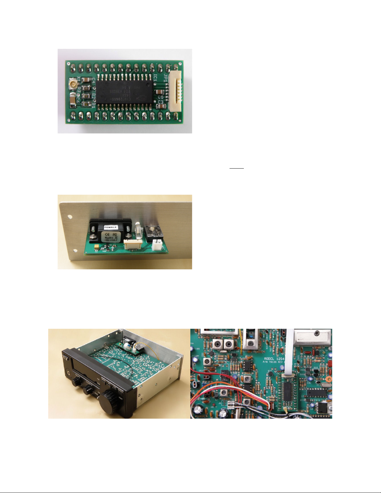
AGC Pic up Connection
The AGC voltage level from the radio's
main board is used to determine the
signal strength which is read over the
computer control interface Take the
yellow wire with the two pin JST
connector and plug it into the auxiliary
board's two pin receptacle Feed the
wire around the back of the radio main
board to the top side of the board
Solder the free end of the yellow wire to
resistor R66, either side (see assembly
photos)
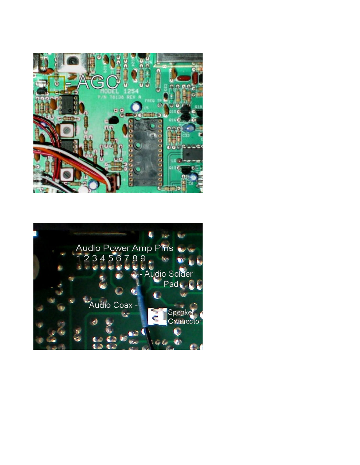
Audio Pic up Connection
Low level demodulated audio from
the radio is amplified and sampled
in the kit's new processor The
shielded audio cable that was
plugged into X1 on the daughter
board and threaded through to the
bottom side of the radio's main
board needs to be soldered to the
main board There is a row of what
looks like 10 pads in a row where
the audio power amplifier is
soldered on to the radio's main
board Note that only 9 of these
pads go to the pins of the amplifier
chip Observe the picture of the
bottom of the board around the
speaker connector and the notch for
the tuning encoder Pin 8 is the solder point for the signal, center conductor, of the shielded
cable Note that it is easier to solder to the pad just behind Pin 8
On the processor daughter board insure that the coax connector does not twist left or right to
short any of the components on the daughter board Plug in the speaker and reattach its
aluminum carrier panel to the radio chassis Complete the installation by replacing the top and
bottom radio covers

Display Circuit Board Auxiliary LED
A LED is provided in the kit for optional installation on the display board This new LED
allows the processor's program to provide additional state information during the radio's
operation Note that it is not required to install this extra LED for the kit's operation Refer to
the Ten-Tec instruction manual page 1245 - Assembly - 7 The new LED inserts in between
diode D5 and D6 in the same orientation in the holes present but unlabeled on the display board

New Radio Features
Frequency Step Size
The radio now tunes in steps of 10, 100, 1000, 1250, 2500, 5000, 9000, 10000, and 100000
Hertz 2 Pressing the SPEED key displays the current tuning step size Rotate the tuning knob to
change the step size Press the SPEED key again to select the new step size The FAST LED
will light as before when you are set to the 100000 frequency step The frequency step is now
independent of the mode setting
Memory Locations
The amount of memory locations has been expanded from 16 to 128 You now can change
modes from memory to VCO retaining the current memory channel frequency and mode by
pressing the MW key
Setup Mode Options
Upon power up and for two seconds you can enter a special radio setup mode by pressing the
MODE key Pressing any other key or tuning the radio immediately terminates the setup waiting
period and returns the radio to normal operation performing the selected action If available the
optionally installed display LED will be lite on power up for the duration of the two second
timeout
Setup mode is indicated by the display showing a “u” followed by the firmware revision
number and by the optional LED being lite In the setup mode the radio keys have alternate
functions
Pressing the MODE key allows you to adjust the communication baud rate to other than the
default 57600 rate using the tuning knob Pressing the mode key again returns to normal use
with the selected rate retained
Pressing the V/M key sets the display refresh rate between fast “c1” and slow “c0” The default
setting is fast Pressing V/M again returns to normal operation Slow should only be used when
using a good regulated power supply Fast is used for minimal radio noise using the Ten-Tec
supplied wall supply
Pressing SPEED allows you to set a new display timeout interval Dial the desired timeout in
seconds using the tuning knob with 0 meaning no timeout, default operation Hit SPEED again
to select the new timeout With a non-zero number is used the display will blank off after the
number of seconds selected if no key is pressed or no new frequency is tuned Any action starts
the display again There is no timeout on memory or frequency select functions Display
blanking is used to remove the possible occurrence of display generated noise, most noticeable
when using unregulated power supplies
2 Exact frequency tuning is obtained over the full receive frequency range from 100 KHz to 30 MHz for all tuning steps
1250 Hz and above Exact 1000 Hz tuning steps are available from 100 KHz to 20 535 MHz PLL tuning solutions to
frequencies with 100 Hz steps between 1 KHz or 1 25 KHz increments must be calculated using a factoring algorithm In
98% of all cases a solution is available for the requested frequency If a solution is not available the frequency is not tuned
Table of contents
Other Ten-Tec Receiver manuals


Popular Receiver manuals by other brands


Sirius Satellite Radio
Sirius Satellite Radio Stream Jockey II XTR2CK instruction manual

DTM System
DTM System cloud FLEX Installation and service manual

taranis
taranis e-soar plus Setup guide

Revox
Revox Joy S119 user manual

Harman Kardon
Harman Kardon AVR 220 Service manual

Yamaha
Yamaha POCKETRAK CX owner's manual


