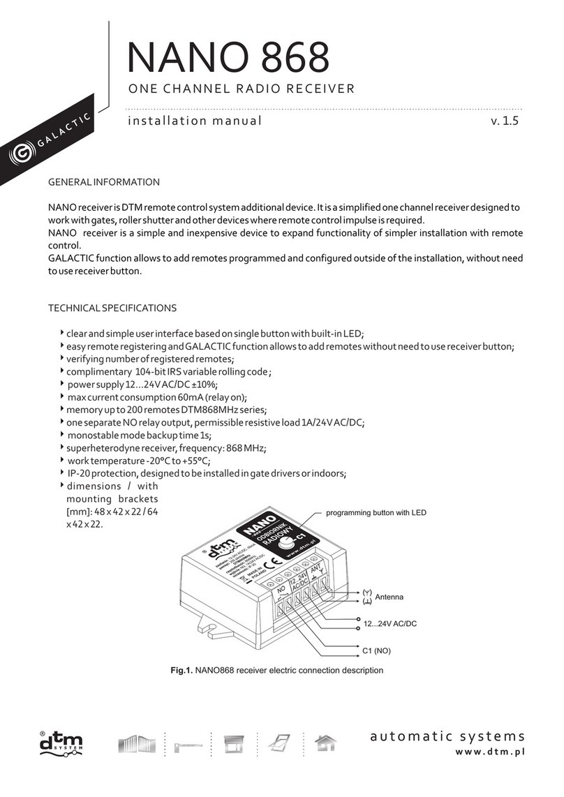
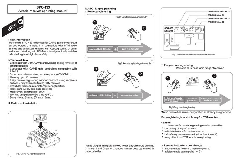
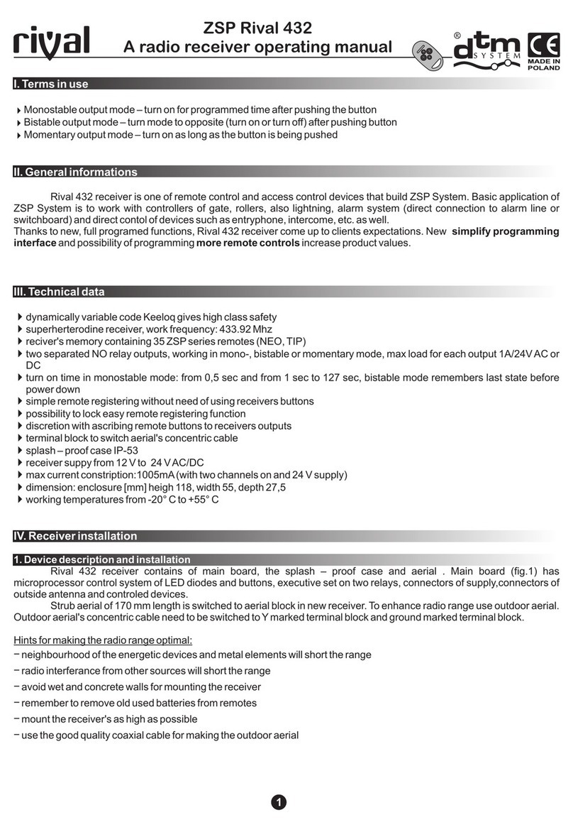
DTM System cloud FLEX Manual

v.1.
3

2
Table of contents
1. General information ....................................................................................................................................................... 4
2. Technical parameters ..................................................................................................................................................... 5
3. Installation and operating mode ..................................................................................................................................... 6
4. Simple assigning /removing of the remote ...................................................................................................................... 7
4.1. ast assigning of the remote button to the channel of the receiver ........................................................................... 7
4.2. ast removing of the connection between the remote button and the channel of the receiver .................................. 7
4.3. Remote assigning of the remote in the radio range of the receiver ........................................................................... 7
4.4. Adding a remote control with the Galactic function ................................................................................................. 8
5. Programming –receiver menu ........................................................................................................................................ 9
5.1. PP option – remote programming /edition ............................................................................................................. 10
5.1.1. New remote programming .............................................................................................................................. 10
5.1.2. Owned remote edition .................................................................................................................................... 10
5.1.3. Remote control edition without its physical presence....................................................................................... 11
5.1.4. CP option – copying of the remote settings from the other remote programmed earlier .................................. 12
5.1.5. Pn option – assigning of the receiver channels to the remote buttons .............................................................. 13
5.1.6. Bc option – individual blockade of remote assigning function .......................................................................... 14
5.1.7. UP sub option – removing the remote from the receiver memory ..................................................................... 15
5.2. PC option –receiver channels programming ........................................................................................................... 16
5.2.1. Bistable and monostable (connection time) programming mode ..................................................................... 16
5.2.2. PC.CH – Pulse mode programming ...................................................................................................................17
5.2.3. PC.2P – Double click function programming .................................................................................................... 18
5.3. LP option –the number of remotes assigned to the receiver ................................................................................... 19
5.4. bd option – main menu access blockade of the receiver (PIN code) ........................................................................ 20
5.5. bc option – global blockade of the remote assigning function ................................................................................. 23
5.6. Sr option - receiver INPUT settings. Manual control mode and status signaling mode. ........................................... 24
5.6.1. Setting of INPUT parameters .......................................................................................................................... 24
5.6.2. Manual control mode ...................................................................................................................................... 24
5.6.3. Status signaling mode ..................................................................................................................................... 24
5.7. Et option – settings of ethernet network ................................................................................................................ 29
5.8. GA option - setting the Galactic function authentication code ................................................................................ 32
5.8.1 Galactic function on / off. Manual input of the authentication code to the receiver ............................................ 32
5.8.2 Setting the Galactic authentication code using the remote control with Galactic function ................................ 32
5.9. HA option - disabling schedules ............................................................................................................................. 34
5.10. Id option – displaying receiver identification ......................................................................................................... 34
5.11. P option – deleting of memory and factory reset. ................................................................................................ 36
6. M2 module ....................................................................................................................................................................37
7. REL-2 / REL-2 PWR optional module ..............................................................................................................................37
7.1. General information ................................................................................................................................................37
7.2. Technical and service data ......................................................................................................................................37

3
8. Optional module of the wireless Wi- i WL2 card ........................................................................................................... 38
8.1. General information ............................................................................................................................................... 38
8.2. Technical and usage data ....................................................................................................................................... 38
9. Optional SHR 433 module ........................................................................................................................................... 38
9.1. General information ............................................................................................................................................... 38
9.2. Technical and operational data: ............................................................................................................................. 38
10. Optional external aerial .............................................................................................................................................. 39
11. LEX868 receiver error codes ...................................................................................................................................... 39
12. Exemplary table of remotes evidence ......................................................................................................................... 39

4
1. General information
LEX868 receiver belongs to the group of radio remote control devices where the complimentary protocol with
the IRS 104 bit encryption is used for the communication. In the series of devices marked DTM868MHz, additionally a
frequency of a radio signal of 868 MHz was applied. This solution increases the reliability of the range in places with high-
intensity of noises and in bigger centres of devices working in commonly used 433MHz frequency. SK modulation applied
along with the intelligent algorithm of the adaptation of radio circumferences of the transmitter and the receiver ensures
even better noise immunity. Solutions used are a guarantor of the noticeable lack of worsening radio parameters
associated with interferences of mobile phones and GSM base transceiver stations.
LEX868 receiver (fig.1) is a 2/4 channel device intended for the cooperation with elements of gate and building
automation. Thanks to the LEX868 receiver it is possible to extend the functionality of gate and other automation
installations for the function of remote control in the simplest manner. Different possible modes of output channels give
huge flexibility and allow to adjust to the conditions of the majority of installations. The receiver cooperates with remotes
of DTM868MHz series.
This receiver is the improved version of the MAX receiver. Strong emphasis was put for improving the
functionality through the following:
remote control using the integration in so called Cloud – optional WL module necessary;
possibility to register the events in the off-line mode;
increasing the memory of the remotes;
adding the Galactic function, which enables adding remotes programmed outside the installation;
adding an information input enabling the control of the gate state;adding manual control output with the
possibility to assign it to any output channels;
enlarging the display to 4 digits –for easier menu operation;
possibility to extend for 2 additional channels thanks to optional modules, load capacity from 1A or to 5A;
possibility to upgrade the programme of the receiver – optional WL module necessary;
usage of dedicated casing and possibilities of the installation with the use of distance pegs – e.g. in the casing of
alarm switchboard.
Thanks to these changes it is currently the most advanced and expanded receiver in the offer of DTM System.
Fig. 1 LEX868 view with optional module REL-2 and WL2.

5
2. Technical parameters
power supply: 12…24V AC/DC ±10%;
power consumption 50mA;
operational temperature: -20°C do +55°C;
memory capacity: 9 999 remotes, each with individual number;
event memory capacity: 50 000 positions;
manual control output to release receiver channels: programmed type (NO/NC), time of output breach (0...9s),
possibility to assign any combination of outputs;
relay outputs on the base board of the receiver (type / quantity / maximum load): NO or NC / 2 / 1A 24V AC or DC;
optional 2 additional outputs – REL-2 or REL-2-PWR modules;
optional Wi- i WL2 card module;
optional SHR- 433 radio module enabling cooperation with DTM433MHz series remotes;
outputs operational modes: monostable, bistable or pulse mode;
output support time regulation in monostable mode: 0,1s to 6553,5s with 0,1s resolution;
radio module: modern, digital, super heterodye with intelligent adaptation to external radio conditions ensuring
reliability, repeatability and optional sensitivity;
radio transmission security: 104-bit IRS;
modulation type / frequency: SK/868MHz;
aerial output impedance: 50Ω
aerial: wire, clamps to connect external aerial, rod aerial on the casing optional;
splash-proof (IP-54) plastic surface casing;
openings in the receiver board are suitable for installation in buffer power supply unit casings;
receiver memory: on the support;
user interface: buttons and LED display;
possibility to protect the access to the receiver menu with PIN code;
real time clock with battery support for events registration;
fast assigning of the remote button to the channel of the receiver;
possibility to assign any remote button to any receiver channel;
remote edition without its physical presence on the basis of its reference number;
possibility to delete all memory;
possibility to delete single remote;
possibility to assign the remote without the access to receiver buttons: function of remote assigning of the
remote control (in the radio range of the receiver); possible blockade of Remote assigning function
function of transmitting the number of assigned remotes;
security against accidental start with the use of the remote: double click of the remote button function
function of copying the setting for the programmed remote: from Any other remote configured earlier.

6
3. Installation and operating mode
The receiver is delivered in the dedicated surface casing IP-54 tightness with the set of rubber glands (it is
possible to apply screwed ø16mm glands). It is also possible to install the receiver directly in the casing of other device. or
that purpose the board of the receiver has four assembly holes of the standard span. In this case distance pegs should be
used (accessible as Option at the producer). At the site chosen for the installation, in order to achieve the optimum radio
range, it is important to remember about:
negative influence of electrical devices and metal elements in the neighbourhood of the receiver aerial ;
negative influence of radio noise from other sources than the remote;
negative influence of buildings, wet or reinforced concrete walls;
shorter range with used battery of the remote;
increased range with the higher location of the receiver aerial.
The receiver has screw clamp terminals for connecting to the wiring of steered automation ( ig.2). Power cords
must be connected to clamps "+" and "-". Controlled devices should be connected to receiver outputs OUT1 and OUT2
and the button of the manual control to clamps A and B of the receiver.
A flexible rod aerial is connected to the aerial adaptor in the brand new receiver. In order to increase the range of
the radio remote control it is possible to use the outside aerial with the use of a coaxial cable with the impedance 50Ω. The
aerial coaxial cable should be connected to the clamp marked (centre vein of the cable) and to the clamp marked
(screen of the cable to mass of the arrangement). Optional it is possible to use the outside aerial fixed to the casing of the
receiver.
Fig. 2 View of the base board of the receiver with the description of extractions and main functional elements.
Connecting the power supply is indicated with lighting of the green POWER diode. While the device is working
every activation of the C1/C2 output channel is signalled with switching on the C1/C2 diode . In the non active state the
display is put out. At the triggering of receiver with radio transmitter (remote control), the number of the pressed remote
button and its reference number appears on the display ( ig.3). In the case of triggering manual control output, an
announcement 'Sr' appears. In case of some failures of the device the error codes appear on the display (see pt 10).
Stopping of the receiver caused by performing internal operations e.g. formatting the memory of the receiver, is signalled
with characteristic animation of wave on the display.
The INPUT input (screw terminals A and B) can work in one of two modes: manual control mode or status
signaling mode. Depending on the setting, a momentary button or a sensor with a potential-free NO or NC type output
should be connected to terminals A and B.

7
All works associated with connecting, installing and removing additional modules should be performed with
disconnected power supply of the LEX868 receiver.
Fig. 3 Exemplary view of the display after the usage of button number 2 in the remote number 0006.
4. Simple assigning /removing of the remote
Proste dopisywanie pilota do pamięci odbiornika jest alternatywą do zaawansowanego programowania poprzez
menu odbiornika, w sytuacji prostych i małych instalacji.
W przypadku wykorzystania jednej z metod prostego dopisywania pilota, odbiornik umieści go w swojej pamięci
na pierwszej wolnej pozycji.
4.1. Fast assigning of the remote button to the channel of the receiver
To make work with the LEX868 receiver easier fast assigning of the remote button to the channel of the receiver
was introduced. With the use of C1/C2 button it is possible to assign the remote to the C1/C2 channel. This activity requires
pressing and holding the button of C1/C2 channel for more than 5 sec (accordingly ‘c1’ and ‘c2’ are shown on the display)
and pressing chosen button of the remote at this time ( ig.4).
The individual blockade of simple/remote assigning of the remote is switched off after the assigning.
Fig. 4 The example of assigning button number 1 to the channel C1 of the receiver with the help of C1 buttons.
In the receiver equipped in optional REL-2/REL-2-PWR module assigning/removing the remote to the channels
C3/C4 is made similarly as for the channels C1/C2.
4.2. Fast removing of the connection bet een the remote button and the channel of the receiver
To remove the connection between the remote button and C1 channel it is necessary to:
press and hold C1 button for more than 5 sec;
'c1’ is shown on the display;
press the removed remote button;
the connection between the remote and the channel is deleted.
Removing the remote button from the other channel of the receiver is made similarly as for the channel C1.
In the case of removing all connections of remote buttons and the channels of the receiver the remote is in the
memory of the receiver on the set position all the time. To remove the remote from the receiver memory it is
necessary to use UP function from the submenu of PP function (see pt.5.1.7).
4.3. Remote assigning of the remote in the radio range of the receiver
This function allows to assign new remotes without the necessity of physical access to the receiver button. The
condition of success is to be in the radio range of the
receiver and to have remote assigned earlier. To assign
the remote to the receiver memory it is necessary to:
press and hold for about 15sec any button of
the remote assigned earlier;
in time no longer that 3 sec from releasing the
remote button press and hold for about 15 sec
any button on the remote which is to be
assigned.
Fig
.
5
Remote assigning of the remote in the radio range of the receiver.

8
ailed assigning of the remote can be caused by:
low battery of any of the remotes;
radio noise which could appear during the process of remote assigning;
full memory of the receiver (attempt to assign 10.000
th
remote);
different types of remotes used.
The remote after assigning inherits the settings of the old remote which took part in the assigning process. If the
remote with admin function switched on was used then individual blockade of remote assigning is automatically switched
on in the new remote.
4.4. Adding a remote control ith the Galactic function
The Galactic function allows for remote adding of remotes programmed outside the installation, without the
need for physical access to the receiver buttons. The condition for successful adding is to have a remote with the Galactic
function, with an authentication code set, consistent with the code set in the receiver.
To add a remote control with the Galactic
function, being within the radio range of the receiver:
press and hold any two buttons on the
remote control for 5 seconds
activate the remote control in the system
by pressing any button
The added remote control works immediately in
accordance with the programmed settings.
Unsuccessful adding of the remote control may be caused by:
incompatibility of the authentication codes of the receiver and the transmitter;
radio interference that may have occurred during the procedure;
the receiver's memory is full (attempt to enter 10.000 remote control);
low battery of the remote control.
Rys.
6
Adding a remote with Galactic function.
REMOTE IN RECEIVER RADIO
RANGE
REMOTE IN RECEIVER RADIO
RANGE
PRESS AND HOLD FOR 5s
TWO BUTTONS
PREACTIVATE BY
PRESSING ANY BUTTON

9
5. Programming –receiver menu
Programming of the receiver uses NEXT and OK/ESC buttons and
LED display ( ig.7). The button described on the receiver board as NEXT is
used to move between the functions and when held longer – move between
positions. OK/ESC button is used to enter the functions, accepting the values
and when held longer – exit the function and resign from changes.
Receiver programme menu ( ig.7), has a tree structure consisting of
main and second-rate options. The entry to the menu of the receiver takes
place through pressing the NEXT button in the operating mode. Next pressing
of the NEXT button causes the passage to next function. Pressing OK/ESC
button causes entering the given function
Alt A remote management through the Wi-fi WL2 card (Option) and web
application Cloud lex (see pt 8) is an alternative option of the programming of
the receiver
Main menu options ( ig.8):
PP – programming of the remotes (adding, removing and copying of the remote,
changes of the channels assigned to the buttons, individual blockade of the
remote assigning of the remote);
PC – programming of the channels of the receiver (monostable/bistable/ pulse
mode, triple click, time of channel activation);
LP – the number of remotes currently assigned to the receiver;
bd – receiver access blockade – PIN code;
bc – blockade of the remote assigning of the remotes;
Sr – settings for manual control output;
Et – ethernet network settings;
Id – displaying the receiver identification;
GA – Galactic function settings;
HA – disable all schedules;
P – restore factory settings.
Fig. 7 View of receiver interface.
Fig. 8 Receiver main menu.

10
5.1. PP option – remote programming /edition
5.1.1. Ne remote programming
To add the remote to the receiver it is necessary to ( ig.9):
while the display shows 'PP' press OK/ESC button of the receiver; the display shows 'PP-3';
press the button of the remote which is to be assigned three times until 'PP-0' is shown on the display;
press OK/ESC button to confirm; reference number of the remote is shown;
press OK/ESC button again to confirm;
At this time the remote assigned has factory settings:
button number 1 is assigned to the channel number 1;
button number 2 is assigned to the channel number 2;
button number 3 is assigned to the channel number 3 (needs REL-2/REL-2-PWR module installed);
button number 4 is assigned to the channel number 4 (needs REL-2/REL-2-PWR module installed);
individual blockade of remote assigning of the remote is switched off.
In the case of programming the remote with more buttons/channels it is necessary to pay attention to different
numbering of the buttons/channels of the remote assigned to the channels of the receiver.
After assigning the new remote we are in PP sub option which allows to::
CP – copying of the remote settings to the other remote in the memory of the receiver. Its number should be
given during the process;
Pn – association of the channels with the remote buttons;
bc - blockade/admin blockade of remote assigning of the remote (individual for given remote);
UP – removing of the edited remote.
If we want to return to the main menu or to operating mode we must press and hold accordingly one or two times OK/ESC
button.
5.1.2. O ned remote edition
To conduct owned remote edition it is necessary to ( ig.9):
with the display showing ‘PP’ PRESS OK/ESC button of the receiver; the display shows ‘PP-3’:
3 times press the button of the remote to be edited until ‘PP-0’ is shown;
press OK/ESC button to confirm, remote reference number is shown;
press OK/ESC button of the receiver to confirm;
At this time we are in sub options of PP function (see pt. 5.1.4-5.1.6).
Fig. 9 Programming/declaring o ned remote to edit ith the use of PP function in the main menu of the receiver.

11
5.1.3. Remote control edition ithout its physical presence
To conduct remote control edition without its physical presence it is ( ig.10):
when the display shows 'PP', press OK/ESC button of the receiver, the display shows 'PP-3';
press OK/ESC button again;
the value ’0000’ is shown and the receiver waits for reference number of the remote which is to be edited; the
number is entered with the use of the button NEXT;
confirm the number of the remote with the OK/ESC button;
At this time we are in sub options of PP function (see pt. 5.1.4-5.1.6).
Fig. 10 Declaring the absent remote to be edited with the use of the function PP in the main menu.
It is necessary to have remotes evidence as in the example in pt. 11 to manage the remote without its physical
presence.

12
5.1.4. CP option – copying of the remote settings from the other remote programmed earlier
Using the option of copying the settings from the other remote programmed earlier ( ig.11) significantly
quickens the edition when more than one remote is supposed to have settings different from the factory settings. To copy
the settings it is necessary to:
when the display shows CP press OK/ESC button of the receiver;
with the NEXT button set the number of the remote from which the settings are to be copied (short pressing
enlarges the value, holding the button moves to the next position);
press OK/ESC button – the remote edited gets the configuration of the buttons as the remote from set position;
Pressing and holding OK/ESC button of the receiver it is possible to return to the menu of the receiver.
Fig. 11 Copying the settings of the remote with the function CP in submenu PP of the receiver.

13
5.1.5. Pn option – assigning of the receiver channels to the remote buttons
To change assigned channels to the buttons of the remote it is necessary to ( ig. 12):
when in remote edition mode (PP) with NEXT button set Pn and press OK/ESC button – the number of the
button to assign with the receiver channels is shown;
when the display shows 'Pn.1', with NEXT button set the number of remote button (depending on the remote
type the available number of buttons is different) and confirm with OK/ESC button;
the receiver alternately shows the number of the receiver and the number given to assign with the channels of
the receiver – confirm by pressing OK/ESC button
the display shows 'Cn.Cx', where 'x' is a number of channel which is assigned with declared button, if declared
button has to control the chosen channel with NEXT button we set “C” in front of the channel number ('Cn.Cx'), if
the channel is not to be switched on we must set "_" ('Cn._x'); the changes are done with NEXT button by
pressing it longer;
to accept it is necessary to press OK/ESC button shortly; the receiver returns to show the number of button 'Pn.',
it is possible to change the number of edited button with the NEXT button and continue assigning the channels
for further buttons or return to menu of PP sub option by pressing and holding OK/ESC button.
Fig. 12 Arranging the buttons of the remote to the channels of the receiver, Pn function in PP submenu of the
receiver.

14
5.1.6. Bc option – individual blockade of remote assigning function
There are three possible settings of the blockade ( ig.13):
bc.on – the remote doesn’t have the possibility to take part in remote assigning process;
bc.bA – admin blockade – all the remotes assigned remotely with the use of that remote have ‘bc.on’ function on
automatically (they cannot be used to assign next remote controls remotely);
bc.o – no blockade – the remote can take part in remote assigning process of new remotes.
Default setting is 'bc.o ' option.
To change the settings of the blockade of remote assigning it is necessary to:
in remote edition mode (PP) with NEXT button set bc option and press OK/ESC button of the receiver;
with NEXT button set the necessary value of the parameter and press OK/ESC button of the receiver.
At any time it is possible to withdraw from the edition by pressing and holding OK./ESC button of the receiver.
Blockade function discussed here is an individual function for a particular remote. To set the blockade to all
assigned remotes it is necessary to use global blockade function of remote assigning on the level of main
menu.
Fig. 13 Activating the individual blockade of remote assigning function of remote controls within the radio range
of the receiver , bc function in the PP submenu of the receiver.

15
5.1.7. UP sub option – removing the remote from the receiver memory
To remove the remote from the receiver memory it is necessary to ( ig.14):
when in edition mode of the remote (PP) with NEXT button set UP option and press OK/ESC button of the
receiver;
when the display shows 'UP.A3' press three times OK/ESC button of the receiver to confirm.
Reference number of removed remote left is attached to other remote entered in the future. Numbering of the
rest of the remotes doesn’t change.
In the case when the remote is to be switched off temporarily it is possible to keep the reference number of this remote in
the receiver memory, switch off all the channels assigned to the buttons (P1...P4 options) instead of removing this remote
completely from the receiver memory.
Fig.14 Removing of declared remote, UP function in PP submenu of the receiver.

16
5.2. PC option –receiver channels programming
5.2.1. Bistable and monostable (connection time) programming mode
The time in monostable mode possible to set is between 0,1 sec to 6553,5 sec (about 110 min). The channel
connection time can be changed with the resolution of 0,1 sec.
Setting the time 0sec causes the channel to operate in the bistable mode and setting the time bigger than zero
switches on operation in monostable mode.
According to factory settings every channel has 0 000.5 – which is equal to 0,5 sec and operation in monostable mode.
To change the channel connection time it is necessary to ( ig. 15):
in main menu with NEXT button choose PC option and press OK/ESC button of the receiver; the display shows
'PC.C1';
with NEXT button choose needed channel and press OK./ESC button of the receiver;
short pressing of NEXT button causes the change of value, long – change of digit edited; accept the time set by
pressing OK/ESC button;
At any time it is possible to withdraw from the edition by pressing and holding OK./ESC button of the receiver.
.
If the channel given is set in the pulse mode '----' are shown. Setting the time causes automatic switching off of pulse
mode.
Fig. 15 Programming of monostable/bistable modes of receiver channels, PC.C1...4. function.

17
5.2.2. PC.CH – Pulse mode programming
Activating this function ( ig.16) causes setting the chosen channel into the pulse mode i.e. transmitter is
activated for the time of pressing the button of the remote. In case of channel operating in pulse mode, one-time
activating of the channel can take place to a maximum of 2 minutes. After this time the signal transmission from the
remote is stopped to protect the battery. In order to continue the operating of the channel it is necessary to press the
button of the remote again.
To activate pulse mode it is necessary to:
in main menu with NEXT button choose PC option and press OK/ESC button of the receiver, the display shows
‘PC.C1';
with NEXT button choose PC.CH option and [press OK/ESC button;
the display shows 'CH.Cx' where 'x' is a number of configured channel. If the channel is to operate in pulse mode
it is necessary to se in front of the channel number x sign "C" ('Cn.Cx' with the NEXT button),if the channel is not
to operate in pulse mode it is necessary to set "_" ('CH._x'); the change of edited channel number is done with
longer pressing of NEXT button.
At any time it is possible to withdraw from the edition by pressing and holding OK./ESC button of the receiver.
Fig. 16 Programming of pulse mode of receiver channels, PC.CH function in main menu of the receiver.

18
5.2.3. PC.2P – Double click function programming
Activating this function causes activation of the chosen channel only after second pressing the button in the
remote what makes the probability of accidental triggering of the channel smaller. Second pressing of the button must
take place in the time to 3 seconds after first pressing of the button.
To switch on the function of double click it is necessary to ( ig. 17):
in main menu with NEXT button choose PC option and press OK/ESC button of the receiver;
the display shows 'PC.C1';
while in PC option with NEXT button choose PC.2P and OK/ESC button;
the display shows '2P._x' where 'x' is a channel number which is configured, if the channel is to have double click
function switched on, with NEXT button set in front of the channel number "C" ('2P.Cx'), if the channel is not to
have double click function switched on, set "_" ('2P._x'); the change of edited channel number is done by longer
pressing of NEXT button.
At any time it is possible to withdraw from the edition by pressing and holding OK./ESC button of the receiver.
This function concerns only radio receiver control. It does not concern control from the level of Cloud lex and
V-remote applications.
Fig. 17 Double click programming, PC.2P function in main menu of the receiver.

19
5.3. LP option –the number of remotes assigned to the receiver
LP option is to see the number of remotes assigned to the receiver.
To check the number of assigned remotes it is necessary to ( ig. 18):
from main menu level with the NEXT button choose LP option and press OK/ESC button of the receiver;
the number of programmed remotes is shown;
to return to main menu press OK/ESC button.
Fig. 18
Control of the number of remotes in
the memory of the receiver, LP function
in
main menu of the receiver

20
5.4. bd option – main menu access blockade of the receiver (PIN code)
bd option is used to set the main menu access blockade of the receiver. After activating the blockade every
attempt to enter demands PIN code ( ig.19).
To switch on main menu access blockade of the receiver it is necessary to ( ig.20):
from main menu with NEXT button choose bd option and press OK/ESC button of the receiver;
with NEXT button set the value of parameter on 'on' and press OK/ESC button of the receiver;
first digit of the PIN code blinks on the display;
choose the value for the first digit of PIN code by pressing NEXT button
press and hold NEXT button to edit next digit of PIN code;
set the rest of the digits in the same manner;
after entering the code press OK/ESC button of the receiver;;
'on' symbol starts to blink on the display;
press OK/ESC button again to confirm PIN code;
set identical PIN code again and accept with OK/ESC button;
when the display shows 'on.A3', press OK/ESC button three times to accept the blockade with PIN number.
To switch off the blockade it is necessary to ( ig.21):
from main menu with NEXT button choose bd option and press OK/ESC button of the receiver;
with NEXT button set the value of parameter on 'of' and press OK/ESC button of the receiver;
when the display shows 'bc.A3', press OK/ESC button three times
By pressing and holding OK/ESC button of the receiver it is possible to return to the menu.
THE LOSS OF PIN CODE PERMANENTLY BLOCKS THE ACCESS TO THE MENU OF THE PROGRAMMENU.
TO REMOVE THE ACCESS BLOCKADE REQUIRES THE INTERFERENCE IN EEPROM BY THE PRODUCER.
It is possible to remove the blockade from the level of CloudFlex application (see pt.8)
Fig. 19 Entering the main menu of the receiver secured with PIN code.
Table of contents
Other DTM System Receiver manuals

DTM System
DTM System PERFECT SOS User manual

DTM System
DTM System NANO II Series User manual

DTM System
DTM System Rival 431 User manual

DTM System
DTM System NANO II Series User manual

DTM System
DTM System ZSP Rival 432 User manual

DTM System
DTM System mini User instructions

DTM System
DTM System MAX II User manual

DTM System
DTM System GALACTIC NANO 868 User manual

DTM System
DTM System PIKO User manual

DTM System
DTM System SPC-433 User manual