Ten-Tec SSB-CW-AM User manual

KIT
by TEN-TEC
INSTRUCTION
MANUAL
America’s Best!
SSB-CW-AM RECEIVER
Microprocessor-controlled,
15 Memories, dual conversion,
tunes 100 kHz to 30 MHz
No. 1254
COMPLETE KIT WITH CASE, HARDWARE
74477

KIT Manual No. 74477
Circuit board and manual Copyright © 2012. All Rights Reserved.
(865) 453-7172
Fax (865) 428-4483

Table of Contents
Section l: GETTING STARTED
A. General Introduction to Receiver Design and Features
B. About this Manual and T-KIT
C. Working with the Kit Parts Before Assembly
D. Detailed Kit Parts List
E. Checklist of supplies and tools needed for assembly
F. Component Identification Information
G. Building Electronic Kits: The Essentials
H. Overview of Kit Assembly Phases
Section ll: Kit Assembly and Alignment
Detailed Table of Contents
Installing Parts on the Boards
Phase 1.0 Display Board Assembly
Notes on Main Board Assembly
Phase 2.0 Logic Section and Display Drivers
Phase 3.0 VCO's and PLL ("Phase-Locked Loop")
Phase 4.0 Receiver Audio, AM and Product Detectors,
455 kHz IF Amplifier, AGC system
Phase 5.0 2nd Mixer, 2nd LO, Clarifier control
Phase 6.0 RF Input, 1st Mixer, 1st LO amplifier
Phase 7.0 Final Assembly and Alignment
Section III: Reference Information
Detailed Table of Contents
Specifications: T-KIT Model 1254
Model 1254 Operating Instructions
1 . Functions of Primary Controls
2. Storing Frequencies in Memory
3. Recalling or Tuning Memory Frequencies
4. Tuning AM signals
5. Tuning SSB signals
6. Tuning CW signals
7. Microprocessor RESET
8. Memory Battery Test
Circuit Description
Model 1254 Receiver Block Diagram
Practical Operating Information
DC Power Supply, Audio, Antennas,
Special installations, SWL basics and more
GLOSSARY: Terms and Abbreviations
Component Reference Index
Troubleshooting Guide
including Chart of Significant Test Voltages
Checking for Solder Bridges
1254 - Getting Started –2
4
5
6
8-13
14
15-17
18-19
20
1
2
3-10
11-12
14-24
26-35
36-46
48-55
56-63
64-72
1
2
3-5
6-14
8
15-23
24-28
25-35
36-39
40

Table of Illustrations, Charts and Diagrams
1 . Getting Started Section
Selected Component Illustrations
2. Assembly Section
Phase 1.0 schematic details
Phase 1.0 circuit board illustration
Fig. 1.1 : LED alignment
Fig. 1.2: Installation of J1 , J2
Fig. 1.3: Encoder wiring
Phase 2.0 schematic details
Phase 2.0 circuit board illustration
Fig. 2.1: Installation of P1, P2
Fig. 2.2: DC Power Input section
Phase 3.0 schematic details
Phase 3.0 circuit board illustration
Fig. 3.1: VCO-1 assembly
Fig. 3.2: VCO 2 assembly
Phase 4.0 schematic details
Phase 4.0 circuit board illustration
Fig. 4.1 : Headphone jack wiring
Phase 5.0 schematic details
Phase 5.0 circuit board illustration
Fig. 5.1: balun transformer details
Fig. 5.2: Installation of Q4, C63, Q7
Phase 6.0 schematic details
Fig. 6.1: RF Input Bandpass Filter Assembly
Fig. 6.2: First Mixer Assembly
Fig. 6.2b: Alignment Preview
Phase 6.0 Full circuit board illustration
Fig.7.1: Chassis and panel assembly overview
Table 7.1: Small hardware preview
Fig. 7.2: Functions of the chassis brackets
3. Reference Section
Fig. 1R: Frequency Display example
Fig. 2R: Spectrum plot examples
Fig. 3R: Block Diagram of Circuit Stages
Fig. 4R: PLL Block Diagram
Fig. 5R: A simple outdoor SWL antenna
Fig. 6R: DC power connector polarity
Fig 7R: Headphone jack wiring
Foldout Pages (after "Getting Started" section):
Mechanical Assembly Details
X-Ray View of Circuit Boards (color-coded)
16-18
4
5
7
8
9
14
15
17
20
26
27
30
31
36
37
41
48
49
51
53
56
58
60
61
62
62
66
67
4
7
8
9
16
19
21
1254 - Getting Started ±3

Building one's own receiver from a kit has launched countless thousands
of people into communications careers or the hobbies of amateur radio
and shortwave listening ("SWLing"). The Model 1254 combines the
satisfaction of the kit-building experience with the performance features
expected in a modern shortwave receiver. You will build a true dual-
conversion superhet with precise microprocessor-controlled frequency
synthesizer. Alignment is surprisingly easy and does not require
complicated test equipment. Building this receiver yourself also gives you
the assurance that you can maintain it in perfect working order for years to
come.
General Features:
zFrequency coverage: 100 kHz to 30 MHz
zChoice of normal or fast tuning (2.5 kHz SSB, 5 kHz AM
or 100 kHz in either mode)
zFifteen programmable memories
zConvenient default or "empty" memory: 15 MHz (WWV)
zSynthesized 45-75 MHz local oscillator
z45 MHz first IF
z455 kHz second IF
z4 kHz filter bandwidth combines good AM audio response
with excellent SSB-CW selectivity
zSemiconductors: 10 IC 's, 26 transistors, 16 diodes
zAntenna connector can supply DC voltage for active antenna
z1.5W audio output, built-in speaker, headphone jack
zIncludes a wall-type 15VDC power supply but will operates from
any 1 2-16 VDC 500 mA power source
You will build the Model 1254 in seven sections or phases, testing your
work after completing each phase. We encourage you to study this entire
manual before beginning construction.
¾A detailed circuit description and block diagrams are provided
in the Reference Section, Part 3 of this manual.
¾If you have never built an electronics kit before,
please see pages 18-19.
¾See page 14 f or tools and supplies required
to build the kit and use the receiver.
1254 - Getting Started ±4
A. Introduction to Model 1254
Receiver Features and Desi
g
n

This T-KIT Manual has THREE sections:
1. Getting Started
(This one, which includes the KIT PARTS information prior to any
soldering.)
2. Kit Assembly
(Presented in seven step-by-step illustrated "Phases".)
3. Reference Information
(Such as operating instructions, circuit description, troubleshooting
guide and much more.)
ALL of us "build kits" of many kinds. We do it every time we bring home a
new box marked "some assembly required"! And most of us love to use
our own Common Sense first to see how
quickly we can put together that new bike, computer desk or some gadget
before we ever look at the instruction sheets! This approach is fine for
mechanical assembly projects, but it is disastrous for modern electronic kit
projects.
You just invested serious dollars in a box containing electronic and sheet
metal parts plus this book. The same money could have gotten you a
comparable receiver, maybe pre-owned, very nice and ready to use. But
you still chose to build this kit. The main reason to build equipment such as
the Model 1254 is usually the building experience itself . Plus some new
electronics know-how and understanding which can come with such
experience. The purposes of this manual are to help you have a kit-
building experience which is both successful and enjoyable!
1254 - Getting Started - 5
B. About This Manual and
T
-KIT
We understand you may be anxious to get going!
When you are ready to do something instead of read,
Go straight to the KIT PARTS LIST,
Starting on Page 8. Use the check boxes
To make SURE you have every single part listed.
But, PLEASE READ
$WOHDVWWKLVYHU\VKRUW³*HWWLQJ6WDUWHG´FKDSWHU
Before tr
y
in
g
ANY solderin
g
to the circuit boards!
This book is the key to your success with the
Model 1254 Receiver Kit project you are starting.
It'saTWO-WAYDEAL.
You count on the information in this manual
And we now count on
youtofollowit.

Electronic kit-building has changed dramatically during the 50 years since
TEN-TEC's founder (Al Kahn, K4FW) gave a boxcar loaded with war
surplus parts to some friends who started a company which became
known as Heathkit, so, the several generations of "the hams at TEN-
TEC" are very aware of the standards remembered by all of us who
enjoyed building major kit projects in decades gone by. Be assured that we
refer to a large library of the most respected manuals of yesteryear as well
as T-KIT customer comments in continuing to provide you with today's best
in electronic kit projects.
Today's electronic parts are much smaller and more delicate than they
were a few decades ago. This fact challenges today's kit-builders to
become much more careful than in the past when identifying and installing
circuit board components.
Those nice double-sided boards with the plated-through holes should be a
further motivation for close attention to directions and parts identification.
while soldering is fairly easy, the "desoldering" process is extremely
tedious, often requiring the purchase of replacement parts.
On the other hand, we know you will appreciate the classic precision and
sturdiness of your kit's metal enclosure hardware custom designed and
manufactured here at TEN-TEC.
1. Read the terms of the T-Kit Limited warranty Now! It explains
both our responsibilities and yours.
2. The success of your project depends on your willingness to study
this manual. Check your kit package Now for any update sheet(s)
to supplement this manual.
3. The bag containing the Display Board includes ALL parts used for
the Display Board, Assembly phase 1.0. After checking the
contents of the Display Board bag, keep those parts together
and separate from all other kit parts.
1254 - Getting Started ±6
C. Working with the Kit Parts
BEFORE be
g
innin
g
Assembl
y

4. Check and organize ALL Main Board parts per the Kit parts
List before you start soldering. Electronics hobbyists have many
different ways of sorting and organizing small parts: standing them
on a block of styrofoam or in the holes along the edge of
corrugated cardboard, arranging them in an egg carton or muffin
tin, or making logical piles in a small tray.
5. This kit manual offers you the further opportunity to "PRE-
ORGANIZE" the parts exactly needed for each of the five Main
Board Assembly Phases 2.0 through 6.0. After the sectional board
drawings and schematics introducing each Assembly Phase, see
the Quick Reference List of parts (with circuit functions) used for
that phase.
6. If you believe any parts are missing from your kit package,
the warranty explains how to contact us for replacement
parts.
7. We encourage you just to take your time with this project. Build it
for the sake of the building experience. You'll use the receiver for
years, but you'll only build it once. It really is worth your time to
learn about it as you build it!
1254 - Getting Started - 7
There are a few VERY Small Parts . . .
The main goal, of course is to locate these and not to lose them!
ƔIHUULWHEHDGVIRU&DQG4
ƔSODVWLFFU\VWDOEDVHLQVulators for Y1, Y3 (2)
ƔVHWVFUHZIRUPDLQ7XQLQ
J
.QRE
HARDWARE ITEMS
Please refer as needed to the "Model 1254 Mechanical Details"
foldout page at the end of this section to see how all major parts and
sections of your receiver go together. Sizes and descriptions of
smaller hardware items such as screws are specified clearly in
instruction steps.

1. Check and organize all parts before starting construction.
2. See T-KIT Warranty if you believe any parts are missing. The
Warranty explains how to contact us.
3. ,I³´DSSHDUVLQWKH6FKHPDWLFFROXPQIRUDFRPPRQSDUW
value, please refer to the Component Reference Index (in
"Reference" section) to see all uses of that value.
A. Model 1254 Front Display Board Kit
(These are packed together in one bag. Keep them together, separate
from the other kit parts.)
Quantity
8
1
4
3
6
4
4
2
1
1
1
1
1
1
Description and Value
Resistor: 33 ohm (orange-orange-black) 1/4watt...........
Resistor: 1K (brown-black-red) 1/8 watt.........................
1VLOLFRQGLRGH«....................................................
*UHHQ/('«
/(''LVSOD\«
0LQLSXVKEXWWRQVZLWFKHVPRPHQWDU\«.......
6ZLWFKEXWWRQNH\FDS«
SRVLWLRQSLQKHDGHUVRFNHW«
5RWDU\(QFRGHU«
3-wire plug assembly ( foUHQFRGHU«
63'7WRJJOHVZLWFK«
2-ZLUHUHGSOXJDVVHPEO\SRZHUVZLWFK«
,QVXODWLQJVOHHYHIRUSRZHUVZLWFKSKRQHMDFN´3LHFH
Display circuit board, 2-sided, plated-WKURXJKKROHV«
Schematic
R1-R8
R9
D1-D4
D5-D7
U1-U6
SW1-4
for SW1-4
J1, J2
EN1
DC power
«
.................
Part No.
30120
30138
28001
28082
28201
32113
38235
35277
32122
86085-02
32121
86085-01
......44035
78092D
1254 - Getting Started ±8
D. T-KIT Model 1254 Receiver
KIT PARTS LIST

B. Main Receiver Circuit Board Parts
zFixed Resistors
The 3 color bands denote resistance value. The 4th band (gold) denotes 5% tolerance.
All resistors are l/4-watt unless specified otherwise.
Quantity
4
2
3
12
2
6
5
5
2
4
5
18
1
5
12
1
1
1
1
Description and Value
³]HURRKP´MXPSHUVLQJOHEODFNEDQG«
4.7 ohm (yellow-violet-JROG«...............
47 ohm (yellow-violet-EODFN«
100 ohm (brown-black-EURZQ«
150 ohm (brown-green-EURZQ«
220 ohm (red-red-EURZQ«..................
470 ohm (yellow-violet-EURZQ«
1K (brown-black-UHG«
1.5K (brown-green-UHG«
2.2K (red-red-UHG«......................................
4.7K (yellow-violet-RUDQJH«
10K (brown-black-RUDQJH«
15K (brown-green-RUDQJH«
22K (red-red-orangH«
47K (yellow-violet-RUDQJH«
150K (brown-green-\HOORZ«
220K (red-red-\HOORZ«
1 megohm (brown-black-JUHHQ«
10 megohm (brown-black-EOXH«
Schematic
JMP1-3, R66
R1, R45
R28, 34, 40
***
R20, R21
***
***
***
R16, R17
R47, 61, 85, 87
***
***
R15
***
***
R44
R49
R48
R2
Part No.
30353
30111
30122
30126
30128
30130
30134
30138
30140
30142
30146
30150
30076
30154
30157
30163
30077
30173
30185
zDisc Ceramic Capacitors
Quantity
1
1
1
1
3
1
1
2
1
4
1
4
1
2
2
1
4
Description and Value
1pF
2pF
3pF
8pF
10 pF
15 pF
18 pF
20 pF
27 pF
33 pF (wider lead spacing)
33 pF (narrow lead spacing)
47 pF
56 pF
75 pF
100 pF (marked 101)
150 pF (marked 151)
180 pF (marked 181)
Schematic
C55
C30
C23
C57
C24, 27, 28
C52
C31
C94, C95
C19
C21, 22, 77, 78
C5
C54, 56, 70, 73
C83
C39, C84
C91, C92
C37
C37, 40, 71 72
Part No.
23247
23301
23248
23250
23251
23253
23302
23254
23375
23376
23246
23378
23379
23382
23385
23388
23389
1254 - Getting Started ±9

Disc capacitors cont.
Quantity
1
14
8
26
Description and Value
S)PDUNHG«
ȝ)PDUNHG«
ȝ)PDUNHG«
ȝ)PDUNHG«
Schematic
C36
***
***
***
Part No.
23396
23245
23260
23261
z Film Capacitors (5% tolerance)
Quantity
2
1
2
1
1
Description and Value
ȝ)PDUNHG«
ȝ)PDUNHG«...
ȝ)PDUNHG«
ȝ)PDUNHG«
ȝ)PDUNHG«
Schematic
C89, C90
C74
C10, 12
C11
C9
Part No.
23286
23338
23291
23340
23330
z Other Capacitors
Quantity
1
2
4
8
4
Description and Value
Trimmer capacitor, 5-S)«
ȝ)HOHFWURO\WLF«.............
ȝ)HOHFWURO\WLF«
ȝ)HOHFWURO\WLF«
ȝ)HOHFWURO\WLF«
Schematic
C2
C8, C93
C18, 32, 45, 98
***
C1, 43, 51, 106
Part No.
23413
23264
23266
23308
23228
z Inductors
Quantity
1
1
2
2
3
1
1
1
1
4
1
2
1
2
1
3
2
3
2
Description and Value
ȝ+XQVKLHOGHGDGMXVWDEOHFRLO«
6KLHOGFDQIRU/«
ȝ+XQVKLHOGHGDGMXVWDEOHFRLO«
6KLHOGFDQVIRU//«...
6KLHOGHGN+]DGMXVWDEOHFRLO«
ȝ+FRLOVKLHOGHGSLQVQRPDUNLQJ«
VCO coil, 48-0+]ZKLWHZLUHVPRUHWXUQV«
VCO coil, 58-0+]ZKLWHZLUHVIHZHUWXUQV«
ȝ+PROGHGLQGXFWRr (red-violet-silver-JROG«
ȝ+PROGHGLQGXFWRURUDQJH-white-silver-gold)...
ȝ+PROGHGLQGXFWRU\HOORZ-violet-silver-gold) ..
ȝ+PROGHGLQGXFWRUJUHHQ-blue-silver-JROG«
ȝ+PROGHGLQGXFWRUEURZQ-black-gold-JROG«
ȝ+ molded inductor (yellow-violet-gold-JROG«
ȝ+PROGHGLQGXFWRUEOXH-gray-gold-JROG«
ȝ+PROGHGFKRNHEURZQ-black-brown-JROG«
%DOXQWUDQVIRUPHUELILODU«
%DOXQWUDQVIRUPHUWULILODU«.....................................
)HUULWHEHDG;;«
Schematic
L11
(L11)
L9, L10
(L9, L10)
T2, T3, T7
T6
L3
L2
L4
L5, 13, 14, 17
L8
L7, L15
L18
L6, L19
L16
L1, L12, L20
T1, T8
T4, T5, T9
at Q4, Q7
Part No.
21180
38131
21059
38226
21093
21194
85421-01
85421-02
21105
21107
21108
21109
21112
21120
21122
21164
21152
21153
21090
1254 - Getting Started ±10
S
ee
p
a
g
e16
f
or hel
p
in identi
fy
in
g
molded inductors!
SORTING THE SHIELDED COILS
1. T2, T3, T7: 455 kHz transformers (3) are factory-shielded
2. T6 is the pre-shielded coil larger than T2, T3, T7.
/DQG/DUHLGHQWLFDODGGVKLHOG³FDQV´GXULQJDVVHPEO\
4. L11 is the small adjustable coil, shield added during assembly.
S
ee Pa
g
e17
f
or VCO coil details
(
L2
,
L3
)

z Integrated Circuits
Quantity
1
1
2
2
3
1
1
1
1
Description and Value
PIC16C57-XT/P microcontroller IC (pre-SURJUDPPHG«
MC7805CT (or LM340T-5) 5-YROWUHJXODWRU,&«
0&3,)$PS,&«
MC145170P1 PL/V\QWKHVL]HU,&«
NE612AN (orSA612AN) mixer-oscillator
«
61/61%&'GHFRGHU,&«
BA618 LED display driver IC
«.............................................
NJM7801FA voltage regulator IC ..............................................
17(DXGLRDPSOLILHU,&«
Schematic
U2
U1
U8, U9
U3
U7
U4
U5
U10
U6
Part No.
98394-1.0
25095
25062
25296
25319
25336
25341
25400
25356
Mounting hardware for U10 (packed with IC's):
Quantity
1
1
2
Description and Value
#4-´VFUHZSKLOOLSV]LQF«
#4 ORFNZDVKHULQWHUQDOWRRWK«
#4-KH[QXW«
Part No.
60003
51002
54002
z Transistors and Diodes
Quantity
15
3
6
1
1
8
2
3
2
1
Description and Value
1131WUDQVLVWRU«
1313WUDQVLVWRU«
J310 -)(7WUDQVLVWRU«
BF988 dual-JDWH026)(7WUDQVLVWRU«
036$WUDQVLVWRU«
,1VLOLFRQGLRGH«............................................................
%$3,1GLRGH«
.9YDUDFWRUGLRGH«
1N753A zener diode, 6.2 volt «
L1$]HQHUGLRGHYROW«
Schematic
***
Q10, Q17, Q18
***
Q4
Q19
***
D13, D14
D2, D8, D18
D6, D7
D17
Part No.
25258
25001
25115
25388
25253
28001
28062
28075
28055
28021
1254 - Getting Started ±11
About IC Sockets:
T
-KIT s include DIP sockets for ICs only if we consider a
socket essential for that kit design, such as the U2 microprocessor in this
receiver. Out technicians find that sockets can cause more problems than
permanently installed IC's.
S
ee
p
a
g
e17
f
or hel
p
in identi
fy
in
g
diodes!

z Other Components, Board-Mounted Hardware:
Quantity
1
1
2
1
1
1
1
1
1
2
2
1
1
2
2
4
2
1
1
Description and Value
&LUFXLW%RDUGIRU0RGHO«
SLQ,&VRFNHWIRUPLFURSURFHVVRU8«
.SRWHQWLRPHWHUYROXPHFODULILHUFRQWUROV«
NOTE: (The mounting nuts and washers for the volume and clarifier
controls may be pre-attached or included with other hardware.)
RKPWULPPHUSRWHQWLRPHWHUVWPL[HUEDODQFH«
&U\VWDO0+]«
Crystal, 44.0+]«
N+]FHUDPLFUHVRQDWRU^PDUNHG.«
0+]FU\VWDOILOWHUFU\VWDOFDVHOHDGV«
N+]O)ILOWHU0XUDWD&)5,«...............................
2-pin PC-PRXQWWHUPLQDO'&VZLWFKVSHDNHU«
3-pin PC-PRXQWWHUPLQDOHQFRGHUSKRQHMDFN«
5&$SKRQRMDFNDQWHQQD«
Coaxial DC SRZHUMDFN«
Right-angle 8 pin header ..........................................................
&U\VWDOEDVHLQVXODWRU«
RF shield main encORVXUH«
5)VKLHOGWRSFRYHU«
9-YROWEDWWHU\VQDSIRUPHPRU\EDFNXSEDWWHU\«
Insulator pad HC-45U
Schematic
(U2)
R73, R82
R70
Y1
Y3
Y2
FL1
FL2
J2, J5
J4, J6
J3
J1
P1, P2
for YI, Y3
«
«
«
Part No.
78138
27021
30267
30856
48079
48235
48228
48339
48284
35065
35066
35238
35266
35276
38229
91744
91745
35174
38262
1254 ±Getting Started - 12
LOOK AHEAD . . .
7RWKH³&RPSRQHQW5HIHUHQFH,QGH[´
This Parts List shows the quality of each type of part supplied in your kit. The
Component Reference Index in the Reference Section, Part 3 of this manual, keyed
To the schematic diagram, identifies the assembly step for each part as well as
Descriptive information about each part. This Index is your assurance (and ours!)
That every component is accounted for in the Assembly Steps, cross-checked to the
Full schematic and sectional schematic diagrams.
EXAMPLE:
C1 470/16v el. 2-30 23228 Filter Cap for display driver
C2 5-40 pF var. 2-33 23413 Master clock (adjust to 3.5800 MHz)
C3 0.11tF 2-23 23261 Bypass on PLL chip
C4 33/16v el. 2-31a 23308 Bypass on PLL chip
C. Chassis Parts and 0ther Hardware
Quantity
1
1
1
1
1
1
1
1
1
Description and Value
)URQWSDQHODVVHPEO\IRU0RGHO«...................
3ODVWLFLQVHUWIRUIURQWSDQHOKHDGSKRQHMDFN«
5HDUSDQHO«
/HIWVLGHFKDVVLVSDQHO«.......
5LJKWVLGHFKDVVLVSDQHO«
6SHDNHUEDWWHU\VKHOI«
6WHHOERWWRPVKHOOFRYHU«
6WHHOWRSVKHOOFRYHU«
URXQGVSHDNHU«
Schematic Part No.
93341-1A
93367
93342-CN1A
93116
93109
93110
93111-CN
93112-CN
47011
Hardware Parts Bag:
Quantity
1
1
4
4
8
4
8
5
1
2
1
1
1
1
1
Description and Value
1/8" panel-PRXQWSKRQHMDFN«
.050" hex allen wreQFKIRUIURQWSDQHONQREV«
Rubber bumper feet (self-DGKHVLYH«
ORFNZDVKHUVSOLWVW\OH«
#4-VFUHZSKLOOLSV]LQF«...............................
#4-VFUHZSKLOOLSEODFN«
#4-40 3/16" undercut ("countersink") screw ..........................
#4 self-WKUHDGLQJVFUHZWRVHFXUHIURQWSDQHO«
#4-40 Setscrew (for Tuning knob -6((127(%(/2:«
&RQWURONQRE«
3-ZLUHSOXJDVVHPEO\KHDGSKRQHMDFN«
2-ZLUHSOXJDVVHPEO\VSHDNHU«.................................
7XQLQJNQRE«
TEN-7(&ORJR«
7LQWHGVFUHHQHGGLVSOD\OHQV«.............................
Schematic
J8
«
«
«
«
«
«
«
«
«
«.................
«
«
«
«
Part No.
35298
38040
42001
51058
60001
60032
60080
65009
65015
81559
86085-3
86085-4
93029
98228
98393
D. Standard Accessories
Quantity
1
1
1
1
Description and Value
0RGHOLQVWUXFWLRQPDQXDO«
0RGHO4XLFN5HIHUHQFH*XLGHDQG6://RJ«
0RGHOIXOOVFKHPDWLFFRQVWUXFWLRQRYHUYLHZVKHHW«
15VDC @800mA wall-SOXJSRZHUVXSSO\«
Schematic
«
«
«
«
Part No.
74352
74353
74354
21195
Suggestion: Use the allen wrench supplied to install the No. 65015 setscrew
into the Tuning Knob NOW, so it will not be lost!
1254 ±Getting Started - 13
See Foldout titled "Mechanical Assembly Details" inserted at the end of this
section. This drawin
g
will hel
py
ou identif
y
ma
j
or mechanical
p
arts.
REQUIRED, NOT SUPPIIED
9-volt battery (memory backup)
Antenna(s) for bands of interest
thin-diameter rosin core solder
contact cement (to secure panel jack insert, speaker and logo)
RECOMMENDED, NOT SUPPLIED:
masking tape (to protect front panel during final assembly)
headphones with 1/8" stereo plug
MINIMUM TOOLS FOR KIT ASSEMBLY:
25 to 35 watt soldering iron
diagonal cutters or wire "nippers"
needle-nose pliers
utility (household) pliers
adjustable wire stripping tool
insulated alignment tools (may be home made from plastic stirrer, etc.)
medium phillips and slotted screwdrivers
MINIMUM TEST EOUIPMENT:
VOM or DVM for DC voltage measurements
OPTIONAL TEST EOUIPMENT:
Frequency counter
RF signal generator
HELPFUL ADDITIONAL TOOLS
miniature alligator clip jumper leads
desoldering tool
illuminated magnifier
1254 ±Getting Started - 14
E. What YOU provide
to build and operate
this T-KIT Model 1254 Receiver

We rely on you to know already what a resistor, transistor, lC
"chip" and other common electronic parts "look like."
REMINDER: Both the back and inside front covers of this manual
provide some light-hearted help on basic parts identification.
Each assembly step provides useful help in identifying any part,
whether by shape, color-code, manufacturer's markings, or other
description.
Since correct parts installation is the key to this Receiver working
perfectly, we encourage you to refer to the following Parts
Identification Notes whenever you feel it necessary.
Table 1-A
RESISTORS:
The Main Board uses only 1/4-watt resistors, while the Display Board uses
smaller 1/8-watt resistors packed in the bag with the Display Board itself.
Each instruction step lists the first THREE color bands, assuming the fourth
band to be gold (5% tolerance). Just be careful about that third "multiplier"
band. For example, your kit uses 4.7, 47, 470, 4.7K and 47K resistors, each
for very different purposes.
Table 1-B
MOLDED INDUCTORS
(also called "CH0KES").
These parts are readily recognized because:
1. They are packed with other coils, transformers,
etc.
2. While similar to resistors, they have "bullet"-shaped ends.
3. The body consistently has a green-bluish color.
While these parts follow the resistor color code chart for value identification, we
will be the first to agree with you that these color bands really can be HARD to
read. EXAMPLE: red, orange and brown can each look like some shade of mud.
NO, your eyesight is NOT the problem!
We suggest:
1. Sort all the inductors by quantity required in the Parts List.
2. Set aside (and mark on paper) those which are completely clear to you.
3. Compare PAIRS of bands and pay close attention to the 3rd (multiplier) band
4. A "Process of Elimination" is the easiest way to resolve questions.
1254 ±Getting Started ±15
F. Model 1254 Receiver
Parts ldentification Notes

Table 1-C
Diode Identification Guide
The main board uses eight 1N4148 diodes easily recognized as identical
to the four diodes installed on the Display Board. The Zener, and Varactor
diodes must be identified exactly. Here's some help:
TYPE Body Type/Color Cathode Band
1N4148 (8) Glass, copper-color inside Black
Zener (3) Silver-gray Grayish black
9PDUNHG³1$-QQQ´''
9PDUNHG³1$-QQQ´'17)
BA479 (2) Glass Black Grey
Table 1-D
1254 Getting Started ±16
Cathode
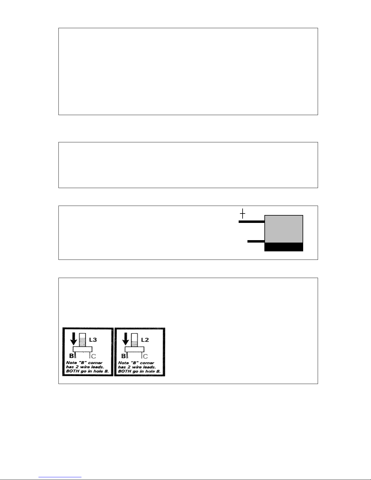
Table 1-E
CERAMIC DISC CAPACITORS
The vast majority of capacitors in this circuit are the ceramic disc type. Our
protocol is to identify those in picofarads up to 99 pF simply as 1 pF or 33 pF, etc.
There may be one letter to identify temperature characteristics (e.g. 33J = 33 pF.)
)URPS)PDUNHGRQXSWRFDSDFLWRUVLQWKHȝ)UDQJHZHSURYLGHWKH
exact part marking (101, 102, 103, 151, 181, etc.) minus any letter. All disc
capacitors are specified to fit the exact lead spacing on the board: if a
capacitor seems too big or too little for the spacing, you have selected the
wrong part!
Table 1-F
MYLAR FILM CAPACITORS
These capacitors have shiny, thick, rectangular bodies with value markings just
like on the ceramic disc capacitors. In this kit design, the mylar film parts (used in
the PLL filter and RF bandpass filter) have values different from any of the disc
capacitors, with the sole exception of C11,ȝ)
Table 1-G
ELECTROLYTIC CAPACITORS
These cylinder shaped parts are easy to recognize
from their longer (+) leads and clearly marked wide
negative band. In this kit, just be sure to identify an
LQVWDOOFRUUHFWO\WKRVHVPDOOHVWȝ)DQGȝ)
capacitors as specified in the directions.
Table 1-H
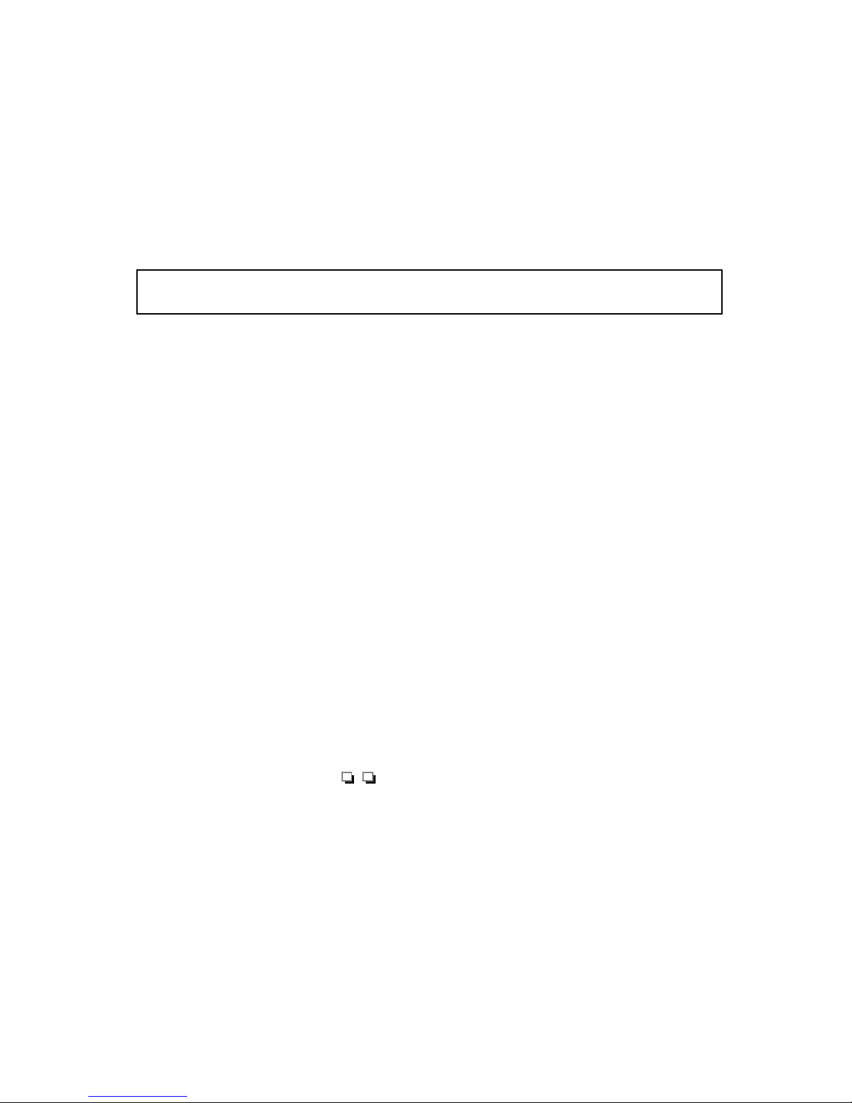
³63(&,$/´3$576
³6SHFLDO´SDUWVLQFOXGHFU\VWDOVILOWHUVEDOXQWUDQVIRUPHUVZKLFKDUHLGHQWLILHG
clearly by a manufacturer's number on the part itself OR by detailed description in
a kit assembly step. We give you plenty of help in the assembly instructions for
identifying and installing these parts correctly.
The VCO coils (Phase 3.0) are wound
on WHITE forms easily identified:
L3 (VCO-1): BROWN paint dot
L2 (VCO-2): RED paint dot
1254 ±Getting Started ±17

If you've never built an electronics kit before, you are a GOOD
candidate for successful construction of this receiver - because
we think you'll rely on this instruction manual very diligently.
("Experienced" builders tend to be more inclined to shortcuts
which can lead to mistakes!)
Both this manual and the engineering discipline for this receiver
were done with YOU very much in mind. We won't insult you
by claiming that "anybody" can build this receiver: you'll
certainly need the knowledge and skills you gained by working
for your ham license or studying electronics theory, and you'll
want to allow for a little more assembly time than may he
needed by those with more building experience"
Aside from the willingness to follow the directions in this manual,
the main skill you need is that of soldering. Here, it's a very
good idea to get some practice before working on the receiver
circuit boards. Building some simpler T-KlT projects is, of
course, a great way to get into kit building. Another way is to
take a circuit board from any discarded radio or other electronics
device and then remove a number of parts by melting their solder
connections. Re-install some or all of the parts, doing so until
your solder connections look as clean and professional as the
factory work. Don't hesitate to ask an electronics repair
technician to critique your work or show you a few tips.
Kit-Building Tips . . .
1 . Please USE the bits of knowledge and wisdom capsulized on
the back cover of your T-KIT Instruction Manual! You'll find
resistor color-codes, soldering tips and more!
2. Unfamiliar Words: We try to use plain language throughout
this manual, but electronics does have its special terms and
abbreviations. A "glossary" useful to this receiver project is
printed in the REFERENCE SECTION (Part 3) of this manual.
1254 ±Getting Started ±18
G. Building Electronic Kit Projects:
THE ESSENTIALS
3. SOLDERING: If you are inexperienced, ask any electronics
technician to show you how it's done, then do practice
soldering/de-soldering on a junked circuit board before working
on your kit. Here's what is important:
9Keep the soldering iron tip CLEAN, using a damp sponge
9Let the heated connection itself melt the solder, not the iron tip
9Use a thin diameter of rosin-core solder
9Use VERY good lighting; NEVER be embarrassed to use a
magnifier!
4. DE-SOLDERING is the opposite of soldering and is a more
tedious procedure. Again, a repair technician can show you the
best technique. Take care not to damage circuit board pads or
traces - save yourself from desoldering agony by installing the
right part the right way the first time!
5. Except for P1 , P2 and J5 mounted on the bottom ("solder
side") of the board, ALL Main Board parts are inserted into the
top silkscreened side, with leads passing through the holes to the
bottom solder side. (This advice may seem insulting, but some
folks DO carefully mount and solder all parts on the copper side
of the board and wonder why the kit won't work!)
6. Insert all parts as close to the board surface as possible before
soldering and trimming. Excess wire length above the board can
cause unwanted oscillations.
7. Reminder about your Kit Manual: NEVER "Solder first and ask
questions later" ! The Success of your project depends on your
willingness to study our published directions attentively. Check
your kit package for any update sheet(s) to supplement this
manual. Use the double check blocks to review your work
(ideally with someone else) before connecting voltage.
8. TOOLS: Page 14 lists the "minimum" tools needed for this
particular project. However, you'll appreciate owning a more
varied collection of small tools for electronics work: the selection
at Radio Shack'" is good, with the lower-priced versions being
quite sufficient. If buying your first voltmeter ("multitester"), you
may find the "analog" meter type easier to use at first than the
digital type.
1254 ±Getting Started - 19
WORTH REPEATING
Let the heated connection itself melt the solder, NOT the iron tip!
Table of contents
Other Ten-Tec Receiver manuals


