Ten-Tec 229 User manual

TEN-TEC
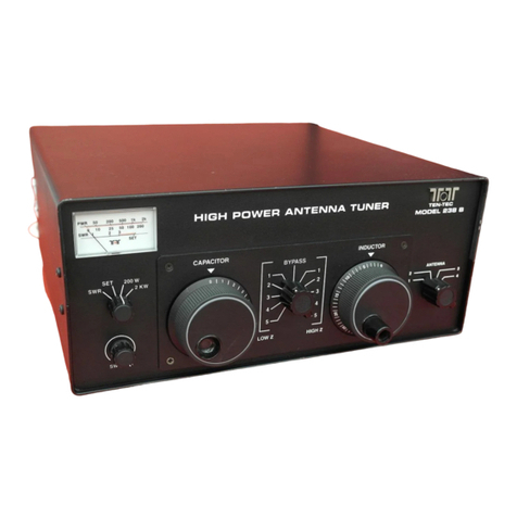
MODEL 229 ANTENNA TUNER
OWNER'S MANUAL
Part # 74123


GENERAL
The m del 229 antenna matching unit is an adjustable reactive netw rk used f r matching the
unbalanced 50 hm utput impedance f transmitters and transceivers t a variety f l ads, either
balanced r unbalanced. It will perf rm this functi n ver a frequency range f 1.8 t 30 Mhz.
Pr visi n is made f r selecting ne f f ur antennas r f r bypassing the matching netw rk. A dual
range p wer and SWR meter is included.
SPECIFICATIONS
Circuit: M dified "L" netw rk.
RF P wer: 2KW.
Frequency Range: 1.8 t 30 Mhz.
Output Matching Range: At least 10:1 SWR, any phase angle, 1.8 t 30 Mhz. 3,000 hms
maximum at full p wer.
Maximum Balanced L ad (thr ugh the balun): 500 hms.
Input Impedance: 50 hms, n minal.
Capacit r V ltage Rating: 3.5KV.
Induct r: 18 uh silver plated r ller induct r.
Finish: Dark painted fr nt and rear, textured sides and t p.
Size: HWD 5-1/2" x 13" x 11", verall.
Weight: 9 lbs.
INSTALLATION
1. C nnect c axial utput f transmitter t c axial input f tuner with sh rt length f
RG-8 r RG-58 cable. C nnect rs are PL-259 type. N tice: T reduce p ssibility f RF
getting int transmitter, p siti n tuner as far away fr m transmitter as is practical
especially when using pen wire feedlines r l ng wire antenna.
2. C nnect stati n gr und buss t terminal n tuner marked GND with heavy metallic
braid r wire. This lead sh uld g t the earth gr und system with as sh rt a lead as
p ssible.
3. C nnect antenna transmissi n line(s) t appr priate terminals n the tuner as f ll ws:
A. F r c ax fed antennas (unbalanced transmissi n lines), use either ANT 1,
ANT 2, ANT 3, r ANT 4.
B. F r single wire antenna, c nnect t SINGLE WIRE terminal.
C. F r balanced feedline systems, first install a jumper fr m SINGLE WIRE t ne
BALANCED LINE terminal with a sh rt wire. Then, c nnect feedline t the tw
BALANCED LINE terminals.
In b th single wire and balanced line systems, take special care t r ute transmissi n line
as far away fr m stati n equipment as p ssible. Never drape lines ver transmitter.
These lines may have high v ltage p ints inside the shack which present high rf fields.

D. ANT 4 p siti n can be c ax, single wire r balanced. ANT 1, 2, r 3 c ax nly.
4. The SWR bridge p wer meter is in the circuit at all times, even in BYPASS p siti n.
5. Apply +11 t 13.5 V dc f r the panel lights.
OPERATION
MATCHING
1. Always use the minimum transmitter p wer necessary t perate the SWR/POWER meter. T
d this, set the meter switches t REV and SWR and turn the SWR SET t full CW p siti n.
2. Set the CAPACITOR t 2, the INDUCTOR t full scale, and S1 t 50 hms BYPASS.
3. Apply en ugh transmitter drive t btain a half-scale meter reading.
4. Switch t either side f the BYPASS p siti n t determine which results in a l wer meter
reading and leave it there.
5. Alternately adjust the CAPACITOR and INDUCTOR f r l west meter reading.
6. If the CAPACITOR sh ws best meter null at 0, turn S1 t ther side f 50 hms BYPASS.
7. If the best meter null is with the CAPACITOR at 10, turn S1 t the next higher p siti n.
8. Once a null reached, t determine is sufficiently l w, set the meter switches t FWD and SWR
and adjust the SWR SET c ntr l t the full scale SET mark. Switch back t REV and read the
SWR n the l wer meter scale. A reading less than 1.5 is usually acceptable.
9. It is c nvenient t rec rd the c ntr l settings f r each antenna and band. Tune-up n a given
band will be simplified by having the settings already established.
ANTENNA SELECTION
A maximum f f ur antennas may be c nnected t the m del 229 at ne time, nly ne f which
may be a wire fed antenna. Whether the antenna selected is matched r fed directly is determined by
the setting f S1. The 50 hm BYPASS p siti n bypasses nly the mathcing netw rk, leaving the
SWR/POWER meter in line.
Antenna p siti n 4 feeds ANT 4, SINGLE WIRE r, with jumper installed, BALLANCED LINE. Only
ne antenna, c ax, single line r balanced line feed, may be attached at ne time t these utputs;
therwise the antennas will be fed in parallel and the l west impedance antenna will receive the m st
p wer. When using either ANT 4 (c ax) r the SINGLE WIRE terminal, d n t c nnect the jumper
between SINGLE WIRE and ne BALANCED LINE terminal as damage t the balun may result.

POWER - SWR METER
The meter circuit all ws measurement f the f rward and reverse p wer in tw ranges, 0 - 200 W
and 0 - 2 KW. Measuring SWR is c vered in step 8 ab ve.
CAUTIONS
1. In the n rmal perati n f the M del 229 matching unit very high RF v ltages and currents
can ccur at s me p ints in the circuit. Be very careful if the tuner is ever used while the
c ver is rem ved.
2. While all the c m nents are rated t easily handle c ntinu us perati n at maximum p wer,
certain l ads will pr duce currents which exceed the "h t switching" capabilities f the
ceramic wafer switches. Theref re, never change the p siti n f either switch with high rf
p wer applied. H wever, up t 100 W rf may be h t switched n S1 during the initial tune up
pr cedure. Failure t bserve this warning may result in permanent damage t the c ntacts
f the wafer switches.
3. Always be sure that a dummy l ad r antenna is pr perly c nnected when p wer is applied.
V ltages in excess f ratings can ccur if n l ad is c nnected.
SEVERAL OPERATING HINTS
If it is n ticed that placing y ur hand n the t p f the tuner causes a shift in SWR, it is an
indicati n f excessive "rf in the shack." Impr ve the gr und system r change the length f the
feedline slightly. This is especially n ticeable when using wire-fed antennas.
When using BALANCED LINE, if the SWR rises during a l ng transmissi n, it is an indicati n that a
significant p rti n f the transmitter p wer is being l st in the balun. This will be the case when the
antenna impedance is greater than 500 hms. Changing the length f the antenna and/ r feedline
will usually cure this pr blem.

Figure 1
CIRCUIT DESCRIPTION
The matching circuit used in the m del 229 is basically an "L" netw rk. The "L" netw rk has
several advantages ver ther circuit c nfiguati ns. It has nly tw adjustable parts, ne induct r
and ne capacit r; m st ther netw rks use three. Because there are n internal n des in the
netw rk, the maximum circuit v ltages and currents which ccur are never are never m re than th se
present at the input r utput terminals. Because there are nly tw variable c mp nents, there is
nly ne setting f each which will pr vide a perfect match t a given l ad impedance, and this
unique setting aut matically pr vides the l west netw rk Q p ssible. L w Q means l w circulating
currents, hence l w l ss, and it als pr vides the widest frequency bandwidth f perati n bef re
retuning is necessary. Finally, since the induct r is always parallel, the netw rk always pr vides a
tw -p le l wpass resp nse t pr vide harm nic rejecti n.
There are, h wever, s me disadvantages which have prevented wider use f the "L" netw rk in
the past. First, t match all p ssible antenna l ads, tw c nfigurati ns are required. One, f r
impedance greater than 50 hms, requires the capacit r t be acr ss the antenna. The ther requires
the capacit r t be acr ss the transmitter when the antenna impedance is less than 50 hms. This
functi n is perf rmed by switch S1. At high frequencies, as the l ad impedance appr aches 50 hms,
i.e. the antenna has a fairly l w SWR already, the values f L and C in the netw rk required f r a
perfect match bec me very small -- smaller than the stray r minimum values f the c mp nents
used. T circumvent this pr blem, a small fixed c mpensating capacit r r induct r is placed int the
circuit depending n whether the netw rk is c nfigured f r high r l w impedance respectively (HI r
LOW n switch S1). At l w frequencies, the value f netw rk capacity needed t match s me l ads is

quite large, requiring a large and expensive capacit r. T pr vide f r this, fixed capacit rs are placed
in parallel with the variable capacit r t btain the value needed. This functi n is als pr vided by
switch S1; further r tati n fr m the center p siti n increases the value f capacitance in the circuit.
(see circuits illustrated in Figure 2 at the end f this manual)
ANTENNA SYSTEMS MATCHING THEORY
M st transmitters are designed t w rk int a 50 hm resistive l ad, and they are n t able t
effectively supply rf p wer t l ads that depart far fr m this value. H wever, many antenna systems,
which include the antenna and transmissi n line, have c mplex impedance that make it difficult if n t
imp ssible t l ad the transmitter pr perly. These impedances are a functi n f the perating
frequency, type f antenna, type and length f transmissi n line, height f antenna and pr ximity t
ther bjects.
The M del 229 pr vides a c upling meth d t c nvert the resistive/reactive l ad t a pure
resistance f 50 hms that will accept maximum p wer fr m the transmitter. This is n t t say that
any and all antennas, when c nverted t a 50 hm resistance impedance by means f a tuner, will
give identical perf rmance. T best understand the tuner adjustments required, it is necessary t
have a fundamental kn wledge f h w antenna systems functi n. T this end, a sh rt technical
discussi n f ll ws. It is rec mmended that additi nal reading n the subject be d ne by th se
interested in btaining maximum perf rmance fr m their antenna systems. The ARRL Antenna
Handb k, ARRL Amateur's Radi Handb k (antenna and transmissi n line secti ns) and ther
antenna b ks published by the publishers f Amateur Radi magazines are excellent s urces f
inf rmati n.
THE ANTENNA - Any c nduct r that has rf currents fl wing in it can be l ked n as an antenna r
radiat r. The extent t which p wer leaves the c nduct r and radiates int the surr unding medium
depends n many fact rs -- length, frequency, am unt f current, c nfigurati n, etc. Since the
antenna abs rbs p wer fr m the device feeding it, it can be replaced with a resistance wh se value is
such that the p wer delivered t this resistance is n w a measure f the radiating effectiveness f the
antenna and is termed "radiati n resistance." F r a given value f antenna current, the higher this
resistance, the m re p wer that is radiated. (P=I
2
R)
Due t the facts that an antenna has physical length, that currents travel at a vel city less than
instantane us and that the c nduct r p sses a certain am unt f self-inductance and capacitance, the
current at the feedp int may n t be in phase with the v ltage at this p int. As a result, the
impedance at this p int may n t l k like the pure resistance suspected, but as an impedance
c nsisting f resistance and either inductive r capacitive reactance. This added reactance will limit
the am unt f current supplied t the antenna f r a given v ltage, and theref re reduce the am unt
f radiated p wer. The reactance d es n t abs rb p wer in itself -- nly a resistance can d that --
but its presence reduces the verall radiated p wer and antenna current.
There are tw ways t rest re the p wer t its n n-reactive value. The first, which is n t the
preferred way because it d es n t maximize p wer transfer, is t raise the feedp int v ltage s that
the current returns t its riginal value. The sec nd, and preferred meth d, is t add a reactance in
series , equal in value but pp site in type (sign) t the reactance value f the antenna. F r example,
if the antenna at the perating frequency presents an inductive reactance f 100 hms (+j100) al ng
with a resistance f 50 hms, inserting capacit r wh se reactance is als 100 hms (-j100) in series

has the effect f cancelling ut the reactance f the antenna, leaving nly the 50 hms resistive. This
can be l ked n as a series R,L,C circuit that is in res nance, wh se t tal impedance is nly that f
the resistance. An ther term f r this appr ach t maximize p wer transfer is "c njugate impedance
matching."
In the ab ve example, we used a value f 50 f r the radiati n resistance. If this value were n t 50
but 150 hms, the impedance after cancelling the reactance ut w uld be 150 hms. C nnecting this
l ad t the transmitter designed t perate with 50 hms l ad w uld n t result in ptimum p wer
transfer. It w uld, h wever, be better than leaving the inductive reactance in, since the antenna
current is maximized f r the c nditi ns that d exist. T btain design perf rmance, it is necessary t
transf rm the 150 hms t 50. This can be d ne with a transf rmer with a turns rati f 1.73 t 1.
(Impedance transf rmati n is equal t the square f the turns rati .) It is als p ssible t acc mplish
this transf rmati n with a parallel tuned circuit with primary and sec ndary taps pr perly l cated n
the induct r, r using tw r m re capacit rs in series with taps taken fr m the series string. Under
these c nditi ns, the transceiver will deliver rated p wer t the antenna.
One last bservati n bef re we g n. The antenna impedance in the ab ve example as that at
the feedp int. If we n w feed the antenna at a different l cati n al ng the c nduct r, the impedance
will be different, b th resistive and reactive c mp nents. There are an infinite number f impedance
ch ices available, depending n where the tap is made. This fact r is helpful in designing and
matching antennas. The fact rs that determine this impedance are the current and v ltage values at
this p int, and the phase between them.
THE TRANSMISSION LINE - In the ab ve example, we assumed that the transmitter utput was
c nnected directly t the feed p int. This is hardly practical. S that the transmitter can be l cated at
a distance fr m the antenna, we use a transmissi n line t deliver the p wer. Unless we have a
perfectly matched system, i.e. antenna, line and transmitter utput impedances all the same value
with ut reactive c mp nents, the additi n f the transmissi n line c mpletely changes the picture.
The transmitter will n t see the antenna impedance f 50 hms resistive and 100 hms inductive
reactance, but s me ther c mbinati n. It will depend n the electrical length f the line, its
characteristic impedance and frequency. The impedance at the transmitter end is what we are
interested in, and the inductive c mp nent may even be changed t capacitance. (Only when the
electrical length f the line is an exact multiple f the half wavelength will the impedance at the
transmitter be the same as the antenna impedance.)
Briefly, the line characteristic impedance is determined by the physical dimensi ns f the line -
wire diameter and spacing - and the dielectric f the material in between. The wire als p ssesses a
resistive c mp nent which will dissipate p wer when current fl ws thr ugh it t the antenna. This
sh ws up as heat l ss and dictates use f l w l ss cable. F rmulas f r c ax and pen wire line
impedances are given in the handb ks.
Since rf currents fl w in the transmissi n line, ne may ask if it then bec mes an antenna. In the
case f c ax type lines, the current sh uld fl w n the inside surface f the uter c nduct r and uter
surface f the inner c nduct r. The electric and magnetic fields caused by the current fl w are
c nfined between the tw , s n ne can escape and be radiated. If a system c nfigurati n results in
s me rf current fl wing n the uter surface f the uter c nduct r, such as when a dip le is fed with
c ax with ut a balun r ther means f changing the feed line fr m an unbalanced t balanced
c nfigurati n, it will radiate p wer. In the case f parallel lines, the current in ne c nduct r at a

given l cati n sh uld be fl wing in the pp site directi n t the current in the adjacent c nduct r,
and if the system is well balanced, the amplitudes f the tw will be equal. Under these c nditi ns,
the tw sets f fields exactly cancel each ther and very little radiati n will result. If the tw currents
are n t equal r n t in exact pp site phase, there will be radiati n. Als , if the spacing between
lines is a c nsiderable p rti n f the wavelength, radiati n will ccur. This is n t a fact r bel w VHF.
One final characteristic f transmissi n lines sh uld be menti ned. The rf current fl wing in the
line travels at a speed less than that f radiated p wer in a vacuum, r the speed f light, b th
186,000 miles per sec nd. This sl wing is caused by the dielectric pr perty f the medium thr ugh
which the field traverses. In c ax cables it is p lyethelene between inner and uter c nduct rs, and
in parallel lines, it may be the plastic between the c nduct rs, in the case f twin-lead type line, r the
air and plastic spacers in pen wire types. The rati f the speed in the line t the speed in a vacuum
(air is alm st the same) is called the vel city fact r f the cable. It is always less than unity. Because
f this sl wing, the physical length f a transmissi n line is n t the same as the electrical length. F r
example, the wavelength in free space f a 30 MHz signal is exactly 10 meters. A transmissi n line 10
meters l ng will be ne full wavelength nly if the dielectric between the c nduct rs is air. In the
case f c ax cable with p lyethelene dielectric, the vel city fact r runs ab ut 0.67. The same 10
meter length f cable will n w appear electrically as an pen wire r air dielectric cable 15 meters
l ng (10 divided by 0.67). This is equivalent t ne and ne half wavelengths. A p lyethelene
type cable w uld nly have t be 6.7 meters l ng t be ne wavelength.
EFFECT OF TRANSMISSION LINE ON ANTENNA IMPEDANCE - As a result f all f the ab ve, in
situati ns where we d n t have a matched system thr ugh ut, and this is m st f the time, the
impedance presented t the transmissi n line by the antenna sets up standing waves n the line.
These standing waves will alter the antenna impedance all al ng the line t ward the transmitter.
What we really want t acc mplish with the antenna tuner is t take whatever impedance that is
established at the transmitter end f the line and alter it t a 50 hm resistance. Then the transmitter
will be happy, at least. The tuner will n t affect the mismatch f antenna t line - nly c nstructing
the antenna differently will d that - n r eliminate a standing wave n the transmissi n line. It will
eliminate a standing wave n the line between transmitter and tuner input, but n t n the utput
side f the tuner. A g d antenna is still needed t "get ut." If the antenna has a l w resistance, the
tuner will transf rm it, al ng with the cable l ss resistance, t 50 hms. The full p wer will enter the
system, but it will be divided between radiati n and cable heat l ss. It is n t unc mm n that m re
than half f the available p wer is wasted in cable l sses, even with l w l ss cable. It just gets a bit
h tter. The split depends entirely n the rati f radiati n resistance t l ss resistance.
What is the impedance established at the transmitter end f the line? It depends first n the
antenna impedance, which is then transf rmed by the line. This transf rmati n is dependent n
frequency, electrical length f the line and the l ss in the line. In an Amateur setup where many
different frequencies are used with the same antenna, there will be a multitude f impedances
presented t the tuner, s adjustment f the matching netw rk will be required as frequency is
changed.
STANDING WAVE RATIO - A measure f h w badly a system is mismatched is given by the
standing wave rati (SWR) n the line. SWR is the rati f the maximum v ltage enc untered al ng a
transmissi n line greater than ne half wave-length l ng t the minimum v ltage. It is als the rati
f maximum t minimum current. The m re nearly unif rm the v ltage distributi n al ng the line,
the cl ser matched it is, and the ultimate is when the v ltage is c nstant d wn the length f a l ssless

line, r dr ps sl wly and unif rmly al ng a line with l sses. This is the matched c nditi n,
represented by a 1 t 1 SWR. The impedance at the l ad end f such a line is the same as that at the
generat r end. When adjusting a matching netw rk pr perly, the way t d it is t bserve the
SWR and tune f r as l w a rati as p ssible.
The SWR is als an indicati n f the value f resistance at the l ad end. The rati is the same as
the rati f l ad resistance t line characteristic impedance. This rati can mean that the l ad is
either greater than r less than the line's impedance. F r example, if the SWR n a length f 50 hm
line is 3 t 1, the l ad resistance is either 150 hms r 16.7 hms (3 times 50 r ne-third f 50). This
is nly accurate with pure resistive l ads.
It can be sh wn mathematically that a 2 t 1 SWR in a system which has the transmitter utput
impedance equal t the line impedance delivers 89% f the measured f rward p wer t the l ad.
This relates t a p wer l ss f half a decibel - hardly n ticeable in signal strength. At a 3 t 1 rati , the
l ss bec mes appreciable with 75% f the measured f rward p wer delivered. S in adjusting
antenna tuners, it is a nice feeling if y u achieve a 1 t 1 match, but in reality, anything bel w 2 t 1 is
satisfact ry. Line l sses d increase a bit als with increasing SWR, but it is still a small fracti n f a
dB at 2:1.
OVERALL SUMMARY
1. Any antenna can be represented as an equivalent resistive/reactive impedance wh se
resistive c mp nent, termed radiati n resistance, is a measure f the p wer radiated.
Reactance can be either inductive r capacitive.
2. Antenna impedance is a functi n f frequency, c nfigurati n, selecti n f feed p int l cati n,
height ab ve gr und and nearness t surr unding bjects.
3. The reactive p rti n f the impedance d es n t abs rb p wer but limits the am unt f p wer
radiated by the resistive c mp nent. It is best t eliminate the reactive c mp nent, by
inserting an equal value reactance in series, but f the pp site type.
4. Best system perf rmance is attained when antenna impedance is purely resistive with value
equal t transmissi n line impedance, which in turn equals transmitter utput impedance.
5. Since antennas seld m present matched impedances t line ver a band f frequencies and
fr m band t band, a partial s luti n t using these mismatched systems is t c nvert the
impedances at the transmitter end f the line t what the transmitter is designed f r, with an
antenna tuner.
6. The transmissi n line will change the antenna impedance in b th resistive and reactive values
at the transmitter end, depending n the line's electrical length, frequency and characteristic
impedance.
7. Due t sl wing d wn f the current fl w in the transmissi n line fr m that in free space, the
electrical length f a line will be l nger than the physical length.

8. One special situati n where the line d es n t alter the impedance is when its length is an
exact multiple f the electrical half wavelength.
9. An antenna tuner will n t affect the antenna impedance n r the standing wave c nditi n n
the transmissi n line. It will c rrect the SWR n that p rti n f the line between transmitter
utput and tuner input, s that the transmitter will supply rated p wer t the system.
10. Standing wave rati , SWR, is a measure f the mis-match f the system and is used as the
indicat r when making tuner adjustments. SWR is direct rati f l ad resistance t line's
characteristic impedance.
11. SWR ther than 1 t 1 indicates tw p ssible impedances, ne greater and ne less than
characteristic impedance.
12. Any SWR value less than 2 t 1 is c nsidered a g d match.
ALIGNMENT
SWR BRIDGE
In the unlikely event SWR bridge adjustment bec mes necessary, pr ceed as f ll ws:
1. C nnect a 50 hm dummy l ad t any antenna jack.
2. Turn the ANTENNA switch t the same antenna p siti n and S1 t 50 hm BYPASS.
3. Set the meter switches t 200 W, SWR and REV.
4. Turn the SWR SET t full CW.
5. Apply p wer fr m the transmitter n 14 MHz and adjust the trimmer, C27 in the SWR bridge
f r a null.
WATT METER CALIBRATION
1. Place S1 in the 50 hm BYPASS p siti n and c nnect a dummy l ad t the utput.
2. C nnect the transmitter thr ugh a calibrated wattmeter t the input.
3. Set the meter switches t FWD, 200 W, and POWER.
4. Apply 50 t 100 watts fr m the transmitter and adjust R28 (right hand p t) t agree with the
external wattmeter.
5. Set the meter switch t the 2 kW range.
6. Apply 500 t 1000 watts fr m the transmitter and adjust R30 (left hand p t) t agree with the
external wattmeter.

PILOT LAMP REPLACEMENT
The meter and dial scale lamps are all 14 v lt, bay net type, N . 1813 r 1892. Access t these
bulbs is by rem ving the t p f the unit.
DIAL STRING REPLACEMENT
The dial string mechanism c nsists f tw parts - a .020" diameter dacr n n n-stretchable string
and an elastic c rd. The diameter f the dacr n is imp rtant f r pr per p inter read ut, since it is
w und n the induct r shaft and carries the p inter acr ss the scale. Replace nly with a string f the
same diameter. The elastic secti n pr vides string tensi n. B th are available fr m TEN-TEC. T
install, rem ve the t p c ver and unplug the meter plug fr m the switch b ard. Rem ve the kn bs
and then the fr nt panel. Tie a small l p in each end f the elastic c rd such that the distance
between l ps is 14". Similarly tie l ps in each end f the dial string such that the t tal length
between l ps is 46". Run the induct r t the full cw st p (r ller t the rear) pr perly. H k ne l p
f the string ver the left pulley shaft (n t the pulley itself) n the p inter and place the p inter n
the t p left edge f the subpanel. Run the string fr m the p inter ver the left fr nt pulley, back ver
the pulley n the p inter, back ver the left rear pulley, d wn the left edge f subpanel ar und the
c rner stand ff and finally under and ar und the induct r shaft where the end l p h ks ver the
r ll pin in the shaft. H k ne f the elastic l p ends ver the l wer left subpanel stand ff, and run
the c rd acr ss the b tt m edge, ar und the l wer right stand ff, ver the t p right pulley and h k
the l p end ver the right hand pin n the p inter. This will n w have the p inter tensi ned.
Replace the fr nt panel and induct r kn b and turn the induct r t the full CCW st p. While h lding
the induct r kn bs, l sen the fr nt set screw n the fr nt induct r shaft c upler and turn the kn b
until the p inter lines up with the zer n the dial scale then tighten the setscrew. Run the induct r
thr ugh its full range t see that the p inter has free travel and return t the zer p int. L sen the
induct r kn b setscrew and p siti n the zer mark n the kn b skirt at t p center and tighten the
setscrew. Replace the remaining kn b making sure that 10 n the capacit r kn b skirt c insides with
full mesh p siti n f the capacit r.
160 METER NOTE:
S me l w impedances n 160 meters may require m re capacitance than the 2400 pf available
with the capacit r at full mesh and S1 at p siti n 5 n the LOW B side. Under such a c nditi n, adding
an additi nal 1000 pf (.001 uf) 1 KV capacit r acr ss the variable will usually pr duce a perfect match.
A l w l ss ceramic r mica transmitting capacit r sh uld be used. If ne cann t be btained l cally,
TEN-TEC will gladly supply ne at n charge.

TUNER CONFIGURATIONS -- Selected by S1
Figure 2


Table of contents
Other Ten-Tec Tuner manuals


