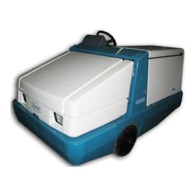
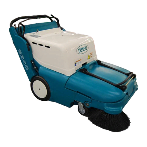
Tennant 6400E User manual

MM434
Rev. 02 (11--01)
Service Manual
6400E

This service manual is intended to be used as an aid in the detailed service, repair, and troubleshooting of
your TENNANT Model 6400E.
The set is organized into five major groups: General Information, Chassis, Sweeping,
Electrical, and Hydraulics.
General Information: Safety precautions, machine specifications, machine maintenance chart, machine
tieing, machine jacking, machine storing, machine pushing or towing, and hardware information.
Chassis: Tire/wheel replacement, brake adjustment and replacement, seat removal and installation,
chassis lubrication, and steering adjustment and replacement.
Sweeping: Hopper repair/replacement, brush repair/replacement, skirt/seal repair/replacement, and
sweeping troubleshooting.
Electrical: Battery maintenance and replacement, instrument panel replacement, and electrical
troubleshooting.
Hydraulics: Valve replacement/repair, motor replacement/repair, cylinder replacement/repair, pump
replacement/repair, filter replacement, and hydraulics troubleshooting.
Manual Number -- MM434
Revision: 02
Published: 11--01
Copyright E1999, 2001 TENNANT, Printed in U.S.A.

GENERAL INFORMATION
1-1
6400E MM434 (11--01)
CONTENTS
Page
SAFETY PRECAUTIONS 1--3................
SPECIFICATIONS 1--5......................
GENERAL MACHINE
DIMENSIONS/CAPACITIES
GENERAL MACHINE PERFORMANCE 1--5.
POWER TYPE 1--6.......................
STEERING 1--6..........................
HYDRAULIC SYSTEM 1--6................
BRAKING SYSTEM 1--6..................
TIRES 1--6..............................
MACHINE DIMENSIONS 1--7..............
MAINTENANCE 1--8........................
MAINTENANCE CHART 1--8..............
PUSHING, TOWING, AND TRANSPORTING
THE MACHINE 1--10...................
PUSHING OR TOWING THE
MACHINE 1--10....................
TRANSPORTING THE MACHINE 1--10..
MACHINE JACKING 1--12.................
STORING MACHINE 1--12................
HARDWARE INFORMATION 1--13............
STANDARD BOLT TORQUE CHART 1--13..
METRIC BOLT TORQUE CHART 1--13.....
BOLT IDENTIFICATION 1--13..............
THREAD SEALANT AND LOCKING
COMPOUNDS 1--13...................
HYDRAULIC FITTING INFORMATION 1--14....
HYDRAULIC TAPERED PIPE FITTING
(NPT) TORQUE CHART 1--14..........
HYDRAULIC TAPERED SEAT FITTING
(JIC) TORQUE CHART 1--14...........
HYDRAULIC O--RING FITTING
TORQUE CHART 1--14................
MACHINE TROUBLESHOOTING 1--15.....

GENERAL INFORMATION
1-2 6400E MM434 (11--01)

GENERAL INFORMATION
1-3
6400E MM434 (11--01)
SAFETY PRECAUTIONS
The following symbols are used throughout this
manual as indicated in their description:
WARNING: To warn of hazards or
unsafe practices that could result in
severe personal injury or death.
FOR SAFETY: To identify actions that
must be followed for safe operation of
equipment.
The following information signals potentially
dangerous conditions to the operator or
equipment. Read this manual carefully. Know
when these conditions can exist. Locate all safety
devices on the machine. Then, take necessary
steps to train machine operating personnel.
Report machine damage or faulty operation
immediately. Do not use the machine if it is not in
proper operating condition.
FOR SAFETY:
1. Do not operate machine:
-- Unless trained and authorized.
-- Unless operation manual is read and
understood.
-- In flammable or explosive areas unless
designed for use in those areas.
-- In areas with possible falling objects
unless equipped with overhead guard.
2. Before starting machine:
-- Make sure all safety devices are in
place and operate properly.
-- Check brakes and steering for proper
operation.
3. When starting machine:
-- Keep foot on brake and directional
pedal in neutral.
4. When using machine:
-- Use brakes to stop machine.
-- Go slowly on inclines and slippery
surfaces.
-- Use care when reversing machine.
-- Move machine with care if hopper is
raised.
-- Make sure adequate clearance is
available before raising hopper.
-- Do not carry riders on machine.
-- Always follow safety and traffic rules.
-- Report machine damage or faulty
operation immediately.
5. Before leaving or servicing machine:
-- Stop on level surface.
-- Set parking brake.
-- Turn off machine and remove key.
6. When servicing machine:
-- Avoid moving parts. Do not wear loose
jackets, shirts, or sleeves when
working on machine.
-- Block machine tires before jacking up
machine.
-- Jack up machine at designated
locations only. Block machine up with
jack stands.
-- Use hoist or jack that will support the
weight of the machine.
-- Wear eye and ear protection if using
pressurized air or water.
-- Disconnect battery connections before
working on machine.
-- Avoid contact with battery acid.
-- Use cardboard to locate leaking
hydraulic fluid under pressure.
-- Use Tennant supplied or equivalent
replacement parts.
7. When loading/unloading machine
onto/off truck or trailer:
-- Turn off machine.
-- Use truck or trailer that will support
the weight of the machine.
-- Use winch. Do not drive the machine
onto/off the truck or trailer unless the
load height is 380 mm (15 in) or less
from the ground.
-- Set parking brake after machine is
loaded.
-- Block machine tires.
-- Tie machine down to truck or trailer.
WARNING: Batteries emit hydrogen gas.
Explosion or fire can result. Keep
sparks and open flame away. Keep
covers open when charging.
WARNING: Lift arm pinch point. Stay
clear of hopper lift arms.
WARNING: Raised hopper may fall.
Engage hopper support bar.
WARNING: Moving belt and fan. Keep
away.
GENERAL INFORMATION
1-4 6400E MM434 (7--99)
The following safety labels are mounted on the
machine in the locations indicated. If these or any
labels become damaged or illegible, install a new
label in its place.
BATTERY CHARGING LABEL -- LOCATED ON
THE CONTROL BOX.
FOR SAFETY LABEL -- LOCATED ON THE
SIDE OF THE OPERATOR COMPARTMENT.
HOPPER LIFT ARMS LABEL -- LOCATED ON
BOTH LIFT ARMS.
HOPPER SUPPORT LABEL -- LOCATED ON
BOTH LIFT ARMS AND THE HOPPER
SUPPORT BAR.
FAN AND BELT LABEL -- LOCATED ON THE
VACUUM FAN HOUSING AND BELT SHROUD.
350158

GENERAL INFORMATION
1-5
6400E MM434 (11--01)
SPECIFICATIONS
GENERAL MACHINE DIMENSIONS/CAPACITIES
Item Dimension/capacity
Length 2085 mm (82 in)
Length with side brush 2260 mm (89 in)
Width 1230 mm (48.4 in)
Width with side brush 1395 mm (55 in)
Height 1435 mm (56.5 in)
Height with overhead guard 2085 mm (82 in)
Track 1135 mm (44.7 in)
Wheelbase 1135 mm (44.7 in)
Main sweeping brush diameter 355 mm (14 in)
Main sweeping brush length 915 mm (36 in)
Side brush diameter 585 mm (23 in)
Sweeping path width 915 mm (36 in)
Sweeping path width with side brush 1270 mm (50 in)
Main sweeping brush pattern width 50 to 75 mm (2to3in)
Hopper weight capacity 315 kg (700 lb)
Hopper volume capacity 315 L (11.25 ft3)
Dust filter area 6.9 m2(74 ft2)
GVWR 2041 kg (4500 lb)
Ceiling height minimum dumping clearance 2340 mm (92 in)
GENERAL MACHINE PERFORMANCE
Item Measure
Maximum forward speed 8km/h (5 mph)
Maximum reverse speed 4.8 km/h (3 mph)
Minimum aisle turn width, left 2360 mm (93 in)
Minimum turning radius, right 1490 mm (58.7 in)
Minimum turning radius, left 1135 mm (44.7 in)
Maximum rated incline with empty hopper 10_/ 17.6%
Maximum rated incline with full hopper 8_/ 14.1%

GENERAL INFORMATION
1-6 6400E MM434 (7--99)
POWER TYPE
Type Quantity Volts Ah Rating Weight
Batteries 66315 @ hr rate 58 kg (127 lb)
218 340 @ hr rate 254 kg (560 lb)
218 440 @ hr rate 299 kg (660 lb)
Type Use VDC Kw (hp)
Electric Motors Propelling 36 1.6 (2.1)
Accessory 36 3(4)
Type VDC AHz Phase VAC
Chargers 36 50 60 1240
36 75 60 1variable
36 75 60 3variable
36 50 50 1230
36 75 50 3variable
36 45 50/60 1variable
STEERING
Type Power source Emergency steering
Rear wheel, hydraulic cylinder
and rotary valve controlled
Hydraulic accessory pump Manual
HYDRAULIC SYSTEM
System Capacity Fluid Type
Hydraulic reservoir 10.6 L (2.8 gal) TENNANT part no. 65870
Hydraulic total 12.1 L (3.2 gal)
p
Propelling gearbox 2.6L(2.7qt) SAE 90 Gear weight lubricant
BRAKING SYSTEM
Type Operation
Service brakes Mechanical drum brakes (2), one per front wheel, cable actuated
Parking brake Utilizes service brakes, cable actuated
TIRES
Location Type Size
Front (2) Solid 406x89x308(16x31/2x121/8)
Rear (1) Solid 406 x 102 x 308 (16 x 4 x 12 1/8)

GENERAL INFORMATION
1-7
6400E MM434 (11--01)
TOP VIEW
SIDE VIEW
930
mm
2085 mm
(82 in)
1230 mm
(48.4 in)
2260 mm
(89 in)
1135 mm
(44.7 in)
1135 mm
(44.7 in)
1395 mm
(55 in)
1435 mm
(56.5)
FRONT VIEW
2085 mm
(82 in)
350158 --- 350165
MACHINE DIMENSIONS

GENERAL INFORMATION
1-8 6400E MM434 (7--99)
MAINTENANCE
1
239
810 11 12
13
14
15
17
3
7
6
10
54
16 89
00000
MAINTENANCE CHART
Interval Key Description Procedure
Lubricant/
Fluid
No. of
Service
Points
Daily 8Brush compartment skirts Check for damage, wear, and
adjustment
-- 5
15 Hopper lip skirts Check for damage, wear, and
adjustment
-- 3
11 Main brush Check for damage or wear -- 1
Check brush pattern -- 1
13 Side brush Check for damage or wear -- 1
Check brush pattern -- 1
12 Hopper dust filter Shake -- 1
50 Hours 11 Main brush Rotate end-for-end -- 1
3Batteries Check electrolyte level DW 6(2)

GENERAL INFORMATION
1-9
6400E MM434 (7--99)
Interval Key Description Procedure
Lubricant/
Fluid
No. of
Service
Points
100 Hours 12 Hopper dust filter Check for damage, clean or
replace
-- 1
4Hydraulic fluid reservoir Check fluid level HYDO 1
9Tires Check for damage -- 3
1Propelling gearbox Check lubricant level -- 1
8Main brush and hopper
seals
Check for damage or wear -- 8
200 Hours 1Rear wheel support
bearings
Lubricate SPL 1
16 Brakes Check and adjust travel -- 1
2Steering link Lubricate SPL 1
10 Hopper lift arm pivots Lubricate SPL 2
14 Side brush pivot Check adjustment -- 1
14 Side brush guard Rotate 90_-- 1
5Vacuum fan belt Check tension and wear -- 1
5Hydraulic pump belt Check tension and wear -- 1
5Main brush intermediate
belt
Check tension and wear -- 1
5Main brush belt Check for wear -- 1
400 Hours 9Front wheel bearings Check for seal damage -- 2
800 Hours 4Hydraulic fluid reservoir Replace filler cap -- 1
y
Replace suction strainer -- 1
Change hydraulic fluid HYDO 1
6Hydraulic fluid filter Change filter element -- 1
-- Hydraulic hoses Check for wear and damage -- All
1Propelling gearbox HChange gear lubricant GL 1
p
g
g
HChange fill-level plug seals -- 1
1Rear wheel HTorque wheel nuts -- 1
1, 7 Electric motors Check carbon brushes -- 2
LUBRICANT/FLUID
DW Distilled water....
GL SAE 90 Gear lubricant....
HYDO Tennant or approved hydraulic fluid.
SPL Special lubricant, Lubriplate EMB grease (TENNANT part no. 01433--1)...
NOTE: Also check procedures indicated (H) after the first 50 hours of operation.
NOTE: More frequent intervals may be required in extremely dusty conditions.

GENERAL INFORMATION
1-10 6400E MM434 (11--01)
PUSHING, TOWING, AND TRANSPORTING
THE MACHINE
PUSHING OR TOWING THE MACHINE
If the machine becomes disabled, it can be
pushed from the front or rear, but tow it only from
the rear.
Only push or tow the machine for a very short
distance and do not exceed 3.2 kp/h (2 mph). It is
NOT intended to be pushed or towed for a long
distance or at a high speed.
ATTENTION! Do not push or tow
machine for a long distance or damage
may occur to the propelling system.
TRANSPORTING THE MACHINE
1. Position the rear of the machine at the
loading edge of the truck or trailer.
FOR SAFETY: Use truck or trailer that
will support the weight of the machine.
NOTE: Empty the hopper before transporting the
machine.
2. If the loading surface is not horizontal or is
higher than 380 mm (15 in) from the ground,
use a winch to load machine.
If the loading surface is horizontal AND is
380 mm (15 in) or less from the ground, the
machine may be driven onto the truck or
trailer.
3. To winch the machine onto the truck or
trailer, attach the winching chains to the rear
tie down locations. The rear tie-down
locations are the holes in the sides of the
machine frame near the rear bumper.
FOR SAFETY: When loading machine
onto truck or trailer, use winch. Do not
drive the machine onto the truck or
trailer unless the loading surface is
horizontal AND is 380 mm (15 in) or less
from the ground.

GENERAL INFORMATION
1-11
6400E MM434 (11--01)
4. Position the machine onto the truck or trailer
as far as possible. If the machine starts to
veer off the centerline of the truck or trailer,
stop and turn the steering wheel to center
the machine.
5. Set the parking brake and block the machine
tires. Tie down the machine to the truck or
trailer before transporting.
The front tie-down locations are the holes in
the wheel pockets at the front of the
machine frame.
The rear tie-down locations are the holes in
the sides of the machine frame near the rear
bumper.
6. If the loading surface is not horizontal or is
higher than 380 mm (15 in) from the ground,
use a winch to unload machine.
If the loading surface is horizontal AND is
380 mm (15 in) or less from the ground, the
machine may be driven off the truck or
trailer.
FOR SAFETY: When unloading machine
off truck or trailer, use winch. Do not
drive the machine off the truck or trailer
unless the loading surface is horizontal
AND 380 mm (15 in) or less from the
ground.

GENERAL INFORMATION
1-12 6400E MM434 (11--01)
MACHINE JACKING
Empty the hopper before jacking the machine.
You can jack up the machine for service at the
designated locations. Use a hoist or jack that will
support the weight of the machine. Always stop
the machine on a flat, level surface and block the
tires before jacking up the machine.
FOR SAFETY: Before leaving or
servicing machine, stop on level
surface, set parking brake, turn off
machine, and remove key.
The front jacking locations are on the flat bottom
edge of the front of the machine frame next to the
front tires.
The rear jacking location is the center of the rear
bumper.
FOR SAFETY: When servicing machine,
block machine tires before jacking up
machine.
FOR SAFETY: When servicing machine,
jack up machine at designated locations
only. Block machine up with jack
stands.
STORING MACHINE
Before storing the machine for an extended period
of time, the machine needs to be prepped to
lessen the chance of rust, sludge, and other
undesirable deposits from forming. Contact
TENNANT service personnel.

GENERAL INFORMATION
1-13
6400E MM434 (7--99)
HARDWARE INFORMATION
The following charts state standard plated
hardware tightening ranges for normal assembly
applications. Decrease the specified torque by
20% when using a thread lubricant. Do not
substitute lower grade hardware for higher grade
hardware. If higher grade hardware than specified
is substituted, tighten only to the specified
hardware torque value to avoid damaging the
threads of the part being threaded into, as when
threading into speed nuts or weldments.
STANDARD BOLT TORQUE CHART
Thread
Size
SAE Grade 5
Torque ft lb
(Nm)
SAE Grade 8
Torque ft lb
(Nm)
0.25 in 7--10 (9--14) 10--13 (14--38)
0.31 in 15--20 (20--27) 20--26 (27--35)
0.38 in 27--35 (37--47) 36--47 (49--64)
0.44 in 43--56 (58--76) 53--76 (72--103)
0.50 in 65--85 (88--115) 89--116
(121--157)
0.62 in 130--170
(176--231)
117--265
(159--359)
0.75 in 215--280
(291--380)
313--407
(424--552)
1.00 in 500--650
(678--881)
757--984
(1026--1334)
NOTE: Decrease torque by 20% when using a
thread lubricant.
METRIC BOLT TORQUE CHART
Thread
Size
Class 8.8
Torque ft lb
_Nm)
Class 10.9
Torque ft lb
(Nm)
M4 2(3) 3(4)
M5 4(5) 6(8)
M6 7(9) 10 (14)
M8 18 (24) 25 (34)
M10 32 (43) 47 (64)
M12 58 (79) 83 (112)
M14 94 (127) 133 (180)
M16 144 (195) 196 (265)
M20 260 (352) 336 (455)
M24 470 (637) 664 (900)
NOTE: Decrease torque by 20% when using a
thread lubricant.
Exceptions to the above chart:
Check the machine for exceptions!
BOLT IDENTIFICATION
Identification
Grade Marking
Specification and
Grade
SAE--Grade 5
SAE--Grade 8
ISO--Grade 8.8
ISO--Grade 10.9
01395
THREAD SEALANT AND LOCKING
COMPOUNDS
Thread sealants and locking compounds may be
used on this machine. They include the following:
Locktite 515 sealant -- gasket forming
material. TENNANT Part No. 75567,15 oz
(440 ml) cartridge.
Locktite 242 blue -- medium strength thread
locking compound. TENNANT Part No.
32676, 0.5 ml tube.
Locktite 271 red -- high strength thread
locking compound. TENNANT Part No.
19857, 0.5 ml tube.

GENERAL INFORMATION
1-14 6400E MM434 (7--99)
HYDRAULIC FITTING INFORMATION
HYDRAULIC TAPERED PIPE FITTING (NPT)
TORQUE CHART
NOTE: Ratings listed are when using teflon
thread seal.
Size Minimum
Torque
Maximum
Torque
1/4 NPT 10 ft lb (14 Nm) 30 ft lb (41 Nm)
1/2 NPT 25 ft lb (34 Nm) 50 ft lb (68 Nm)
3/4 NPT 50 ft lb (68 Nm) 100 ft lb (136
Nm)
HYDRAULIC TAPERED SEAT FITTING (JIC)
TORQUE CHART
Tube O.D.
(in)
Thread Size Maximum
Torque
0.25 0.44--20 9ftlb(12Nm)
0.38 0.56--18 20 ft lb (27 Nm)
0.50 0.75--16 30 ft lb (41 Nm)
0.62 0.88--14 40 ft lb (54 Nm)
0.75 1.12--12 70 ft lb (95 Nm)
1.0 1.31--12 90 ft lb (122 Nm)
HYDRAULIC O--RING FITTING TORQUE
CHART
Tube
O.D.
(in)
Thread
Size
Minimum
Torque
Maximum
Torque
0.25 0.44--20 6ftlb(8Nm) 9ftlb
(12 Nm)
0.38 0.56--18 13 ft lb
(18 Nm)
20 ft lb
(27 Nm)
*10 ft lb
(14 Nm)
12 ft lb
(16 Nm)
0.50 0.75--16 20 ft lb
(27 Nm)
30 ft lb
(41 Nm)
*21 ft lb
(28 Nm)
24 ft lb
(33 Nm)
0.62 0.88--14 25 ft lb
(34 Nm)
40 ft lb
(54 Nm)
0.75 1.12--12 45 ft lb
(61 Nm)
70 ft lb
(95 Nm)
1.0 1.31--12 60 ft lb
(81 Nm)
90 ft lb
(122 Nm)
NOTE: Do not use sealant on o--ring threads.
*Aluminum bodied components

GENERAL INFORMATION
1-15
6400E MM434 (7--99)
MACHINE TROUBLESHOOTING
Problem Cause Remedy
Excessive dusting Vacuum fan off Move vacuum and filter shaker
lever to Vacuum fan on position
Brush skirts and dust seals worn,
damaged, out of adjustment
Replace or adjust brush skirts or
dust seals
Hopper dust filter clogged Shake and/or clean or replace
dust filter
Vacuum hose damaged Replace vacuum hose
Vacuum fan failure Contact Tennant service
personnel
Thermo Sentryttripped Reset Thermo Sentryt
Hopper door partially or
completely closed
Open hopper door
Poor sweeping performance Brush bristles worn Replace brushes
Main and side brushes not
adjusted properly
Adjust main and side brushes
Debris caught in main brush drive
mechanism
Remove debris from drive
mechanism
Main brush drive failure Contact Tennant service
personnel
Side brush drive failure Contact Tennant service
personnel
Hopper full Empty hopper
Hopper lip skirts worn or damaged Replace lip skirts
Hopper door partially or
completely closed
Open the hopper door
Wrong sweeping brush Contact Tennant representative
for recommendations
Recirculation flap damaged Replace flap

GENERAL INFORMATION
1-16 6400E MM434 (7--99)

CHASSIS
2-1
6400E MM434 (7--99)
CONTENTS
Page
INTRODUCTION 2--3......................
OPERATOR SEAT 2--4....................
TO REPLACE OPERATOR SEAT 2--4....
TO ADJUST SEAT POSITION 2--6.......
STATIC DRAG CHAIN 2--6.................
FRONT TIRES AND WHEELS 2--7..........
TO REPLACE FRONT WHEEL
BEARINGS 2--7.....................
BRAKES AND TIRES 2--10.................
SERVICE BRAKES 2--10...............
TO REPLACE BRAKE SHOES 2--10...
PARKING BRAKE 2--13.................
TO ADJUST BRAKES 2--14...........
PROPELLING GEARBOX 2--16.............
REAR WHEEL SUPPORT 2--16.............
STEERING LINK 2--16.....................
TO REMOVE PROPELLING
GEARBOX 2--17....................
TO INSTALL PROPELLING
GEARBOX 2--20....................
HURTH GEARBOX REPAIR MANUAL 2--23..

CHASSIS
2-2 6400E MM434 (7--99)
Table of contents
Other Tennant Floor Machine manuals

Tennant
Tennant 6600 User manual

Tennant
Tennant 6200 User manual

Tennant
Tennant 5400 Product manual

Tennant
Tennant R3 ReadySpace User manual

Tennant
Tennant S8 Product manual

Tennant
Tennant 5200 Product manual

Tennant
Tennant 9000498 Training manual

Tennant
Tennant BR2020 User manual

Tennant
Tennant T17 Series User manual

Tennant
Tennant 3610 Product manual

Tennant
Tennant 5680 User manual

Tennant
Tennant 5700XP User manual

Tennant
Tennant 8010 Training manual

Tennant
Tennant 5280 Product manual

Tennant
Tennant F3 Product manual

Tennant
Tennant S30 User manual

Tennant
Tennant 515 User manual

Tennant
Tennant 1230 Product manual

Tennant
Tennant 7100 Training manual

Tennant
Tennant 6600 User manual