Tennsmith 36A Guide

MODEL 36A and 52A PNEUMATIC SHEARS
OPERATION, PARTS & MAINTENANCE MANUAL
www.tennsmith.com
6926 Smithville Hwy. McMinnville, TN 37110
Phone: 931-934-2211 • Fax: 931-934-2200
Proudly Made in the USA
A Family Tradition Since 1928

2

3

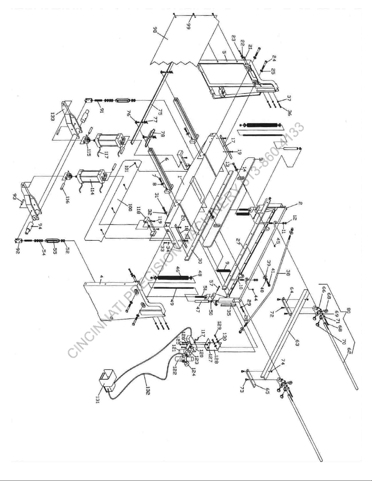
Model 36A and 52A Parts List
INDEX
NO. 36 52 DESCRIPTION QTY. NO. 36 52 DESCRIPTION QTY.
1 10101 10151 TABLE 1 99 05545 05545 SCREW, FRONT GUARD PANEL 6
2 10102 10152 CUTTER BAR 1 100 10256 10306 GUARD PANEL, REAR 1
3 10103 10153 HOLDDOWN 1 101 05546 05546 SCREW, REAR GUARD PANEL 4
4 10051 10051 R.H. SIDE PANEL 1 114 70707 AIR CYLINDER 1
5 10052 10052 L.H. SIDE PANEL 1 114 70707 AIR CYLINDER 2
6 10053 10053 FRONT ARM EXT. 2 115 70708 CLEVIS, CYLINDER 2
7 05055 05055 SCREW, FRONT ARM EXT. 4 115 70708 CLEVIS, CYLINDER 4
8 05673 05673 WASHER, FRONT ARM EXT. 4 116 70709 70709 PIN, CYLINDER 2/4
9 10054 10054 SPRING, HOLDDOWN 2 117 70710 70710 CYLINDER CORD ASSEMBLY 1
10 10111 10164 STUD, HOLDDOWN SPRING 2 118 10260 10310 CYLINDER BRKT. 1/2
11 05880 05880 NUT, HOLDDOWN STUD 2 119 05500 05550 ADJ. SCREW, CYLINDER BRKT. 2/4
12 05907 05907 CAP NUT, HOLDDOWN STUD 2 120 70711 70711 FOUR WAY VALVE 1
13 05060 05060 SCREW, HOLDDOWN 2 121 70712 70712 OILER 1
14 05673 05673 WASHER, HOLDDOWN SCREW 2 122 70713 70713 AIR REGULATOR 1
17 10055 10055 SCALE, L.H. TABLE 1 123 70714 70714 MUFFLER 1
18 10056 10056 SCALE, R.H. TABLE 1 124 70715 70715 AIR PRESSURE GAUGE 1
19 05021 05021 SCREW, TABLE SCALE 4 125 05551 05551 SCREW, VALVE MOUNTING 3
20 05639 05639 WASHER, TABLE SCREW 4 126 05552 05552 WASHER, VALVE MOUNTING 3
21 05327 05327 SET SCREW, TABLE ADJ. 2 127 05553 05553 NUT, VALVE MOUNTING 3
22 05035 05035 SCREW, TABLE LOCK 2 128 10311 10311 MOUNTING BRKT. 1
23 05670 05670 WASHER, TABLE LOCK SCREW 4 129 05554 05554 SCREW, MOUNTING 2
24 05075 05075 BOLT, TABLE 4 130 05555 05555 WASHER, MOUNTING 2
25 05676 05676 WASHER, TABLE BOLT 4 131 70716 70716 AIR FOOT SWITCH COVER PLATE 1
26 05925 05925 NUT, TABLE 4 132 70717 70717 FOOT SWITCH CORD ASSEMBLY 1
27 10105 10155 KNIFE, UPPER 1 133 10262 10312 FOOT PEDAL ASSEMBLY 1
28 05033 05033 SCREW, UPPER KNIFE 7/9
29 05670 05670 WASHER, UPPER KNIFE 14/18
30 10106 10156 KNIFE, LOWER 1
31 05035 05035 SCREW, LOWER KNIFE 6/8
32 05670 05670 WASHER, LOWER KNIFE 12/16
33 05246 05246 SET SCREW, LOWER KNIFE ADJ. 6/8
34 05759 05759 NUT, LOWER KNIFE ADJ. 6/8
35 10064 10064 SHIM, C’BAR 2
36 05249 05249 SCREW, C’BAR SHIM 6
37 05762 05762 NUT, C’BAR SHIM SCREW LOCK 6
38 10107 10157 STRAIGHTENER ROD, C’BAR 1
39 05673 05673 WASHER, STRAIGHTENER ROD 3
40 05787 05787 NUT, STRAIGHTENER ROD 3
41 10112 10165 ADJ. SCREW, STRAIGHTENER ROD 1
44 05331 05331 SET SCREW, BACKGAUGE ROD 2
45 05331 05331 SET SCREW, HOLDDOWN LOCK 2
46 10302 10302 SPRING, FOOT PEDAL 2
47 15053 15053 SPRING GUIDE 2
48 15057 15057 CAP, SPRING 4
49 15055 15055 STUD, SPRING 2
50 05787 05787 NUT, SPRING STUD 8
51 10069 10069 LINKAGE BOLT, C’BAR 2
52 05827 05827 NUT, LINKAGE BOLT, C’BAR 2
54 05826 05826 NUT, STUD 8
55 10071 10071 TURNBUCKLE 2
57 06354 06354 PIN, LINKAGE, MOUNTING 2
62 10058 10058 ROD, BACKGAUGE 2
63 10110 10163 STOP, BACKGAUGE 1
64 10065 10065 R. EXT. BAR, BACKGAUGE 1
65 10066 10066 L. EXT. BAR, BACKGAUGE 1
66 10059 10059 ADJ. BLOCK, BACKGAUGE 2
67 10060 10060 ADJ. DIAL, BACKGAUGE 2
68 10075 10075 ADJ. SCREW, BACKGAUGE 2
69 05762 05762 NUT, ADJ. SCREW 2
70 10061 10061 LOCK SCREW, BACKGAUGE 4
71 10062 10062 ADJ. BRKT. BACKGAUGE 2
72 05027 05027 SCREW, EXT. BAR 2
73 05325 05325 SWIVEL BOLT 3
74 10109 05765 NUT, SWIVEL BOLT 2
75 10159 10159 STOP, FRONT MATERIAL 1
76 10074 10074 “T”-NUT 3
77 05938 05938 WING NUT, “T”-NUT 3
78 10063 10063 BEVEL GAUGE 1
80 10108 10158 BACKGAUGE ASSEMBLY 1
91 10302 10302 STUD 2
92 10303 10303 CLEVIS, FOOT PEDAL 2
93 05544 05544 PIN, FOOT PEDAL CLEVIS 2
94 10304 10304 PIN, PEDAL BAR 2
98 10255 10305 GUARD PANEL, FRONT 1
4

FOREWORD
This manual has been prepared for the owner and operators of the TENNSMITH Model 36A and 52A Shears.
Its purpose, aside from operation instruction, is to promote safety through the use of accepted operating procedures.
Read all instructions thoroughly before operating your shear.
Also contained in this manual is the parts list for your shear. It is recommended that only TENNSMITH factory
authorized parts be used for replacement parts.
WARRANTY
Your shear has a three year limited warranty from the date of purchase. The terms of the warranty are stated on the
warranty registration card shipped with your machine. Please complete and return this card to activate your warranty.
SAFETY INSTRUCTIONS
1. Know the safety and operating instructions contained in this manual prior to operation of this shear. Beco
familiar with and understand the hazards and limitations of this shear. Always practice safety.
2. Wear approved eye safety protection, such as safety glasses or goggles, etc., when operating the shear to
protect your eyes.
3. Protective type footwear should be worn, and jewelry such as rings, watches, necklaces, etc., should be
removed prior to operation of this shear.
me
4. Do not remove the front hold-down guard (Index # 3). This is a protective device. If
the hold-down is inoperable, immediately disconnect the power and lock the main
power to the machine, and contact Tennsmith or your authorized distributor for a
replacement part.
5. Keep the hold-down (Index #3) at the minimum gap required to feed the material into
the shear. The gap should never be higher than 3/16” from the table. If you have questions
regarding the Hold-down, please consult the factory.
6. Always keep hands clear of the blade.
7. Do not misuse the shear by using it for other than its intended purpose.
8. Never exceed the rated capacity of this machine.
9. Keep the work area clear and clean to avoid tripping or slipping.
10. Always disconnect the power to the shear prior to performing any maintenance or adjustments to the machine.
11. Turn off machine when not in use.
12. Any malfunction or abnormality pertaining to this machine should be reported to the maintenance supervisor
immediately.
5

RECEIVING THE SHEAR
Examine the shear and accessories package for evidence of any possible damage sustained during transit. Any
damage should be reported to your distributor immediately.
INSTALLING THE SHEAR
Carefully remove the shear from the shipping pallet. Locate the shear in a well-lighted area on a solid level floor. Use
lag screws or bolts with expandable shields or similar holding devices through the mounting feet, located on the bottom
of the side panels.
Place an accurate machinist level on the table top, and check the level of the machine in both directions. Use metal
shims between the floor and the shear mounting surface to adjust the level. After the machine is level, tighten the
mounting bolts. Periodically, recheck the unit for levelness.
NOTE: Proper levelness greatly affects the performance of your shear, it is very important to ensure your machine is
level prior to operation.
The 36A and 52A shear is available only for air operation. Only certified technicians should perform air connections an
any necessary maintenance on this machine. If you have any questions, please consult Tennsmith.
OPERATION INSTRUCTIONS
d
The mild steel capacity of the Model 36A and 52A shear is 16gauge. Included in the manual is a standard shearing,
bending, and forming conversion chart for various materials including Aluminum, Stainless, and Plastics. If you have
any capacity related questions on materials that do not appear on the chart, please contact Tennsmith technical sup
to help determine the exact capacity ratings.
port
NEVER ATTEMPT TO SHEAR ANY MATERIAL GREATER THAN THE MAXIMUM RATING FOR
YOUR SHEAR.
The 36A and 52A is a fixed angle designed machines. Reducing the maximum width of your material does not increase
the capacity rating of this shear.
Never attempt to shear any material which would be less than a ½” cut across the full length
of the table under full capacity.
BLADE GAP ADJUSTMENT
The factory setting for the gap between the upper and lower blade is .002. This setting is the optimal clearance for the
entire range of material likely to be sheared on this machine. Different materials and thickness may require a larger or
slightly smaller clearance. If you have any specific questions regarding optimal blade gap, please consult Tennsmith.
To adjust the blade gap of your shear, the turnbuckles (55) are utilized to move the cutter bar down and hold the
position while the blade adjustment is being made. Please note: when checking the blade clearance between the
blades at any particular point across the travel of the bed, check the gap at the point where the upper blade intersects
the lower blade by 1/8” depth.
6

To start, disconnect the main air supply connection to the shear.
t side
u
es
a ¼
er
e of
.
ches
s
1. Loosen the jam nuts (54) that lock the turnbuckle in position.
2. Move the cutter bar down by tightening each turnbuckle. To avoid putting the cutter bar in a bind, tighten each
turnbuckle evenly. The first checkpoint when verifying or changing the blade gap is 2 inches from the righ
end of the blade facing the machine. Make sure the upper blade intersects the lower blade by 1/8”. Once yo
have moved the cutter bar into the desired position, use a set of shim feeler gauges to verify the blade
clearance between the two blades. The second checkpoint is the center of the shear, and the last is 2 inch
from the left end of the blades.
3. To close the gap on the either the left or the right ends of the blade, loosen the table bolts(24) for the particular
end you are adjusting, and loosen the 9/16” adjustment screw (22) located in the front of your side panel by
turn. Next tighten the set screw (21) to move the lower blade towards the upper blade. When you have
reached the desired gap verified by your feeler gauge, tighten the adjustment screw (22) to ensure the prop
tension on the set screw. To open the gap, reverse the previous procedure.
4. After you have reached the desired gap, tighten the table bolts (24) on each side.
5. The blade gap in the center of the shear is controlled by the adjustment screw (40) located on the backsid
the cutter bar of the shear. To close the gap, tighten the screw in ¼ increments until you have reached the
desired gap.
6. After you have adjusted the shear gap to the desired settings, move the cutter bar back to its original settings
This is called the pitch or rake of the blade:
Rake angle settings:
MODEL 36A
Use a marker to mark the shear bed 2 inches to the from the right side edge of the table. Next, measure over 32 in
from the right side edge of the table and make another mark. Starting at the right hand side (facing the machine) at the
7
designated mark on the table, rotate the turnbuckle (55) until the distance between the top and bottom blades is
approximately 3/8 of an inch. At the opposing end, repeat the procedure allowing 1 ¾ inches clearance between the
upper and lower blades. After you have the desired clearance between the upper and lower blades slightly adjust the
turnbuckles so that they have an equal amount of tension. That is, if one turnbuckle has more play or lost motion in it
than the other, it should be readjusted accordingly. Once the rake has been set and equal tension verified between the
turnbuckles, retighten the jam nuts (54) and lock the turnbuckles in place.
MODEL 52A
Use a marker to mark the shear bed 2 inches to the from the right side edge of the table. Next, measure over 48 inche
from the right side edge of the table and make another mark. Starting at the right hand side (facing the machine) at the
designated mark on the table, rotate the turnbuckle (55) until the distance between the top and bottom blades is
approximately 3/8 of an inch. At the opposing end, repeat the procedure allowing 1 ¾ inches clearance between the
upper and lower blades. After you have the desired clearance between the upper and lower blades slightly adjust the
turnbuckles so that they have an equal amount of tension. That is, if one turnbuckle has more play or lost motion in it
than the other, it should be readjusted accordingly. Once the rake has been set and equal tension verified between the
turnbuckles, retighten the jam nuts (54) and lock the turnbuckles in place.

HOLD-DOWN ADJUSTMENT
CAUTION: THIS SHEAR SHOULD NOT BE OPERATED WITHOUT THE HOLDDOWN IN
PLACE AND PROPERLY ALIGNED. The hold-down (3) is designed to engage the material before the blades
yet allow only minimal clearance between the guard’s feet and the table surface. The gap between the hold-down
feet and table surface should never be above 3/16” of an inch. The gap between the hold-down and the table is
controlled by turning the nut on the hold-down studs (11). Clockwise rotation will increase clearance; counter clockwise
turns will decrease the gap.
The guard should be held snug against the milled pads on the cutter bar and not feel loose. You must be careful,
however, that the hold-down bolts (13) are not so tight as to bind the guard when the cutter bar is in the down position.
Properly aligned, the bolts will snug but still allow rotation of the hold-down screw washers (14). At the rear of the cutter
bar you will find two tapped holes wherein hold-down jam screws (45) are located. Once you have applied proper
tension to the hold-down screws, tighten the jam screws to lock alignment in place. (Note: The milled pads on the front
and rear of the hold-down should be greased periodically to maintain proper action.
BACK GAUGE ADJUSTMENT
Slide back gauge rods (62) through the adjustment blocks (66) and brackets (71). Mount the rods in the holes found at
the rear of the cutter bar. Move the gauge angle (63) up the rods until it contacts with the lower blade. Observe the
pointers attached to the adjustment blocks and adjust the rods in or out until the embossed scales read zero on the
pointers. Tighten the set screws (44) to lock the rods in place.
To attain a particular setting, loosen the four lock screws (70) and slide the gauge to an approximate position. Fine tune
adjustments are accomplished by locking the screws of the two adjustment brackets (71) while keeping those of the
blocks (66) loose. The adjustment dial (68) can then be used to position the gauge in or out.
8

SHARPENING BLADES
Your TENNSMITH shear features “Tri-Action” ground blades. The upper blade has two cutting edges which are ground
with a 2 degree edge relief. The upper blade can be turned over to expose the new cutting edge. It can be sharpened
on a surface grinder by grinding both wide sides to the blade. The lower blade has one cutting edge with a 2 degree
cutting edge relief and a 1 degree face relief. It can be sharpened on a surface grinder by grinding the wide side of the
blade having the 1 degree relief. See Figure 2). Blade sharpening service is available from the factory.
9

10
MACHINE SPECIFICATIONS
Model 36A
Maximum shearing capacity, mild steel 16 gauge / 1,6mm
Maximum shearing capacity, stainless steel 20 gauge / 1,0mm
Maximum cutting length 52-1/4 in. / 1327mm
Back gauge range 30 in. / 762mm
Front gauge range 37 in. / 940 mm
Floor space, gauges in position 45 x 80 in. / 1143 x 2032 mm
Overall dimensions, less gauges, LxWxH 46-1/4 x 24 x 42 in. / 1181 x 686 x 1067 mm
Strokes per minute, full length 40
Maximum operating pressure 75 psi / 5.1 atmos.
Air consumption per stroke 1.1 cu. ft. / 0.031 cu. m
Shipping weight 800 lbs. / 363 kg
Model 52A
Maximum shearing capacity, mild steel 16 gauge / 1,6mm
Maximum shearing capacity, stainless steel 20 gauge / 1,0mm
Maximum cutting length 52-1/4 in. / 1327mm
Back gauge range 30 in. / 762mm
Front gauge range 37 in. / 940 mm
Floor space, gauges in position 60 x 80 in. / 1524 x 2032 mm
Overall dimensions, less gauges, LxWxH 61 x 25 x 42 in. / 1550 x 915 x 1067 mm
Strokes per minute, full length 40
Maximum operating pressure 75 psi / 5.1 atmos.
Air consumption per stroke 1.33 cu. ft. / 0.038 cu. m
Shipping weight 1300 lbs. / 590 kg
APPROXIMATE SHEARING, BENDING AND FORMING
CAPCITIES FOR VARIOUS MATERIALS COMPARED TO MILD STEEL
Mild Steel Capacity 20ga. 18ga. 16ga. Mild Steel Capacity 20ga. 18ga. 16ga.
NON-FERROUS METALS FERROUS METALS
Aluminum Iron-dead soft 20ga. 18ga. 16ga.
1100-0, 2024-0 .070 .090 .125 Steel low carbon
5052-0. 6061-T4 .070 .090 .125 1074, 1095 C.R. Spring Steel 24ga. 22ga. 20ga.
2024-T3, 5052-H34 .048 .063 .090 Hot Rolled 20ga. 18ga. 16ga.
5086-H36, 6061-T6 .048 .063 .090 Low carbon Cold Rolled 20ga. 18ga. 16ga.
Copper and Alloys Stainless Steel Annealed 24ga. 22ga. 20ga.
Electrolytic Copper 18ga. 16ga. 14ga. OTHER MATERIALS
Bronze Commercial 18ga. 16ga. 14ga. Plastics
Brass 70-30 18ga. 16ga. 14ga. ABS Compounds .120 .150 .200
Nickel Alloys Polycarbonate .075 .105 .125
Inconel 600 24ga. 22ga. 20ga. Printed Circuit Boards
Monel R405 24ga. 22ga. 20ga. Copper-Clad
Nickel 200A Annealed 24ga. 22ga. 20ga. Epoxy Laminate .086 .115 .150
Zinc as Rolled 20ga. 18ga. 16ga.
Approximate Gauge Equivalents
Gauge 28 26 24 22 20 18 16 14 12 11 10
Inches .015 .018 .024 .030 .036 .048 .060 .075 .105 .120 .135
Millimeters .38 .46 .61 .76 1.00 1.25 1.60 2.00 2.70 3.05 3.50
6926 Smithville Hwy. McMinnville, TN 37110
Phone: (931) 934-2211 • Fax (931) 934-2220
www.tennsmith.com

11

12
3-YEAR LIMITED WARRANTY
TENNSMITH machinery and component parts are carefully inspected at various stages
of production and are tested and inspected prior to shipment. We agree that for a period
of twelve (12) months from the date of delivery from our authorized distributor to
replace, at our option, any machine (or component part thereof) proving defective within
the above period. Additionally, we agree that for a period of thirty-six (36) months from
date of delivery to replace component parts proving defective within the stated period.
All warranty claims are made F.O.B. our plant, providing such machine (or component
part) is returned freight prepaid to our plant, or a designated service center of the
undersigned, for our examination. This warranty does not include repair or replacement
required because of misuse, abuse, or because of normal wear and tear; or electrical
components which are warranty by their manufacturer. Further, we cannot be
responsible for the cost of repairs made or attempted outside our factory or designated
service center without our authorization. No claims for defects will be honored if the
name and data place has been remove. This warranty is made expressly in place of all
other warranties or guarantees express or implied, with respect to fitness,
merchantability, quality or operative ness. This warranty becomes effective only when
the accompanying warranty card is fully and properly filled out returned to the factory
within ten (10) days from date of delivery.
6926 Smithville Hwy. McMinnville, TN 37110
Phone: 931-934-2211 • Fax: 931-934-2220
www.tennsmith.com
Proudly Made in the USA
A Family Tradition Since 1928
This manual suits for next models
1
Table of contents
Other Tennsmith Power Tools manuals
Popular Power Tools manuals by other brands

Ryobi
Ryobi R18PI instruction manual

MULTIPRESS
MULTIPRESS M6P Series Operating instructions and service manual

Chicago Electric
Chicago Electric 61924 owner's manual

EINHELL
EINHELL GC-MT 2236 Original operating instructions

Makita
Makita BST220 instruction manual

Textron
Textron GREENLEE GATOR LS50L Operation manual

IMI NORGREN
IMI NORGREN PGS10 User instructions

TE Connectivity
TE Connectivity 354940-1 instruction sheet

GÜDE
GÜDE AKT 4.10-4 Translation of the original instructions

EINHELL
EINHELL Royal SKS 85 E operating instructions

AL-KO
AL-KO Solo MT 42 Translation of the original instructions for use

Shop fox
Shop fox W1702 manual