WÜRGES MR 1 User manual

Würges Vibrationstechnik GmbH
Daimlerstraße 9
D-86356 Neusäß
Telephone +49 8 21 99 98 24-00
Telefax +49 8 21 99 98 24-10
E-Mail [email protected]
Web www.wuerges.de
(Translation of the Original Instruction Manual)
Installation and Operating Instructions
Magnetic Vibrator MR 1

2
1. General Information Page 3
2. Symbols Used Page 4
3. Safety Page 5
3.1. Intended use
3.2. Skilled personnel qualifications
3.3. General safety instructions
4. Technical Data Page 7
5. Transport and Storage Page 8
6. Installation and Startup Page 9
6.1. Assembly/Installation
6.2. Electrical connection/Cable connection
6.3. Intensity adjustment
7. Servicing and Maintenance Page 13
8. Spare Parts Page 14
9. Disposal and Recycling Page 16
10. Warranty Page 16
Appendix Page 17
• EU Declaration of Conformity
Contents

3
Würges magnetic vibrators are designed and
built to state-of-the-art standards and operate
safely if used as intended.
They conform to the Electromagnetic Compa-
tibility Directive 2014/30/EU and the Low-Vol-
tage Directive 2014/35/EU.
The Operating Instructions have to be read
and understood by every person at the user’s
company who is assigned with assembly,
setting up, start up, the maintenance and
repair of vibration motors. This also applies
for additional instructions in case of modified
devices.
The instruction manual must be
read carefully and in full before
using the vibrator motors.
1. General Information

4
The following information and hazard symbols are used in these installation and operating
instructions:
2. Symbols Used
ATTENTION Important information regarding operations or
procedures to which particular attention is to
be paid.
EXPLOSION HAZARD Refers to the possibility of fatal, severe or
irreversible injuries caused by use of the
product in an explosive atmosphere.
HAZARD Refers to the possibility of fatal, severe or
irreversible injuries caused by live parts.
WARNING Refers to the possibility of fatal, severe or
irreversible injuries caused by general hazards.
HOT SURFACE Refers to the possibility of severe or irrevers-
ible injuries caused by touching hot surfaces.
DISCONNECT Refers to the fact that the motor must be
MOTOR FROM MAINS disconnected from the electricity mains and
secured against being switched back on
again before any work is carried out on the
motor.
ENVIRONMENTALLY Refers to the obligation to ensure environ-
COMPATIBLE DISPOSAL mentally compatible disposal.

5
3.1. Intended use
Electric vibrators are not independently
functioning machines. They are used as the
drives of vibrating machines such as vibratory
conveyor troughs, conveyor pipes, screening
machines, grading/sorting machines and
knock-out grids.
These machines use vibrations to screen,
convey, remove, compact and sort or grade.
Any other use is deemed to be not as inten-
ded or misuse.
Electric vibrators are designed to generate
forces that can be destructive.
The vibrating machine must be designed for
the forces generated by the electric vibrators.
The operator shall bear responsibility for the
operation of vibration motors in explosion
hazardous areas.
3.2. Skilled personnel qualifications
The installation/assembly, startup and main-
tenance may only be carried out by authorised
and qualified skilled personnel.
3. Safety

6
3.3. General safety instructions
Magnetic vibrators generate vibrations. The owner of vibration machines must
protect their employees against actual or possible risks to their health and safety
caused by the effect of vibrations.
Würges Vibrationstechnik GmbH refuses to accept the responsibility for any
damage to property or personal injuries if technical changes have been made to
the product or the instructions and regulations in this instruction manual have
not been noted and followed.
Live parts can cause severe or fatal injuries.
Electric vibrators must be safely disconnected from the electricity mains before
any work is carried out on them. The required procedure is as follows:
1. Switch off vibrator motor
2. Secure against being switched back on again
3. Test for safe disconnection from the power supply
4. Allow the vibrator motor to cool
Do not touch the vibrator motors while they are running or soon after switching
them off. The surface temperature of the vibrator motors can reach such high
values during operation that there is a risk of burns.
Always use a torque wrench when Tightening screws or bolts! Tightening
torques see page 9.
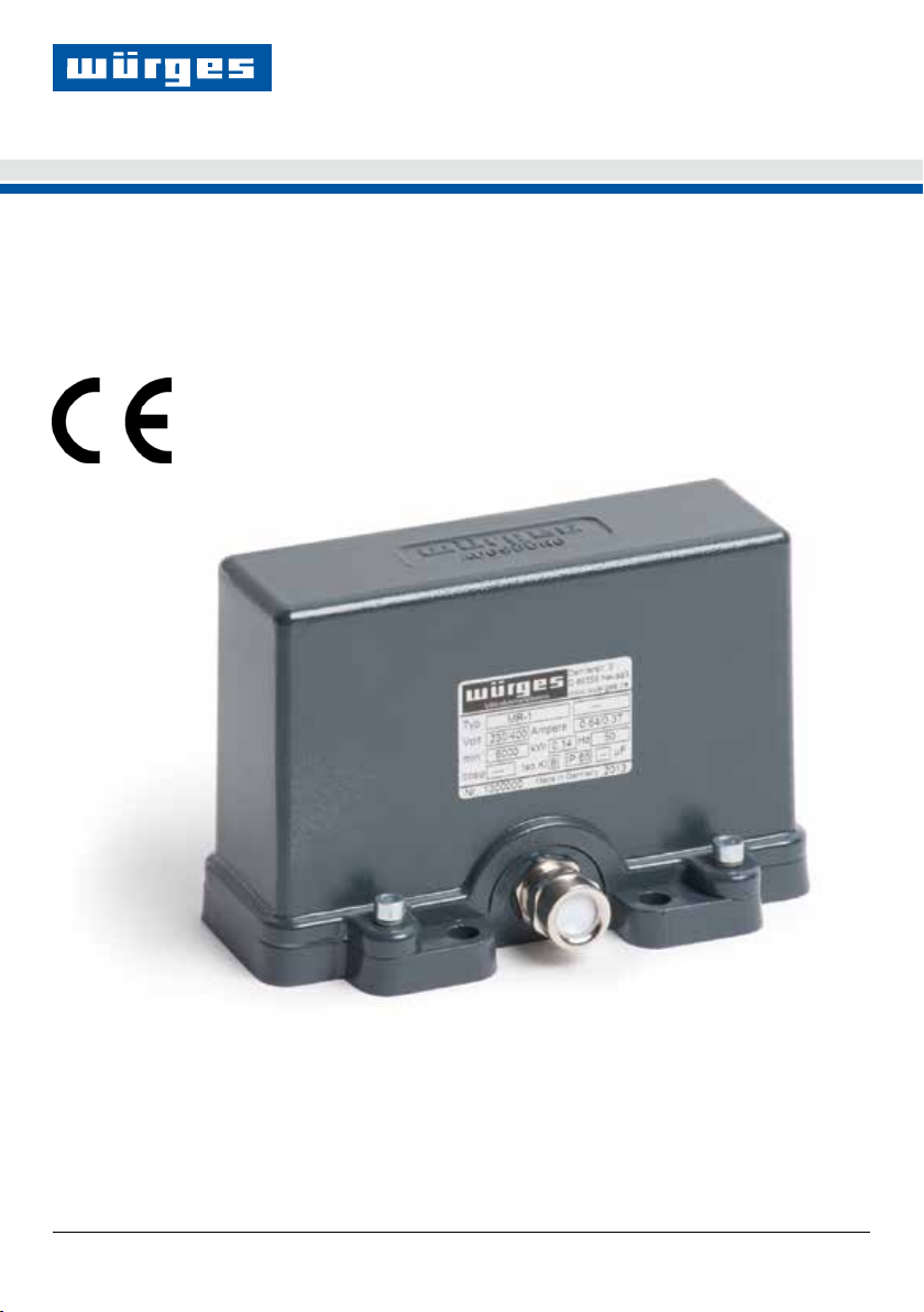
MR 1 series magnetic vibrator motors may not be used in hazardous areas (po-
tentially explosive atmospheres).

7
4. Technical Data
1. Type designation
2. Mains voltage
3. Speed
4. Thermal insulation class Y
(80°C)
5. Serial number
6. IP protection
7. Mains frequency
8. Year built
9. Power input
10. Nominal current
Please see our catalogue for additional technical dara.

8
When they are delivered the vibrators must be
checked for visible transport damage!
If the vibrator is visibly damaged
it must not be started up. The
vibrator must be examined and if
necessary returned to the manu-
facturer for repair.
Until they are installed the magnetic vibrators
should be stored in enclosed, dry rooms at a
max. ambient temperature of 40° C.
Vibrators must always be stood on their bases
or footings! Do not stack vibrator motors!
Do not lift up the vibrator by its
installed connection cable.
Note and follow the local accident prevention
regulations.
5. Transport and Storage

9
6.1. Assembly/Installation
Magnetic vibrators can be installed in any in-
stallation position. Vibrators may only be built
on to machines with flat, oil, grease and paint-
free and flexurally rigid mounting surfaces.
Surface quality:
Only bolts in quality class 8.8 > EN ISO 4014
(DIN 931); EN ISO 4017 (DIN 933) and nuts
in quality class 6 > 8.8 EN ISO 4032 (DIN934)
may be used.
The bolts must be secured against mechani-
cal loosening by Schnorr washers, type VS,
Nord-Lock washers or RIPP LOCK® washers.
The fixing bolts must be checked
for secure fit after approx. two
operating hours and if necessary
retightened. Other checks should
be carried out daily!
Improper fixing results in the
breakage of the feet of the
magnetic vibrator.
6. Installation and Startup
Minimum tightening torque
M 8
30 Nm
Mounting plate
Vibrator foot/flange
correct correct incorrect
✓ ✓

10
Electric vibrators must be safely dis-
connected from the electricity mains
before work is carried out on them.
The required procedure is as follows:
6.2. Electrical connection/Cable connection
The electrical connection may only be made
by a qualified electrician or person who has
received the necessary electrical instruction in
accordance with EN-60204-1.
The mains voltage and frequency must corre-
spond to the nameplate data. The motor must
1. Switch off vibrator motor and secure
against being switched back on again
2. Check for safe isolation from supply
3. Allow the motor to cool
only be connected to an electricity system that
conforms to the VDE provisions.
Each motor must have its own upstream motor
protection device as protection against possible
overload; the nominal current of this protective
device must be set according to the nameplate
data.

11
Use only a flexible cable for connection.
We recommend the following cable type:
H 07 RN-F 3G1,5
Plastic cable is unsuitable.
Fit cable end sleeves onto cable ends. In no
case solder on since the stranded wires might
break near the solder joint.
Insert cable into the vibrator and connect it acc.
to the circuit diagram above. (See page 10).
When tightening the union nut screw connecti-
on make sure that the cable sheath still is fully
covered by the seal. If this is not followed, the
cable is not clamped in place, not strain relieved
and not waterproof.
Carefully close the vibrator with seal and screw
lock.
The motor connection line has to be securely
fastened approx. 0.5m after leaving the motor.
The first line attachment point and the motor
shall not be moveable against each other. The
connecting cable has to be laid in such a way
that natural vibrations are being avoided and
there will be no tensile load.
Check the current input when the motor is ope-
rated for the first time. It should be greater than
the value stated on the type plate, remedy the
situation by decreasing the centrifugal force
(see Chapter 7).
Check the line for chafe marks from time to
time and eliminate the cause for this where
applicable.

12
6.3. Intensity adjustment
The vibration effect with magnetic vibrators de-
pends on the payload and the adjusted air gap
between magnet (Pos. 10 ) and rotor (Pos. 3).
Factory setting air gap:
230 V: 1,8 mm
400 V: 1,6 mm
Stronger effect calls for a smaller air gap and
vice versa. With the protective hood removed,
the air gap is adjusted using pluggable brass
spacer plates (Pos. 14 and 15). With both nuts
(Pos. 7) unscrewed, the air gap can be change
can be changed by removing or adding spacer
plates between rubber pad (Pos. 13) and
rotor (Pos. 3). Both sides need to be adjusted
equally.
The required spacer plates are stocked bet-
ween the ballast discs (Pos. 11).
Noise generated by wrong
adjustment.
The rotor thuds onto the magnet
with too small air gap causing a
loud rattling noise. This is imper-
missible and has to be stopped
by widening the air gap.

13
Maintenance is not necessary since there are
no wear parts.
7. Maintenance and Repair

14
State the following when ordering spare parts:
• Motor number
• Device type
• Description, position and
part order number
• Required quantity
See exploded drawing on page 15 for further
information.
We only assume warranty for original spare
parts supplied by us.
We expressly point out that original spare
parts and accessories that were not supplied
by us have not been tested and released by
us. Therefore, installation and/or deployment
of such products may possibly change given
design characteristics to produce negative
effects thus posing an active and/or passive
risk to safety.
Würges excludes any liability and warranty in
cases where damage arises by using non-ori-
ginal spare parts and accessories.
8. Spare Parts

15
Spare parts list MR 1
No. Order No. Pieces
1 05501 1
2 05601 1
3 05701 1
4 21601 2
5 22301 4
6 22501 2
7 28201 2
9 29491 1
No. Order No. Pieces
10 62101 1
11 75351 32
12 75831 1
13 76201 2
14 76501 0,5 mm ~ 8
15 76511 0,2 mm ~ 8

16
Packaging material and motor parts have to
be disposed of in an environmentally compa-
tible manner.
Steel:
Weights, screws, nuts
Aluminium:
Base plate, protective hood, rotor
PE:
Seals
Copper and synthetic resin:
Magnet
We take back equipment for
professional disposal!
Delivery must be carriage free.
9. Disposal/Recycling
Würges provides warranty for 1 year, be-
ginning with delivery, for all new magnetic
vibrator.
Warranty expires when:
• the motor is connected wrong, or connec-
ted with wrong voltage,
• the motor fails because of missing or wrong
electric protection,
• there were changes made to the motor,
• the motor was damaged during transport,
• the motor was not installed as shown in
chapter 6,
• the motor was connected with wrong cable,
• there is misuse/not intended use,
• the instructions of the manual are not
followed.
10. Warranty

17
Hereby declares the manufacturer
Würges Vibrationstechnik GmbH, Daimlerstr. 9, 86356 Neusäß:
The magnetic vibrators of the series
MR
Are conform to the following European directives:
2014/35/EU (Low Voltage)
2014/30/EU (EMC)
2011/65/EU (RoHS)
The compliance with the provisions of the directives is proved by the following standards:
EN ISO 12100 / 2011
EN 61000-6-2 / 2011
EN 61000-6-4 / 2011
The manufacturer will electronically transmit the specific documents to national bodies on request.
The designated product is to be seen as a component for installation into a machine or system.
Commissioning is prohibited until the conformity of the final product to the directive 2006/42/EC is
established.
The safety instructions of the product documentation must be duly observed.
This declaration of conformity is no warranty of the characteristics in the sense of product liability.
Neusäß, 01.06.2017
Würges Vibrationstechnik GmbH
Dipl.-Ing.(FH)
Philipp Würges
General Manager
EU Declaration of Conformity

18
Notes

19
Notes

20
Würges Vibrationstechnik GmbH
Daimlerstraße 9
D-86356 Neusäß
Telephone +49 8 21 99 98 24-00
Telefax +49 8 21 99 98 24-10
E-Mail [email protected]
Web www.wuerges.de
© 06/2017
Table of contents
Popular Power Tools manuals by other brands

Cleco
Cleco 48EAE51P3 instruction manual

Central Hydraulics
Central Hydraulics 45860 Operating information

Bauer
Bauer 2028E-B user manual

Parkside
Parkside 285196 Operation and safety notes translation of the original instructions

Makita
Makita DJS160 instruction manual

Bartell
Bartell BCF1080 Owner's manual and parts book