Tennsmith LM1010-2x User manual

Model LM1010 Performance “R”
Operation, Parts and Maintenance Manual
Model LM1010-2x
Model: Prepared for:
Serial #: Date of Manufacture:
Options: Inspected By:
Notes:
6926 Smithville Hwy. McMinnville, TN 37110
Phone: 931-934-2211 • Fax: 931-934-2220
www.tennsmith.com
Proudly Made in the USA
A Family Tradition Since 1928

1
TABLE OF CONTENTS
SUBJECT PAGE NUMBERS
SHEAR SPECIFICATIONS…………………………………… 2
SAFETY LABELING AND INSTUCTIONS…………………. 3-6
INSTALLATION………………………………………………. 6
OPERATING INSTRUCTIONS………………………………..7-8
BLADE CLEARANCE/ADJUSTMENT……………………….9
BLADE ROTATION/REPLACING……………………………10-11
BACKGAUGE INFORMATION……………………………… 11
HOLDDOWN INFORMATION………………………………..11
SHEET SUPPORT SYSTEM INFORMATION………………..12
MAINTENANCE……………………………………………….12
WARRANTY INFORMATION……………………………….. 13
PARTS VIEW AND DESCRIPTIONS…………………………14-24
ELECTRICAL DIAGRAM AND PARTS LIST………………. 25-28

2
LM 1010 Specifications
Maximum Shearing Capacity, Mild Steel 10 gauge/3,5mm
Maximum Capacity of Mild Steel is rated at 80,000 psi tensile 44,000 yield
Maximum Shearing Capacity, Stainless Steel 14 gauge/2,0mm
Maximum Capacity of Stainless Steel is rated at 90,000 psi tensile 55,000 yield
Maximum Cutting Length 121 in/3073mm
Back gauge Range 30 in/762mm
Strokes per Minute 31
Number of Hold downs 16
Motor-230/460v, 3-phase, 60Hz 12.5 hp
Overall Dimensions, Less Gauges, LxWxH 145 x 39 x 59-1/2 in
Floor Space, Gauges in Position 145 x 78 x 59-1/2 in
Shipping Weight 9,400 lbs

3
ATTENTION
Please verify that the following safety decals are attached to the LM Shear. If you do
not locate all of the decals, please contact Tennsmith to replace any missing or
unreadable safety labels.
NEVER operate this machine without the proper safety
labeling.

4

5
SAFETY INSTRUCTIONS
1. Do not operate service or perform maintenance prior to reading and
understanding the instruction manual. Become familiar with and understand
the hazards and limitations of your shear.
2. Wear approved eye protection and protective footwear while operating the
machine.
3. Be certain this machine is properly wired and grounded to conform to the
National Electric Code. The connection of this machine to the power source
should only be made by and inspected by a qualified electrician.
4. Keep hands and body parts clear of the hold down, cutter head and blade
area.
5. Do not exceed the rated capacity of the machine.
6. Never leave the machine in a power on condition when unattended.
7. Always disconnect the machine from the power source before attempting
maintenance, repairs or adjustments.
8. DANGER: Do not attempt to remove the hold down before inserting and
bottoming out the hold down compression bolts (71). The compression bolts
were shipped with the machine. When receiving the shear the bolts are
located inside of the electrical box. Please remove them and store them in a
location to be accessible.
9. Do not remove guards unless required to service the machine. Replace all
protective covers prior to operation.
10. Always wear gloves to protect your hands when handling the shear blades.

6
11. Insure that the point of operation safeguarding is provided, used and
maintained for any applicable use or service which exposes bodily hazards.
For more details please refer the ANSI Standards for Shear Operations.
12. Keep the Work area around this machine clear and clean to avoid tripping
or slipping.
INSTALLING THE SHEAR
The unit is shipped with a lifting bolt attached on the top of the cutter head. The shear
should be lifted and positioned by using a sling or chain passed through the lifting bolt.
CAUTION: The shear weighs approximately 9,500 lbs. net. Be sure to verify the
maximum load permissible for a given chain or sling.
Locate the machine in a well lighted area on a solid level floor. Use lag screws or bolts
with expandable shields or similar holding devices through the mounting holes on each of
the unit’s side panels (22,51) The center line dimensions for the foundation holes can be
found on the diagram supplied with the manual on page (22).
The shear must be securely anchored to the floor and leveled before operating. Check the
level of the shear with a machinist level both along the length and depth of the machine.
Use the leveling screws (35) provided with the machine to achieve proper level. It may be
advisable to slip a small section of light gauge sheet metal under the leveling screws so
that their adjustment will not penetrate the floor.
ELECTRICAL SPECIFICATIONS
A wiring diagram is located in this manual and inside the electrical box (41). The
connection of this machine to the power source should only be made and inspected by a
qualified electrician. This machine should be properly grounded. Improper wiring may
result in accidental shock which could cause grave injury or death. Motor rotation should
match the directional indicators found on the motor housing. The unit is equipped with
230v/460v, 3 phase, 60Hz motor. The manufacture’s data on the motor will detail its
specifications.

7
LM Control Box Overlay

8
LM1010 SHEAR CONTROL PANEL OPERATION
Please refer to the previous page which shows the 4 functions of the control panel box on
your LM1010 Shear
1. On/Off Push/Pull Switch. This switch is located on the upper left corner of the box.
It is labeled 1. on the previous page. To operate the shear, turn the main disconnect
power switch to the on position and pull the Push/Pull switch to out position until the
light illuminates the switch. The shear is now ready to operate. Please note if your
switch does not illuminate in the out position, you must immediately replace the bulb
located within the switch. It is unsafe to operate this shear without the illuminated
switch. Please contact Tennsmith if you need assistance replacing the bulb.
2. To the right of the Push/Pull Switch is the Jog/Run Switch. This selector type switch
is designated 2 on the previous page. In normal shearing operation this switch should be
in the Run position.
3. The Jog Button is located under the Push/Pull switch on the panel.
It is designated 3 on the previous page. The Jog function allows the operator to engage
the motor and move the cutter head of the shear up or down slowly and hold the cutter
head at a particular position. A secondary function of the Jog function is move the cutter
head up if material is ever wedged between the blades and stalls your machine. The
primary use of the Jog function is to check the clearance between the upper and lower
blades at various points within the shearing cycle.
To operate the Jog function, select Jog on the switch 2 in the upper right corner of the
panel. Next, select either Forward or Reverse on the switch designated 4 next to the Jog
switch, and finally push the Jog switch to move the cutter head of the shear.
Please note: if you are performing a check of the clearance or blade
gap of the shear, the shear must be in an off position at the Push/Pull
switch 1 and at the main disconnect power switch located on the outside
of the box. In addition a lockout tag must be securely placed on the
main electrical connection anytime you are verifying the blade
clearance. If you have any questions on this procedure, please consult
the factory prior to any adjustments on your shear.
4. Stroke Selector Switch This switch is located towards the bottom of the panel and is
designated 5 on the previous page. The switch has two options:
1. Cont – This is for continuous operation of the cutter head of the shear. To engage the
continuous mode, select run on switch 2 (Jog/Run Switch) and select Cont. on the stroke
selector switch. With this mode the cutter head will repeat continuously a full cycle until
the operator releases his foot from the foot pedal of the shear. This mode is useful when
cutting short strips of material that is generally 2” or less.
2. Single – With this mode, the shear will make one complete down and up cycle each
time the foot pedal is pressed. This is the standard mode of operation on this shear.
Please contact the factory if you have any questions regarding the operation of this shear.

9
BLADE CLEARANCE
The blade clearance on the LM1010 was set at the factory to .004 in. on the ends of the
blades with a .003 gap in the center of the machine. At this setting, your shear should
provide satisfactory results over a broad range of materials and thickness. However, when
shearing lighter gauge materials a tighter blade gap may be desired. Also, upon turning
the blades to a new edge or after re-sharpening the blades, the blade clearance must be
reset.
CAUTION: Checking the blade gap will require removing the wire
finger guard (80). Do not operate the shear without the guard in place.
To check the blade clearance, set the machine to the jog mode and jog
the cutter head down so that the blades just overlap at the point at
which the inspection is to take place.
WARNING:Disconnect power to the machine prior to making the
measurement. Use a feeler gauge to make the measurement.
The blade clearance adjustment is made in the following manner:
1. Loosen the two table locking bolts (49) located near the mid- section of each side
panel and then retighten the bolts hand tight.
2. Loosen the four table bolts (43), again reasserting only a slight amount of pressure
back to each one.
3. The table positioning screws (20) located at both ends of the table are the means used
to achieve the proper blade clearance. The forward screw pushes the table and bottom
blade toward the cutter head. Likewise, the rear screw adjusts the blade back, thus
increasing the clearance. To set the clearance, place a feeler gauge of the same thickness
as the desired clearance between the two blades. Adjust the forward screw outward until
the feeler gauge is locked between the blades and cannot be removed. Then adjust the
rear screw in the opposite direction until the gauge stock is freed. The opposing actions
of the screws serve to attain a tight, positive setting.
4. After setting the clearance on both ends of the machine, retighten the four table bolts
and the two locking bolts.
5. The blade clearance in the center of the machine controlled by adjusting the center
truss located at the rear of the cutter head. The blade clearance in the center of the shear
should be set at least .001 closer than the dimension chosen for the ends of the blade.
6. Reposition all protective guards and covers.
Please contact the factory if you have any question regarding this procedure.

10
REPLACING/ROTATING BLADES
The blades on the LM Series shears are four edged blades constructed of high carbon,
high chromium tool steel. Top and bottom blades are interchangeable. Upon utilizing all
four edges of you blades, you may return the blades to the factory for re-sharpening or to
a qualified blade re-sharpener, such as a blade manufacturer.
To remove and reposition the blades, the procedure is as follows:
1. DANGER: disconnect the main electrical power source to
the shear.
2. Removal of the hold down assembly (69)
A. DANGER:Never attempt to remove the hold down
assembly without inserting and bottoming out the hold
down compression bolts (1/2” x 6” bolts shipped with the
machine) which are required to contain the spring
pressure of the hold down pads while the assembly is
removed from the shear. Remove the top sheet metal cover
from the top of the hold down, and insert the compression bolts inside
the hole mounts on top of the hold down until each bolt bottoms out.
B. After bottoming out the compression bolts, remove the four hex head
bolts (81) which attach the hold down to the side panels on each end.
C. Use a sling and fork lift to remove the hold down after pulling the
assembly free of the front gib screw space collars located on the side
frames of the shear.
3. Removal of the top blade. CAUTION:Use gloves when handling
the blade to protect your hands. Place a wood block wedge between
the upper and lower blades. Loosen the top blade bolts starting at the ends of
the blade working toward the center. Rotate the blade to a new cutting edge
and reversing the procedure, reinsert and snug the bolts working from the
center out to each end.
4. With all bolts in place, securely torque the bolts while insuring that the blade
is properly seated in the machined blade slot of the cutter head by using either
a brass or wood pry bar.
5. Repeat the above procedures similarly to reposition the bottom blade.
6. Use the procedures outlined in the BLADE CLEARANCE section of this
manual to reset the proper baled gap. CAUTION: Upon repositioning
the shear blades, it is imperative that the bottom blade be
adjusted well clear of the top blade before attempting to jog
the cutter head down to make the blade clearance adjustment.

11
Otherwise, crashing of the blades could result in severe
damage to the machine.
7. Reposition the hold down assembly.
BACKGAUGE INFORMATION
The LM shear is fitted with a front operated back gauge as standard equipment. The
gauge was installed and calibrated at the factory and shipped intact mounted on the shear.
Inspect the gauge carefully to determine any possible movement or damage in transit.
The gauge has 30 inches of travel. To verify the back gauge was not disturbed during
shipping, rotate the hand wheel bringing the gauge into contact with the bottom blade.
The display should now read zero. If the display has a value other than zero and gauge is
in fact in contact with the bottom blade, the unit must be adjusted.
ADJUSTING the BACKGAUGE
When adjusting the back gauge, first determine that the two upper support shafts (123)
are inserted into the welded collars at the rear of the cutter head at equal amounts. The
factory setting is 1.5 inches from the face of the collar to each of the front two support
brackets (128). Upon verifying this dimension, notice that each support bracket has a hex
head bolt threaded into the body of the bracket. When the gauge is brought in to a zero
reading on the display, the head of these bolts contact the adjusting blocks (127) and
provide for a more definite stop for the readout. To perform the adjustment, bring the
adjusting blocks in contact with the bolts and then adjust the threaded rods (109)
connected to the stop (100) so that the stop is flush against the bottom blade at both ends
of the shear. Be certain to retighten the lock nuts (115) of the threaded rod.
Hold Down Adjustment
The following is the instructions to raise the hold down height to reduce the pressure
(Hold down) on your LM shear:
1. Using the jog mode, depress the jog button until the machine cutter head
reaches the bottom or its lowest position.
2. Disconnect the power to the machine.
3. Remove the sheet metal cover on the top of the hold down.
4. To raise the height of the hold down pad use two 7/8” wrenches unlock the
two nuts that are locked and positioned against the square tube. Turn the
bottom nut against the tube for 1 complete turn. Lock the top nut against the
bottom.
5. Replace the top sheet metal cover to the hold down.
6. Reconnect the power to the machine.
7. Verify the clearance or height has been raised.

12
SHEET SUPPORT SYSTEM
1. Single Stroke: When the foot pedal is activated, the sheet support will drop down
and remain down until the cycle is complete and then return to the up position.
2. Continuous Stroke:When the foot pedal is activated, the sheet support will drop
down and stay down as long as the foot pedal is activated. When the foot pedal is
released the cutter head will return to top of the stroke and the sheet support return to
the up position.
3. Speed of the System:The speed of the sheet support is regulated by the two flow
controls on the sheet support air valve. The pressure to the system is regulated by the
Filter / Regulator unit that the air supply connects to. Generally 80 psi on the
regulator will give consistent operation providing the incoming air supply is 90 psi or
higher (max 150 psi). The incoming air supply should also have a flow rate of at least
5 cfm with a 3 second recovery time.
4. Dump Time:Rear dump sheet support systems generally have this time set to 0
seconds. The sheet support will drop as soon as the cutter head begins its down
stroke.
Front dump sheet support systems have a slight delay (approximately .5 seconds)
before the system drops.
Please consult the factory for adjustments for sheet support system speed.
MAINTENANCE
On a monthly basis, remove the top cover (11) of each side panel and grease the gib
plates (9, 10, 15). This can be best accomplished by jogging the cutter head down to the
extreme down-stroke position, thus exposing a majority of the gib surface. MAKE
SURE THE POWER TO THE MACHINE HAS BEEN TURN OFF
WHEN APPLING LUBRICATES.Also each month, apply grease to the zerk
fitting of the support bearings (53) of the drive linkage shaft (55). Otherwise, periodic
lubrication with a good grade of machine oil to the remaining moving parts such as those
associated with the linkage are of the self-lubricating, oil impregnated composition.
Additionally, the manufactures recommended maintenances schedule for the power unit
of the shear is included in this manual as an appendix.

13
LM SERIES 3-YEAR LIMITED WARRANTY
TENNSMITH machinery and component parts are carefully inspected at various stages
of production and are tested and inspected prior to shipment. We agree that for a period
of twelve (12) months from the date of delivery from our authorized distributor to
replace, at our option, any machine (or component part thereof) proving defective within
the above period. Additionally, we agree that for a period of thirty-six (36) months from
date of delivery to replace component parts proving defective within the stated period.
All warranty claims are made F.O.B. our plant, providing such machine (or component
part) is returned freight prepaid to our plant, or a designated service center of the
undersigned, for our examination. This warranty does not include repair or replacement
required because of misuse, abuse, or because of normal wear and tear; or electrical
components which are warranty by their manufacturer. Further, we cannot be responsible
for the cost of repairs made or attempted outside our factory or designated service center
without our authorization. No claims for defects will be honored if the name and data
place has been remove. This warranty is made expressly in place of all other warranties
or guarantees express or implied, with respect to fitness, merchantability, quality or
operative ness. This warranty becomes effective only when the accompanying warranty
card is fully and properly filled out returned to the factory within ten (10) days from date
of delivery.

14
LM Machine PARTS View

15
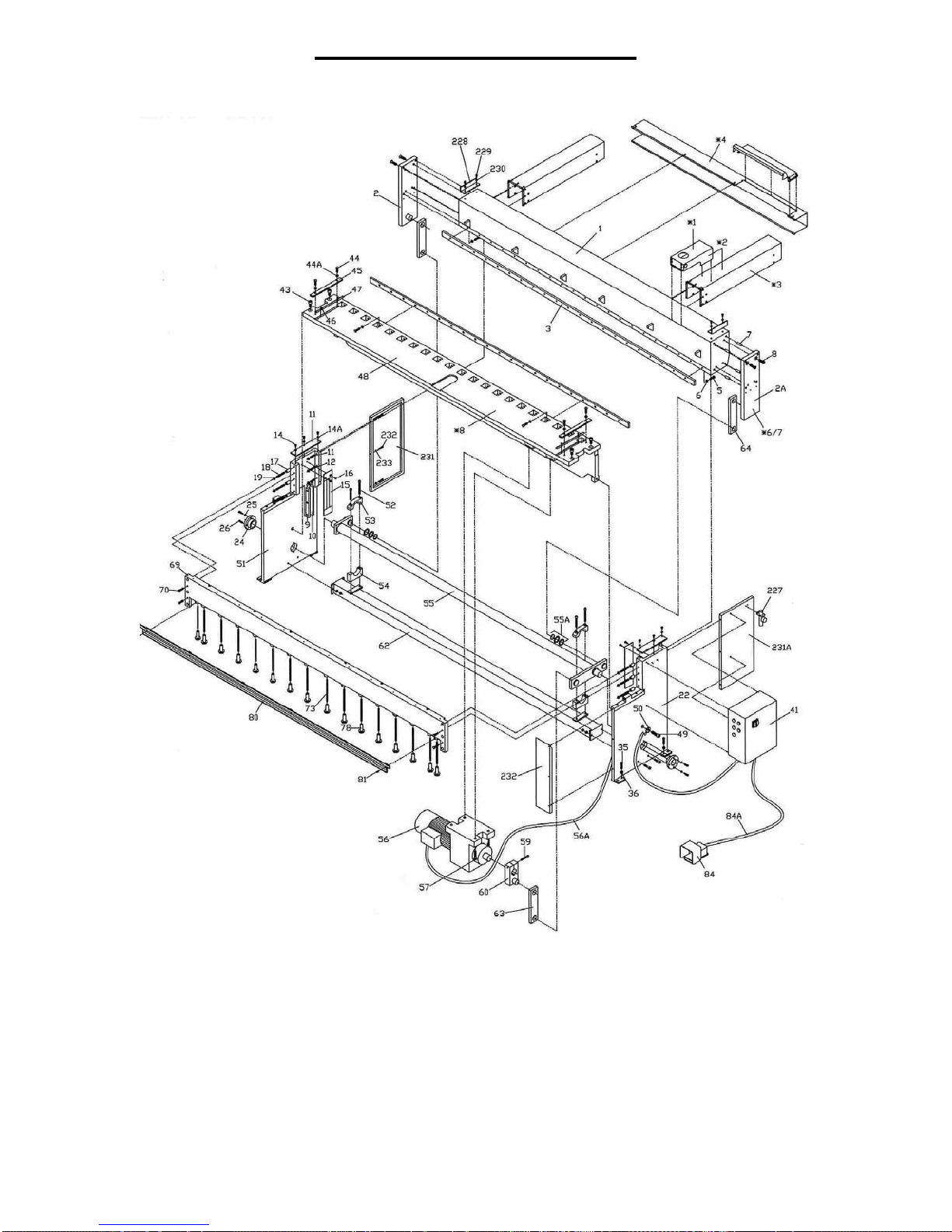
MODEL LM1010 PARTS LIST
ITEM# LM PART# DESCRIPTION QTY.
1 1010001 CUTTER HEAD 1
2L 101002L GIBB PLATE LEFT 1
2R 101002R GIBBPLATERIGHT 1
3 1010003 BLADE TOP & BOTTOM 2
4 1010004 SET SCREW, ROD MOUNTING 4
5 1010005 BOLT, BLADE MOUNTING 21
6 1010006 LOCK WASHER, BLADE 21
7 1010007 DOWEL PIN, GIBB PLATE 8
8 1010008 BOLT, GIBB PLATE 8
9 1010009 GIBB, CUTTER HEAD 2
10 1010010 BEARING MATERIAL, GIBB 4
11 1010011 TOP PLATE, SIDE PANEL 2
12 1010012 NUT, REAR GIBB ADJ. 6
13 1010013 SCREW, REAR GIBB ADJ. 6
14 1010014 BOLT, TOP PLATE SIDE PANEL 6
15 1010015 SPACER PLAET, SIDE PANEL 2
15A 101015A BEARING MATERIAL SPACER 4
16 1010016 BOLT, SPACER PLATE 4
17 1010017 SPACER SLEEVE, HOLD DOWN 6
18 1010018 SCREW, GIBB ADJ. FRONT 6
19 1010019 NUT, SCREW, GIBB ADJ. FRONT 6
20 1010020 BOLT, TABLE ADJ. 4
21 1010021 SCREW, CONTROL BOX MOUNT 4
22 1010022 SIDE PANEL, RIGHT 1
23 1010023 BUSHING, COLLAR 2
24 1010024 COLLAR, TREADEL MOUNT 2
25 1010025 LOCK WASHER, BOLT COLLAR 4
26 1010026 BOLT, COLLAR MOUNTING 4
27 1010027 ARM, SWITCH TRIP 1
28 1010028 BOLT, ARM MOUNTING SWITCH 1
29 1010029 PIN, ARM MOUNTING SWITCH 2
30 1010030 LOCK WASHER, BOLT, ARM MOUNTING 1
31 1010031 NUT, ADJUSTER, SWITCH TRIP 1
32 1010032 ADJUSTER, SWITCH TRIP 1
33 1010033 LIMIT SWITCH 1
34 1010034 SCREW, SWITCH MOUNTING 2
35 1010035 BOLT, LEVEL ADJUSTING 4
36 1010036 NUT, BOLT, LEVEL ADJUSTING 4
37 1010037 BOLT, SUPPORT BEAM MOUNTING 4
38 1010038 SCREW, COVER MOUNTING SWITCH 4
39 1010039 COVER, SWITCH 1
40 1010040 SCREW, SPACER PLATE MOUNTING, SIDE 4
41 1010041 ELECTRIC CONTROL BOX 1
42 1010042 SWITCH, FORWARD REVERSE 1
43 1010043 BOLT, TABLE MUNTING, TOP 4
44 1010044 BOLT, MATERIAL GUIDE BAR MOUNTING 4
45 1010045 MATERIAL GUIDE BAR 2
46 1010046 SCREW, SCALE MOUNTING, TABLE 2
47 1010047 SCALE, TOP 2
48 1010048 TABLE 1
49 1010049 BOLT, TABLE MOUNTING, ENDS 2
50 1010050 FLAT WASHER, BOLT, TABLE MOUNTING 2
51 1010051 SIDE PANEL, LEFT 1
52 1010052 BOLT, BEARING BLOCK MOUNTING 2
52A 101052A BOLT, BEARING BLOCK MOUNTING 2
53 1010053 BEARING BLOCK, UPPER 2
54 1010054 BEARING BLOCK, LOWER 2
55 1010055 DRIVE SHAFT 1
55A 101055A SPACER, SNAP RING, DRIVE SHAFT LINK 6
56 1010056 ELECTRIC GEAR MOTOR 1
57 1010057 BOLT, MOTOR AND GEAR BOX MOUNTING 4
58 1010058 KEY, SHAFT, GEAR BOX 1
59 1010059 BOLT, ARM AND PIN ASSEMBLY, GEAR BOX SHAFT 1
60 1010060 ARM AND PIN ASSEMBLY, GEAR BOX FRONT LINK 1
61 1010061 BEARING MATERIAL, BEARING BLOCK 2
62 1010062 SUPPORT BEAM 1
63 1010063 LINK, FRONT 1
64 1010064 LINK, REAR 2
65 1010065 REAR CHUTE 1
66 1010066 SCREW, REAR CHUTE MOUNTING 5
67 1010067 RETAINER RING, LINK MOUNTING 6
68 1010068 SPACER, LINK 12
69 1010069 HOLD DOWN 1
70 1010070 BOLT, HOLD DOWN MOUNTING 4
71 1010071 JACK SCREW, HOLD DOWN 6
72 1010072 NUT, STUD, FOOT MOUNTING, HOLD DOWN 16
73 1010073 STUD, FOOT MOUNTING, HOLD DOWN 16
74 1010074 BUSHING, QUILL, HOLD DOWN 16
75 1010075 FOOT, HOLD DOWN 16
76 1010076 RUBBER PAD, FOOT, HOLD DOWN 16
77 1010077 FINGER GUARD, HOOLD DOWN 1
78 1010078 SCREW, FINGER GUARD MOUNTING 6
79 1010079 FOOT SWITCH 1
79A 101079A CABLE, FOOT SWITCH 1

16
LM 2x Back gauge Crank Assembly

17
LM 2x Back gauge Crank Assembly Parts List
ITEM# LM PART# DESCRIPTION QTY.
83 20083 THRUSTWASHER 5
85 20085 LOCK WASHER, BOLT, SPROCKET MOUNTING 8
86 20086 SPACER RING, SPROCKET MOUNTING 4
87 20087 BEARING, SPROCKET MOUNTING 4
88 20088 SPROCKET 8
89 20089 CHAIN 1
102 20102 BOLT, SPROCKET AND SPACER BLOCK MOUNTING 3
103 20103 FLAT WASHER, BOLT, SPROCKET SPACER BLOCK 3
139 20139 SCREW, CRANK COVER MOUNTING 4
140 20140 LOCK WASHER, CRANK COVER MOUNTING 4
146 20146 STRIPPER BOLT, IDLER SPROCKET MOUNTING 3
147 20147 BEARING, IDLER SPROCKET 3
148 20148 IDLER SPROCKET 3
150 20150 NUT, STRIPPER BOLT, IDLER SPROCKET 3
151 20151 BOLT, IDLER SPROCKET BRACKET MOUNTING 12
152 20151 LOCK WASHER, BOLT, IDLER SPROCKET BRACKET 12
153 20153 BRACKET, IDLER SPROCKET MOUNTING 1
174 20174 BOLT, HANDLE MOUNTING 1
175 20175 HANDLE, CRANK 1
176 20176 CRANK 1
177 20177 NUT, BOLT, HANDLE MOUNTING 1
178 20178 SCREW, CRANK MOUNTING 4
179 20179 COVER, CRANK 1
180 20180 ACEME NUT, LOCK HANDLE 2
181 20181 NUT, LOCK HANDLE 1
182 20182 LOCK, CRANK BLOCK 1
183 20183 STUD, LOCK HANDLE 1
184 20184 SPACER, LOCK HANDLE 1
185 20185 NUT, LOCK HANDLE MOUNTING 1
186 20186 HANDLE, LOCK MOUNTING 1
187 20187 SPRING, LOCK HANDLE MOUNTING 1
188 20188 SCREW, HANDLE MOUNTING 1
189 20189 SPACER, SPROCKET MOUNTING 1
190 20190 SCREW, SPROCKET MOUNTING 4
191 20191 SPACER, SET SCREW 1
192 20192 SET SCREW 1
193 20193 STUD, LOCK MOUNTING 1
194 20194 SPACER, STUD 1
195 20195 BRACKET, IDLER SPROCKET BRACKET MOUNTING 1

18
LM 2x Back gauge Pointer Assembly
LM 2x Back gauge Pointer Assembly Parts List
ITEM# LM PART# DESCRIPTION QTY.
136 20136 COVER, SCALE POINTER ASSEMBLY 1
137A 2137A SCALE, INCH/METRIC 30 ICHES 1
138 20138 SCREW, SCALE BRACKET AND COVER MOUNTING 3
139 20139 LOCK WASHER, SCREW, SCALE BRACKET 3
140 20140 BRACKET, SCALE MOUNTING 1
141 20141 BRACKET, ROD MOUNTING 2
142 20142 SET SCREW, ROD MOUTNING 2
143 20143 BOLT, BRACKET MOUNTING 2
144 20144 LOCK WASHER, BOLT, BRACKET MOUNTING 2
145 20145 CHAIN 1
146 20146 STRIPPER BOLT, IDLER SPROCKET MOUNTING 3
147 20147 BEARING, IDLER SPROCKET 3
148 20148 IDLER SPROCKET 3
150 20150 NUT, STRIPPER BOLT, IDLER SPROCKET 3
151 20151 BOLT, IDLER SPROCKET BRACKET MOUNTING 12
152 20151 LOCK WASHER, BOLT, IDLER SPROCKET BRACKET 12
153 20153 BRACKET, IDLER SPROCKET MOUNTING 1
154 20154 BRACKET, IDLER SPROCKET BRACKET 1
155 20155 BLOCK, POINTER MOUNTING 1
156 20156 RETAINER, BEARING MOUNTING 2
157 20157 TEFLON PIN, POINTER BLOCK 2
158 20158 SPRING, POINTER BLOCK 2
159 20159 SET SCREW, POINTER BLOCK 2

19
LM 2x Back gauge Pointer Assembly Parts List
ITEM# LM PART# DESCRIPTION QTY.
160 20160 NUT, SET SCREW, POINTER BLOCK 2
161 20161 CLAMP, CHAIN LOCK, POINTER BLOCK 1
162 20162 BOLT, CLAMP MOUNTING, POINTER BLOCK 2
163 20163 BEARING, POINTER BLOCK 1
164 20164 SCREW, POINTER MOUNTING 2
165 20165 POINTER, SCALE 1
LM 2x Back gauge Drive Assembly Parts List
ITEM# LM PART# DESCRIPTION QTY.
81 20081 BOLT, BRACE MOUNTING 2
82 20082 LOCK WASHER, BOLT, BRACE MOUNTING 2
83 20083 THRUSTWASHER 5
84 20084 BOLT, SPROCKER MOUNTING 8
85 20085 LOCK WASHER, BOLT, SPROCKET MOUNTING 8
129 20129 LOCK WASHER, BOLT, SPROCKET MOUNTING 8
86 20086 SPACER RING, SPROCKET MOUNTING 4
87 20087 BEARING, SPROCKET MOUNTING 4
88 20088 SPROCKET 8
89 20089 CHAIN 1
90 20090 SPACER BLOCK, SPROCKET AND CRANK MOUNTING 1
91 20091 CHAIN 1
92 20092 SPACER RING, SPROCKET MOUNTING 3
93 20093 SHAFT, SPACER BLOCK AND SPROCKET MOUNTING 1
95 20095 SUPPORT BLOCK, FRONT 2
125 20125 SHAFT, SPROCKET ASSEMBLY MOUNTING LEFT 1
Table of contents
Other Tennsmith Power Tools manuals