Tenor Audio 75Wi User manual

Tenor Audio 75Wi
Owner’s manual
Version 1.0

Table of contents
1 Safety Instructions
2 Introduction
3 Unpacking & Installation
4 Operation & Hook-up
5 Bias & DC-Balance adjustments
6 Specifications
7 Warranty
1
Safety Instructions
Save these instructions for later use. Follow all instructions and warnings marked on the unit.
Always use with the correct line voltage. Refer to the manufacturer's operating instructions for power requirements.
Be advised that different operating voltages may require the use of a different line cord and/or attachment plug.
Do not install the unit in an unventilated rack, or directly above heat producing equipment. Observe the maximum
ambient operating temperature listed in the product specification.
Slots and opening on the case are provided for ventilation; to ensure reliable operation and prevent it from
overheating, these openings must not be blocked or covered. Never push objects of any kind through any of the
ventilation slots. Never spill a liquid of any kind on the unit.
Never attach audio power amplifier outputs directly to any of the unit's connectors.
To prevent shock or fire hazard, do not expose the unit to rain or moisture, or operate it where it will be exposed to
water or excessive dampness. Do not remove vacuum tubes without unplugging power cord from AC mains.
Do not attempt to operate the unit if it has been dropped, damaged, exposed to liquids, or if it exhibits a distinct change
in performance indicating the need for service.
Caution!
Only qualified service personnel should open this unit. Removing covers will expose you to hazardous
voltages.
This triangle, which appears on your component,
alerts you to the presence of uninsulated
dangerous voltage inside the enclosure...voltage
that may be sufficient to constitute a risk of shock.
This triangle, which appears on your
component, alerts you to important operating
and maintenance instructions in this
accompanying literature.
Adhere to all warnings on the unit and in the operating instructions.
Take precautions not to defeat the grounding or polarization of the unit's power cord.
Do not overload wall outlet, extension cords or integral convenience receptacles, as this can result in a risk of fire or
electrical shock.
Route power supply cords so that they are not likely to be walked on or pinched by items placed on or against them,
paying particular attention to cords at plugs, convenience receptacles, and the point at which they exit from the unit.
The unit should be cleaned only as recommended by the manufacturer.
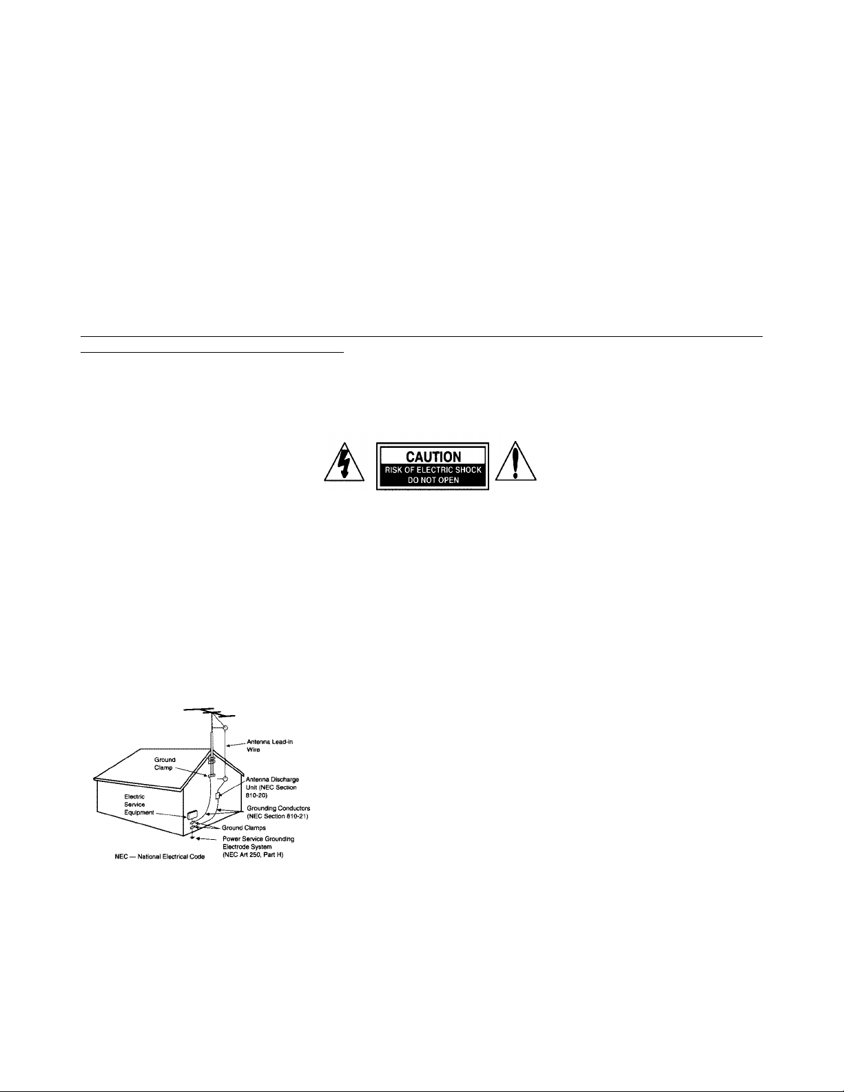
Outdoor Antenna Grounding
If an outside antenna is connected to the playback system, be sure the
antenna system is grounded so as to provide some protection against
voltage surges and built-up static charges. Section 810 of the National
Electrical Code, ANSI/NFPA No. 70-1984, provides information with
respect to proper grounding of the mast and supporting structure,
grounding of the lead-in wire to an antenna-discharge unit, size of
grounding conductors, location of antenna-discharge unit, connection to
grounding electrodes, and requirements for the grounding electrode.
See figure.
Note to CATV installers: Article 820-40 of the NEC provides guidelines for proper grounding and, in particular,
specifies that the cable ground shall be connected to the grounding system of the building, as close to the point of
cable entry as practical.
Power Lines: An outside antenna should be located away from power lines.

2
Introduction
Thank you for purchasing a Tenor Audio product. Please read this manual carefully in
order to ensure years of listening pleasure from these carefully designed and crafted
amplifiers. Keep this manual for future reference.
Tenor Audio tube amplifiers belong to a very special class recognized by many
audiophiles as the path to ultimate audio amplification. It is called Output Transformer
Less (OTL) and achieves unrivaled levels of transparency, clarity and speed by
avoiding all known limitations of even the best output transformers available. Our
amplifiers are the result of a three-year research program and push the OTL
performance envelope to unheard levels of musical refinement.
Dynamics
All our amplifiers have an impressive dynamic power reserve. Thus, they can
momentarily quadruple the rated output power without any perceived signal
degradation.
Stability
With two oversized power transformers and ten high performance regulated power
supplies, Tenor Audio amplifiers are immune to AC main voltage fluctuations, power
demand and speaker load reactance variations.
Harmonic Structural Integrity
No technical white paper can fully describe how our amplifiers preserve the music's
natural Harmonic Structural Integrity (HSI). Our complex yet refined circuits are based
on a balanced design of high performance triodes, high voltage regulation, two gain
stages, and a capacitor-less / transformer-less output stage. The HSI concept can
only be experienced when music reproduction is as satisfying as live music.

3
Unpacking your new amplifier
Each amplifier weighs XX pounds and the center of gravity is located in front of the
transformer housings.
Grab a firm hold of the amplifier chassis at the center of gravity and lift out of the crate.
Help might be advisable because of the physical weight of the amplifier.
Carefully remove the protective linings.
Inspect the equipment for visible signs of shipping damage.
Make sure that all the tubes and accessories are included. See the list below.
Tip: It may be preferable to install the tubes once the amplifier is securely installed in
its permanent location.
List of included tubes and accessories per pair:
•8 x 6C33 output tubes
•4 x 6H6P vacuum tubes
•4 x 6H30P vacuum tubes
•4 x 12AX7A / ECC83 vacuum tubes
•2 Power cords
•1 Adjustment screwdriver
•1 Hex key
•1 Owners manual
•2 Spare fan air filters
•2 Spare mains AC fuses
•2 Spare 5A 5mm fuses
Installation
The amplifier must be installed on a firm surface allowing adequate ventilation.
Do not attempt to operate the unit on a soft surface (i.e. carpet) where the ventilation openings
located on the bottom plate could be partially or totally blocked. Keep the unit away from sources of
heat or humidity (moisture). Do not stack.
Do not cover or install the unit in an unventilated enclosure. A clearance of 4 inches (10.0 cm)
allowed at the rear of the amplifier to reduce strain on the power cord.
A minimum space of 3/4 inches (2.0 cm) is necessary between the bottom plate of the amplifier and
the surface on which the amplifier is installed to allow proper convection cooling. The amplifier must
always rest on its feet.

4
Operation and Hook-up
To ensure maximum performance, use high quality interconnect and speaker cables with proper
termination. All interconnects from source components and speaker cables should be of equal
length.
Operation
Each amplifier has a selectable single ended or balanced input.
Note: The amplifier must always be muted before changing input mode.
Only one (1) interconnect cable, single-ended or balanced. may be
connected at one time. Severe damage to the amplifier may occur.
Mute: Mute function is active when the front panel’s lens lit red.
Clipping:
Source Components
Hook up the left channel output of the individual source component (CD player, Tuner, etc…) to the
left amplifier (white RCA connector) that will drive the left loudspeaker and the right channel output
of the source device to the corresponding input on the right amplifier (red RCA connector) driving
the right loudspeaker.
Speakers
Connect the speaker making sure to respect polarity: the positive (+) output should be connected to
the positive speaker connector (labeled generally “+” or red color connector) and the negative output
(-) to the negative connector of the loudspeaker (labeled “-“ or white connector).
Notes: Speaker output terminals are “floating” outputs, they must never be grounded or in contact
with the metal chassis.
Do not connect AC mains power cord at this point! Before powering up the amplifiers for the
first time, you need to make a number of initial adjustments as described in the next section.
CAUTION: Do not attempt to use the amplifiers before making these initial adjustments!

5
Bias current and DC-Balance pre-adjustment procedure
Ensure the AC power cord is disconnected from the unit and the power switch set to the “off”
position: lower half of switch recessed.
Verify that the fan’s air filter is properly installed (bottom chassis plate).
Install tubes as indicated on the bottom chassis plate. The location numbers are marked on each
tube. ( i.e.: V8L or V8R ). Note that the tubes are matched for the left and right amplifier individually.
( Right = Red RCA, Left = White RCA ).
Ensure the speakers are connected to the output terminals.
Set the amplifier to mute.
Set the DC-Bal. control (left knob on the top of the unit) to “Ref” or 12 o’clock position.
With a small screwdriver, adjust V7 and V8 bias control potentiometer (located below the left rotary
dc balanced knob) to the middle of the adjustment range.
Repeat with V9 and V10 (located below the right rotary bias knob).
Connect AC power cord, audio interconnects, then set the power switch to “on” (top half recessed)
and run the unit for 30 minutes. The power indicator light will change from red to green indicating the
end of the one minute soft start cycle.
BIAS and DC-BALANCE adjustments
Note: the onboard meter is operational in mute mode only.
1. Ensure that the amplifier is in mute.
2. Set the bias rotary selector to V7 and with a small screwdriver adjust slowly V7 bias
potentiometer to read +300mA on the meter. The normal operating bias current for each
6C33C-B power tube is +300mA;the meter range is 0 to +500mA.
3. Set the bias rotary selector to successively V8-V9-V10 and perform the same adjustment as
step 2 above.
4. Repeat steps 2 and 3 until V7, V8,V9 & v10 read 300mA. Because of the specific nature of the
6C33C-B power triode, this may take some repeating.
5. Set the Bias rotary selector to DC-Bal. and read the DC imbalance on the meter. If step 4 was
precisely executed the DC imbalance should be less than +/- 50mV.
6. Turn the DC-Bal. control knob slowly (left knob on the top of the unit) in order to read zero mV
on the meter. The meter range in this mode is +/- 250mV.
7. Set the bias rotary selector to off.
8. After 2 or 3 hours of listening, check the meter readings and readjust if necessary.
ADDITIONAL IMPORTANT NOTES
During the first 50 hours of operation, it may be necessary to periodically check and adjust the bias
current and the DC-Balance after 2 to 3 hours of operation. The 6C33C-B tube takes approximately
50 hours to completely stabilize. After this initial period, the amplifier will remain stable (less than+/-
5mV imbalance) even for long periods of time. To obtain maximum tube life and ensure optimal
performance, a monthly check is recommended.
Although Tenor amplifiers are exceptionally stable on low impedance loads, speakers with difficult or
reactive loads below 4 Ohms will require the output stage to deliver more than twice the normal
current and consequently risk to overload and damage the output tubes.

6
Specifications
Amplifier type Mono Power amplifier
Rated power: 4, 8, 16 Ohms 60, 75, 75 W
Load impedance 4 – 16 Ohms
Recommended load 8 Ohms
Dynamic power: 8 Ohms 225 W
Pure Class A power: 8 Ohms 40 W
Power Bandwidth (-3 dB) 2 to 160 000 Hz
Harmonic distortion + noise less than 0,5%
Intermodulation distortion less than 0,5%
Signal to noise ratio 100 dB A weighted
Input impedance 40 K Ohms
Output impedance 0.4 Ohms
Input sensitivity 350 mV bal., 700 mV RCA.
Output stage power transformer 750 VA
Driver stage power transformer 750 VA
Input RCA or XLR
Multi function meter analog 1.5 %
Input tubes 2 x 12AX7A, 2 x 6H6P , 2 x 6H30P
Output tubes 4 x 6C33C-B
Soft start / Mute 1 minute
Maximum power consumption 730 W
Supply voltage 100, 120, 220 or 240
AC mains input 15 / 6A IEC detachable power cord
Dimensions ( w x d x h ) 17.25 x 23 x 11 inches
Weight per unit 71 pounds

7
WARRANTY
THREE YEARS LIMITED WARRANTY
PROOF OF PURCHASE REQUIRED
Tenor Audio warrants the product referred to in this manual to be free from defects in materials or
workmanship, for a period of three (3) years from the date of the original purchase. This warranty
does not include liability for damage resulting from accident, misuse, abuse, alteration, improper
connection or incorrect line voltage. This warranty is limited to the original purchaser and to the 2nd
owner only.
Vacuum tubes are guaranteed for a period of three months after purchase.
Should the unit become defective during the warranty period, Tenor Audio will elect to repair or
replace the unit free of charge.
Tenor Audio will NOT accept packages without prior authorization, original wood crates, pre-paid
freight and proper insurance.
Please call 514-938–5556 for a return authorization number.
THE USE OF TUBES NOT SUPPLIED BY TENOR AUDIO WILL VOID THE WARRANTY.
ATTEMPTING TO REPAIR OR MODIFY UNIT IS NOT RECOMMENDED AND WILL VOID
WARRANTY.
MISSING OR ALTERED SERIAL NUMBERS AUTOMATICALLY VOID WARRANTY.
Tenor Audio Inc
1001 Lenoir Suite A-205
Montreal PQ
Canada, H4C 2Z6
Phone: 514 938 5556
Fax : 514 938 4567
www.tenoraudio.com
Table of contents
Other Tenor Audio Amplifier manuals


