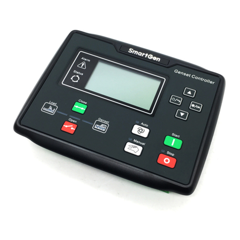
Tense TDK-96 User manual

ELEKTRİK - ELEKTRONİK SAN.TİC.A.Ş.
TDK-96 and TDK-96H
SUBMERSIBLE PUMP
CONTROL RELAY
USER MANUAL
www.tense.com.tr
Work without
Electrode
Number of
Stop/Start
Total Working
Hours
TR/EN
Menu Language
Energy
Meter
Error
Logs

Device Maintenance
Index
1
1
1
About Device
12-13
13-15
19-20
20
21
21
18
18
18
Advanced Setting Menu
Expert Setting Menu
Factory Values
Star-Delta Operation Characteristic
Dimensions
Technical Specifications
Well Control
Tank Control
17
Demurrage Current Control
16
Voltage Asymmetry
16
Current Asymmetry
16
Changing the Password to Enter the Menu
15
Alarm Relay Assigment
17
Electrodeless Well Control
Connection Diagram 3
4
4
5-7
8-9
10-11
Measurement Screens
Menu Screens
Current Menu
Voltage Menu
Electrode Menu
Considerations in Current Transformer Connection
Introduction of Screen and Buttons
2
2
2
Specifications
External Start Stop Control
Warnings

Easy Installation and Operation with 2.9”(128x64) Graphic LCD
Remote Communication with RS485 (Modbus RTU) (Only in models with communication)
Easy to Use Menu
Turkish and English Language Option
Voltage (V), Current (A) and Cosine (Cos) can be Monitored on the Same Screen
Active Power (P), Apparent Power (S) and Cosine (Cos) can be Monitored on the Same Screen
Total Active Energy (Σ+P) can be Monitored
High and Low Cosine Set Value Adjustable
High and Low Voltage Set Value Adjustable
High and Low Current Set Value Adjustable
Voltage Asymmetry Set Value Adjustable
Current Asymmetry Set Value Adjustable
Well Upper Electrode Waiting Time Adjustable
Tank Upper Electrode Waiting Time Adjustable
Liquid Sensitivity Adjustable
Error Logs (9999 records for each event)
Star-Delta Contact Output
Phase Sequence Protection Adjustable
Start/Stop Memory (Operating from the last position)
Notifies Pump Maintenance Time
Manual, Semi-Automatic and Fully Automatic Reset Mode
External Start/Stop Input
1x Adjustable Alarm Output
Electrodeless Well Control
The Number of Pump Starts/Stops and the Total Working Time can be Monitored
Specifications
About Device
Submersible pump control relays are designed to control submersible pumps and motors
used in wells and similar places, and to protect them from adverse situations that may arise
from waterless operation, high or low voltage and current.
Device Maintenance
Power off the device and disconnect it from the connections. Clean the body of the device
with a slightly damp or dry cloth. Do not use conductive or other chemicals that may damage
the device as a cleaning agent. After cleaning the device, make the connections and make sure
that the device is energized and working.
1

Warnings
Use the device in accordance with the instructions given by us.
In order not to damage the LCD screen, be careful not to get direct sunlight.
After the device is mounted, leave a space of at least 10 cm behind it.
Fix the device to the front cover of the panel with the apparatus in the box.
Regulate the indoor and outdoor temperature so that there is no condensation on the metal
panels. This situation is dangerous for open connection busbars.
Keep the switch and circuit breaker close to the device and within easy reach of the operator.
Mark the switch and circuit breaker as disconnection element for the device.
Include a switch or circuit breaker in the installation.
There should be no electricity in the connecting cables during assembly.
Shielded and twisted cord cable should be used for input and output lines that are not connected to
the mains. These cables should not be passed near high power lines and devices.
Do not apply energy to the electrode (well and tank) and start-stop inputs.
Considerations in Current Transformer Connection
Current transformer outputs and phase inputs must be in the same order. Connect the
k-l terminals of the current transformer connected to the L1 phase to the k1-l1 terminals,
the k-l terminals of the current transformer connected to the L2 phase to the k2-l2 terminals
and the k-l terminals of the current transformer connected to the L3 phase to the k3-l3 terminals.
Pass the current transformer output cables away from the high voltage line.
Fix it to the busbar, cable or rail so that the current transformers are not shaken.
2
Introduction of Screen and Buttons
1
2
3
1- Graphic LCD: It is the screen where all measurements, settings and
notifications about the device are transferred to the user.
2- Button Function Definition: The buttons on the device are defined for
more than one function. The button functions that appear at the bottom of
the screen are divided into four separate buttons as F1, F2, F3 and F4. For
example, if SET is written above the F2 function, it will enter the setting
menu when you press the F2 button.
3- Buttons: The functions of the buttons are associated with the definitions
that appear on the screen. Button functions are described below.
RESET Button: It enables the device to be reset when the device is in error.
START Button: It takes the device in the start position and starts the pump.
STOP Button: It takes the device in the stop position and stops the pump.
ESC Button: Returns to the upper menu without saving the changed value while in the menu.
SET Button: Enters menu, submenu and parameter. Exits the parameter by saving the change in the parameter.
UP Button: Allows to move through the sub-menus in the menu. Increases the selected value while in the parameters.
DOWN Button: It enables to move between the measured values outside the menu. Allows to move through the sub-
menus in the menu. Decreases the selected value while in the parameters.
RIGHT Button: Allows you to switch between the password steps on the password screen to enter the menu.

3
Connection Diagram
Neutr.
(N)
Alarm Signal
Lamp
N
U1U2
V1V2
W1W2
PHASE
MAIN
STAR
DELTA
ALARM
External Control
Do not apply energy to the electrode
(well and tank) and start-stop inputs.
!
TANK
Upper
Bottom
Lower
WELL
Upper
Bottom
Lower
Start Button
Stop Button
Common
Start
Input
Stop
Input

Measurement Screens
Voltage Current
L12: 380V I1: 10.1A
L23: 380V I2: 100A
L31: 380V I3: 1000A
r:0.99 s:0.99 t:0.99
Reset Set Stop Down
_____________________
Active(P) Apparent(S)
L1:0.800kW 0.800kVA
L2:38.00kW 10.00kVA
L3:380.0kW 100.0kVA
r:0.99 s:0.99 t:0.99
Reset Set Stop Down
_____________________
DOWN
SET
DOWN
Active Energy(+²P)
L1: 0123456789.123kWh
L2: 0123456789.123kWh
L3: 0123456789.123kWh
T : 01234567890123kWh
_____________________
Reset Set Stop Down
DOWNDOWN
Figure-1 Figure-2 Figure-3
Infos :
Status : Start
Well Level : Middle
Tank Level : Full
_____________________
Reset Set Stop Down
DOWN
Errors :
Cosine :High
Voltage :High
Phase seq :True
Current :Low
_____________________
Reset Set Stop Down
Figure-4Figure-5
Figure-1: Phase-phase voltage values, phase-neutral current values and cosine values of
each phase are displayed on the screen.
Figure-2: Active power values, apparent power values and cosine values of each phase are
displayed on the screen.
Figure-3: The total active (export) energy values of each phase are displayed on the screen.
Figure-4: Device status (Start/Stop) and well and tank level (full/medium/empty) are displayed
on the screen.
Figure-5: Error conditions (true/reverse for high/low phase sequence for voltage, current and
cosine values) are displayed on the screen.
Enter Password !
0000
_
Esc Set Up Right
_____________________
Menu Screens
Voltage Current
L12: 380V I1: 10.1A
L23: 380V I2: 100A
L31: 380V I3: 1000A
r:0.99 s:0.99 t:0.99
Reset Set Stop Down
_____________________
Figure-1 Figure-2
Figure-3Figure-7 Figure-4
Figure-6 Figure-5
Menu 1.0
CURRENT MENU
Esc Set Up Down
_____________________
SET
Esc Set Up Down
Menu 2.0
VOLTAGE MENU
_____________________
DOWN
UP
DOWN
UP
Esc Set Up Down
Menu 3.0
ELECTRODE MENU
_____________________
UP
DOWN
Esc Set Up Down
Menu 4.0
ADVANCED SETTING MENU
_____________________ DOWN
UP
Esc Set Up Down
Menu 5.0
EXPERT SETTING MENU
_____________________
UP
DOWN
ESC
4

5
Entering Settings: When the SET button is pressed while on any measurement page, the
PASSWORD page (Figure-2) is displayed to enter the menu.
While on this page, press the SET button to enter the menu.
(The password value is "0000" by default. If the password has been changed by the user, the
password specified by the user must be used to enter the menu.)
For password entry, you can switch between the steps with the RIGHT button. You can change
the value of the digit with the UP button.
If no button is pressed for 30 seconds in the menu, the device returns to the main screen.
CURRENT MENU (Menu 1.0): It is the first menu that appears when you proceed by pressing
the UP button after entering the settings menu (Figure-3). In this menu, high/low current set
values, error delays, automatic reset delays, automatic reset numbers, demurrage multiplier
and demurrage time and current asymmetry set value settings can be set.
VOLTAGE MENU (Menu 2.0): It is the second menu that appears when you proceed by pressing
the UP button after entering the settings menu (Figure-4). In this menu, high/low voltage set
values, error delays, automatic reset delays, voltage asymmetry set value and phase sequence
protection feature set value settings can be set.
ELECTRODE MENU (Menu 3.0): It is the third menu that appears when you proceed by pressing
the UP button after entering the settings menu (Figure-5). In this menu, electrode set value,
well and tank electrode reading values, electrode delay times, high/low cosine set values,
cosine automatic reset delays set value settings can be set.
ADVANCED SETTING MENU (Menu 4.0): It is the fourth menu that appears when you proceed
by pressing the UP button after entering the settings menu (Figure-6). In this menu, starting
time, Modbus RTU communication settings, start/stop memory, star waiting time, panel
control feature, alarm relay assignment set value settings can be set.
EXPERT SETTING MENU (Menu 5.0): It is the fifth menu that appears when you proceed by
pressing the UP button after entering the settings menu (Figure-7). In this menu, engine
operation information, voltage, current and cosine error records can be displayed. Factory
values can be restored, menu language and password values and screen light off time set
value settings can be set.
Settings E Current Menu
It is the first menu that appears after you enter the settings
menu. In this menu, high/low current set values, error delays,
automatic reset delays, automatic reset numbers, demurrage
multiplier and demurrage time and current asymmetry set
value settings can be set.
To enter the Current Menu, press the SET button while the
Current Menu page is on the screen. Use UP and DOWN
buttons to access other settings in the menu.
AKIM TRAFO
Menu.1.0
MENUSU
Menu 1.0
CURRENT MENU
Esc Set Up Down
_____________________
Menu 1.1
High Current Set
50.0A
_____________________
Esc Set Up Down
It determines the maximum operating current (overload) of
the pump.
To change this value, press the SET button while the High
Current Set page is on the screen. “Menu 1.1.0” will appear
on the screen. Enter the new value to the device using the UP
and DOWN buttons and press the SET button to save.
Settings E Current Menu E High Current Set Value

6
Menu 1.5
Low Current Set
OFF
_____________________
Esc Set Up Down
Menu 1.4
High Current Auto
Reset Number
OFF
_____________________
Esc Set Up Down
Menu 1.3
High Curren Auto
Reset Delay
OFF
_____________________
Esc Set Up Down
Menu 1.2
High Current Error
Entrance Delay
5 Sc.
_____________________
Esc Set Up Down
It determines the time the device will wait before stopping
the pump when it enters a high current error.
To change this value, press the SET button while the High
Current Error Entrance Delay page is on the screen. “Menu
1.2.0” will appear on the screen. Enter the new value to the
device using the UP and DOWN buttons and press the SET
button to save.
It determines the time the device will wait for the pump to
restart (reset) after entering a high current error.
To change this value, press the SET button while the High
Current Auto Reset Delay page is on the screen. “Menu
1.3.0” will appear on the screen. Enter the new value to the
device using the UP and DOWN buttons and press the SET
button to save.
It determines how many times the pump will be restarted
automatically after the device enters a high current error.
To change this value, press the SET button while the High
Current Automatic Reset Number page is on the screen.
“Menu 1.4.0” will appear on the screen. Enter the new value
to the device using the UP and DOWN buttons and press the
SET button to save.
Settings E Current Menu E High Current Auto Reset Number
It determines the minimum operating current of the
pump.
To change this value, press the SET button while the Low
Current Set page is on the screen. “Menu 1.5.0” will appear
on the screen. Enter the new value to the device using the
UP and DOWN buttons and press the SET button to save.
Settings E Current Menu E Low Current Set Value
Menu 1.6
Low Current Error
Entrance Delay
5 Sc.
_____________________
Esc Set Up Down
It determines the time the device will wait before stopping
the pump when it enters a low current error.
To change this value, press the SET button while the Low
Current Error Entrance Delay page is on the screen. “Menu
1.6.0” will appear on the screen. Enter the new value to the
device using the UP and DOWN buttons and press the SET
button to save.
Settings E Current Menu E Low Current Error Entrance Delay
Settings E Current Menu E High Current Error Entrance Delay
Settings E Current Menu E High Current Auto Reset Delay

7
Menu 1.10
Demurrage Time
10 Sc.
_____________________
Esc Set Up Down
Menu 1.9
Demurrage Multiplier
2.0 10.0A
_____________________
Esc Set Up Down
Menu 1.8
Low Current Auto
Reset Number
OFF
_____________________
Esc Set Up Down
Menu 1.7
Low Current Auto
Reset Delay
OFF
_____________________
Esc Set Up Down
It determines the time the device will wait for the pump to
restart (reset) after entering a low current error.
To change this value, press the SET button while the Low
Current Auto Reset Delay page is on the screen. “Menu
1.7.0” will appear on the screen. Enter the new value to the
device using the UP and DOWN buttons and press the SET
button to save.
Settings E Current Menu E Low Current Auto Reset Delay
It determines how many times the pump will be restarted
automatically after the device enters a low current error.
To change this value, press the SET button while the Low
Current Automatic Reset Number page is on the screen.
“Menu 1.8.0” will appear on the screen. Enter the new value
to the device using the UP and DOWN buttons and press the
SET button to save.
It determines the maximum current that the pump
connected to the device can draw in demurrage (start-up).
(Demurrage current = Demurrage Multiplier x High Current
Set Value) (The value on the left of the screen represents the
demurrage multiplier, and the value on the right represents
the demurrage current.)
If the pump draws current above this value while in
demurrage, the device stops the pump without waiting.
Settings E Current Menu E High Current Auto Reset Number
Settings E Current Menu E Demurrage Multiplier
To change this value, press the SET button while the Demurrage Multiplier page is on the
screen. “Menu 1.9.0” will appear on the screen. Enter the new value to the device using the UP
and DOWN buttons and press the SET button to save.
It determines the time until the pump returns to the
normal current level after each energization.
To change this value, press the SET button while the
Demurrage Time page is on the screen. “Menu 1.10.0” will
appear on the screen. Enter the new value to the device using
the UP and DOWN buttons and press the SET button to save.
Settings E Current Menu E Demurrage Time
Menu 1.11
Current Asymmetry Set
50 %
_____________________
Esc Set Up Down
It determines the percentage of the maximum difference
that will occur between the currents drawn by the pump.
To change this value, press the SET button while the Current
Asymmetry Set page is on the screen. “Menu 1.11.0” will
appear on the screen. Enter the new value to the device using
the UP and DOWN buttons and press the SET button to save.
Settings E Current Menu E Current Asymmetry Set Value

8
Menu 2.3
High Voltage Auto
Reset Delay
OFF
Esc Set Up Down
_____________________
Menu 2.2
High Voltage Error
Entrance Delay
5 Sc.
Esc Set Up Down
_____________________
Menu 2.1
High Voltage Set
420 V
Esc Set Up Down
_____________________
Menu 2.0
VOLTAGE MENU
Esc Set Up Down
_____________________
Settings E Voltage Menu
It is the second menu that appears after you enter the
settings page. In this menu, high/low voltage set values, error
delays, automatic reset delays, voltage asymmetry set value
and phase sequence active/passive set value settings can be
set.
To enter the Voltage Menu, press the SET button while the
Voltage Menu page is on the screen. Use UP and DOWN
buttons to access other settings in the menu.
Settings E Voltage Menu E High Voltage Set Value
It determines the maximum operating voltage (phase-phase)
of the pump
To change this value, press the SET button while the High
Voltage Set page is on the screen. “Menu 2.1.0” will appear on
the screen. Enter the new value to the device using the UP and
DOWN buttons and press the SET button to save.
Settings E Voltage Menu E High Voltage Error Entrance Delay
It determines the time the device will wait before stopping
the pump when it enters a high voltage error.
To change this value, press the SET button while the High
Voltage Error Entrance Delay page is on the screen. “Menu
2.2.0” will appear on the screen. Enter the new value to the
device using the UP and DOWN buttons and press the SET
button to save.
It determines the time the device will wait for the pump to
restart (reset) after entering a high voltage error. This
feature is activated when all voltages fall below 10V of the
High Voltage Set Value.
To change this value, press the SET button while the High
Voltage Auto Reset Delay page is on the screen. “Menu 2.3.0”
will appear on the screen. Enter the new value to the device
using the UP and DOWN buttons and press the SET button to
save.
Settings E Voltage Menu E High Voltage Auto Reset Delay
Menu 2.4
Low Voltage Set
330 V
Esc Set Up Down
_____________________
Settings E Voltage Menu E Low Voltage Set Value
It determines the minimum operating voltage (phase-phase)
of the pump
To change this value, press the SET button while the Low
Voltage Set page is on the screen. “Menu 2.4.0” will appear on
the screen. Enter the new value to the device using the UP and
DOWN buttons and press the SET button to save.

Menu 2.8
Phase Seq. On / Off
On : Active
Esc Set Up Down
_____________________
Menu 2.7
Voltage Asymmetry Set
20 %
Esc Set Up Down
_____________________
Menu 2.6
Low Voltage Auto
Reset Delay
OFF
Esc Set Up Down
_____________________
Menu 2.5
Low Voltage Error
Entrance Delay
5 Sc.
Esc Set Up Down
_____________________
Settings E Voltage Menu E Low Voltage Error Entrance Delay
It determines the time the device will wait before stopping the
pump when it enters a low voltage error.
To change this value, press the SET button while the Low
Voltage Error Entrance Delay page is on the screen. “Menu
2.5.0” will appear on the screen. Enter the new value to the
device using the UP and DOWN buttons and press the SET
button to save.
It determines the time the device will wait for the pump to
restart (reset) after entering a low voltage error. This
feature is activated when all voltages rise above 10V above
the Low Voltage Set Value.
To change this value, press the SET button while the Low
Voltage Auto Reset Delay page is on the screen. “Menu
2.6.0” will appear on the screen. Enter the new value to the
device using the UP and DOWN buttons and press the SET
button to save.
Settings E Voltage Menu E Low Voltage Auto Reset Delay
It determines the percentage of the maximum voltage
difference that will occur between the phases.
To change this value, press the SET button while the Voltage
Asymmetry Set page is on the screen. “Menu 2.7.0” will appear
on the screen. Enter the new value to the device using the UP
and DOWN buttons and press the SET button to save.
Settings E Voltage Menu E Voltage Asymmetry Set Value
It determines whether or not phase sequence control is
performed. From here, phase sequence protection can be
activated/deactivated.
To change this value, press the SET button while the Phase
Seq. On/Off page is on the screen. “Menu 2.8.0” will appear
on the screen. Enter the new value to the device using the UP
and DOWN buttons and press the SET button to save.
Settings E Voltage Menu E Phase Sequence Protection
9

Menu 3.4
Tank Electrode Read
Top Electrode: 5
Bottom Electrode: 4
Esc Set Up Down
_____________________
Menu 3.3
Well Electrode Delay
Time
1 Sc.
Esc Set Up Down
_____________________
Menu 3.2
Well Electrode Read
Top Electrode: 5
Bottom Electrode: 4
Esc Set Up Down
_____________________
Menu 3.1
Electrode Set
75 %
Esc Set Up Down
_____________________
Menu 3.0
ELECTRODE MENU
Esc Set Up Down
_____________________
Settings E Electrode Menu
It is the third menu that appears after you enter the
settings page. In this menu, electrode set value, well and
storage electrode reading values, electrode delay times,
high/low cosine set values, cosine automatic reset delays set
value settings can be set.
To enter the Electrode Menu, press the SET button while
the Electrode Menu page is on the screen. Use UP and DOWN
buttons to access other settings in the menu.
It determines the conductivity of the liquid with which the
electrodes come into contact. This value should be kept low
in liquids with high conductivity (domestic water, etc.) and
high in liquids with low conductivity (drinking water, etc.).
To change this value, press the SET button while the
Electrode Set page is on the screen. “Menu 3.1.0” will appear
on the screen. Enter the new value to the device using the UP
and DOWN buttons and press the SET button to save.
Settings E Electrode Menu E Electrode Set Value
It shows the liquid conductivity value of the well
electrodes. If the electrode reading value is lower than the
electrode set value, it means that the electrodes are in
contact with the liquid. If it is high, it means that the
electrodes are not in contact with the liquid.
You can change the electrode set (Menu 3.1) value according
to the values here.
Settings E Electrode Menu E Well Electrodes Reading Values
It determines the time the device will wait to start the pump
after the liquid level in the well reaches the upper electrode.
This feature allows the pump to run more efficiently and also
supports two-electrode usage.
To change this value, press the SET button while the Well
Electrode Delay Time page is on the screen. “Menu 3.3.0” will
appear on the screen. Enter the new value to the device using
the UP and DOWN buttons and press the SET button to save.
Settings E Electrode Menu E Well Electrode Delay Time
It shows the liquid conductivity value of the tank
electrodes. If the electrode reading value is lower than the
electrode set value, it means that the electrodes are in
contact with the liquid. If it is high, it means that the
electrodes are not in contact with the liquid.
You can change the electrode set (Menu 3.1) value according
to the values here.
Settings E Electrode Menu E Tank Electrodes Reading Values
10

Menu 3.5
Tank Electrode Delay
Time
5 Sc.
Esc Set Up Down
_____________________
It determines the time the device will wait to stop the pump
after the liquid level in the tank reaches the upper electrode.
This feature allows the pump to run more efficiently and also
supports two-electrode usage.
To change this value, press the SET button while the Tank
Electrode Delay Time page is on the screen. “Menu 3.5.0” will
appear on the screen. Enter the new value to the device using
the UP and DOWN buttons and press the SET button to save.
Settings E Electrode Menu E Tank Electrode Delay Time
Menu 3.6
Low Cosine Set
OFF
Esc Set Up Down
_____________________
It is used to determine the full/empty information of the
well when no electrode is used to measure the liquid level in
the well. It determines the minimum working cosine value of
the pump.
To change this value, press the SET button while the Low
Cosine Set page is on the screen. “Menu 3.6.0” will appear on
the screen. Enter the new value to the device using the UP
and DOWN buttons and press the SET button to save.
Settings E Electrode Menu E Low Cosine Set Value
Menu 3.7
Low Cosine Auto
Reset Delay
10 Sec.
Esc Set Up Down
_____________________
It determines the time the device will wait for the pump to
restart (reset) after entering a low cosine error.
To change this value, press the SET button while the Low
Cosine Auto Reset Delay page is on the screen. “Menu 3.7.0”
will appear on the screen. Enter the new value to the device
using the UP and DOWN buttons and press the SET button
to save.
Settings E Electrode Menu E Low Cosine Auto Reset Delay
Menu 3.8
High Cosine Set
OFF
Esc Set Up Down
_____________________
It is used to determine the full/empty information of the
well when no electrode is used to measure the liquid level in
the well. It determines the maximum working cosine value of
the pump.
To change this value, press the SET button while the High
Cosine Set page is on the screen. “Menu 3.8.0” will appear on
the screen. Enter the new value to the device using the UP
and DOWN buttons and press the SET button to save.
Settings E Electrode Menu E High Cosine Set Value
Menu 3.9
Low Cosine Auto
Reset Delay
10 Sc.
Esc Set Up Down
_____________________
It determines the time the device will wait for the pump to
restart (reset) after entering a high cosine error.
To change this value, press the SET button while the High
Cosine Auto Reset Delay page is on the screen. “Menu 3.9.0”
will appear on the screen. Enter the new value to the device
using the UP and DOWN buttons and press the SET button to
save.
Settings E Electrode Menu E High Cosine Auto Reset Delay
11

Menu 4.0
ADVANCED SETTING MENU
Settings E Advanced Setting Menu
It is the fourth menu that appears after you enter the
settings page. In this menu, start (first power-on) time,
Modbus RTU communication settings, start/stop memory, star
waiting time, panel control feature, alarm relay assignment
set value settings can be made.
To enter the Advanced Setting Menu, press the SET button
while the Advanced Setting Menu page is on the screen. Use
UP and DOWN buttons to access other settings in the menu.
Menu 4.1
Starting Time
5 Sc.
Esc Set Up Down
_____________________
It determines the starting delay time to protect the pump
from voltage fluctuations after power failure.
To change this value, press the SET button while the
Starting Time page is on the screen. “Menu 4.1.0” will appear
on the screen. Enter the new value to the device using the UP
and DOWN buttons and press the SET button to save.
Settings E Advanced Setting Menu E Starting Time
Menu 4.2
Start Stop Meomory
On : Active
Esc Set Up Down
_____________________
It determines in which (start or stop) position the device will
be opened after a power cut. If this value is “on”, the device
turns on in the same position it was in before the power was
cut off. If it is in the “off” position, it opens in the “stop” position.
To change this value, press the SET button while the Start
Stop Memory page is on the screen. “Menu 4.2.0” will appear
on the screen. Enter the new value to the device using the UP
and DOWN buttons and press the SET button to save.
Settings E Advanced Setting Menu E Start Stop Memory
12
Menu 4.3
Start Waiting Time
5 Sc.
Esc Set Up Down
_____________________
It determines the operating time of the three-phase
pumps in the star contact. At the end of this time, the star
contact output is cut off and switches to the delta contact.
To change this value, press the SET button while the Star
Waiting Time page is on the screen. “Menu 4.3.0” will appear
on the screen. Enter the new value to the device using the
UP and DOWN buttons and press the SET button to save.
Settings E Advanced Setting Menu E Star Waiting Time
Menu 4.4
Panel Control
On : Active
Esc Set Up Down
_____________________
It enables start/stop via external dry contact or button.
When this setting is “on”, you can switch the device to start and
stop position with external dry contact or button connection.
To change this value, press the SET button while the Panel
Control page is on the screen. “Menu 4.4.0” will appear on the
screen. Enter the new value to the device using the UP and
DOWN buttons and press the SET button to save.
Settings E Advanced Setting Menu E Panel Control

Menu 4.5
Alarm Relay Assign.
OFF
Esc Set Up Down
_____________________
It provides output from the alarm contact related to
voltage, current, cosine, well empty and tank full states
(whichever is selected).
To change this value, press the SET button while the Alarm
Relay Assing. page is on the screen. “Menu 4.5.0” will appear
on the screen. Enter the new value to the device using the UP
and DOWN buttons and press the SET button to save.
Settings E Advanced Setting Menu E Alarm Relay Assignment
Menu 5.0
EXPERT SETTING MENU
Esc Set Up Down
_____________________
Settings E Expert Setting Menu
It is the fifth menu that appears after you enter the settings
page. In this menu, pump operation information, voltage,
current, cosine error logs and device model and version
information can be displayed. Factory values can be restored,
menu language and password values and screen light off time
set value settings can be set.
To enter the Expert Setting Menu, press the SET button
while the Expert Setting Menu page is on the screen. Use UP
and DOWN buttons to access other settings in the menu.
Menu 5.1
Engine Operation Info
Time : 15532 Hour
Number : 65535
Esc Set Up Down
_____________________
It shows how many times the pump connected to the
device has been activated (stop/start) and how many hours it
has worked in total. The maximum number of records is as
follows.
Maximum number of start/stop 65535,
Maximum operating time 65535 hours.
Settings E Expert Setting Menu E Engine Operation Info
13
Menu 4.7
Modbus Address
1 ID
Esc Set Up Down
_____________________
It determines the ID (address) value for remote communication.
To change this value, press the SET button while the Modbus
Address page is on the screen. “Menu 4.7.0” will appear on the
screen. Enter the new value to the device using the UP and DOWN
buttons and press the SET button to save.
This feature is only available on models with communication.
Settings E Advanced Setting Menu E ModBus RTU Address
Menu 4.6
Modbus Boudrate
9600 Bps.
DataBit=8
StopBit=1 Parity=None
Esc Set Up Down
_____________________
It determines the baudrate (communication speed) setting for
remote communication and displays databit, stopbit, parity value.
To change this value, press the SET button while the Modbus
Baudrate page is on the screen. “Menu 4.6.0” will appear on the
screen. Enter the new value to the device using the UP and
DOWN buttons and press the SET button to save.
This feature is only available on models with communication.
Settings E Advanced Setting Menu E ModBus Baudrate

Menu 5.2
Current Error Logs
Low Current :0000
High Current :0000
Current Asym :0000
Esc Set Up Down
_____________________
It shows how many times the pump connected to the
device has error depending on the current. (High current
(high current + inrush), low current and current asymmetry
error numbers are displayed separately.)
Error logs are 9999 for each event.
To reset current error logs; Press and hold the SET button
for 1 second, then (without releasing the set button) keep
pressing the UP and DOWN buttons for 3 seconds.
Settings E Expert Setting Menu E Current Error Logs
Menu 5.3
Voltage Error Logs
Low Voltage :0000
High Voltage :0000
Voltage Asym :0000
Esc Set Up Down
_____________________
It shows how many times the pump connected to the
device has error depending on the voltage. (High voltage,
Low voltage and voltage asymmetry error numbers are
displayed separately.)
Error logs are 9999 for each event.
To reset voltage error logs; Press and hold the SET button
for 1 second, then (without releasing the set button) keep
pressing the UP and DOWN buttons for 3 seconds.
Settings E Expert Setting Menu E Voltage Error Logs
Menu 5.4
Cosine Error Logs
Low Cosine :0000
High Cosine :0000
Esc Set Up Down
_____________________
It shows how many times the pump connected to the
device has error depending on the cosine. (High cosine and
Low cosine error numbers are displayed separately.)
Error logs are 9999 for each event.
To reset cosine error logs; Press and hold the SET button for
1 second, then (without releasing the set button) keep
pressing the UP and DOWN buttons for 3 seconds.
Settings E Expert Setting Menu E Cosine Error Logs
Menu 5.5
Factory Default Reset
Yes ( )
No (*)
Esc Set Up Down
_____________________
It allows the settings in the device to be returned to the
factory default values.
To return to the factory values, press the SET button while
the Factory Default Reset page is on the screen. “Menu
5.5.0” will appear on the screen. Select “Yes” using the UP
or DOWN buttons and press the SET button again.
Settings E Expert Setting Menu E Factory Default Reset
Menu 5.6
Select Menu Language
Turkish (*)
English ( )
Esc Set Up Down
_____________________
It allows the device language to be changed to Turkish or
English.
To change this value, press the SET button while the Select
Menu Language page is on the screen. “Menu 5.6.0” will appear
on the screen. Enter the new value to the device using the UP
and DOWN buttons and press the SET button to save.
Settings E Expert Setting Menu E Menu Language
14

Menu 5.7
Change Password
Password : 0000
Esc Set Up Down
_____________________
It allows to change the password to enter the menu. If the
password is not changed, the default password is “0000”.
To change this value, press the SET button while the
Change Password page is on the screen. “Menu 5.7.0” will
appear on the screen. Enter the new value to the device using
the UP and DOWN buttons and press the SET button to save.
Settings E Expert Setting Menu E Change Password
Menu 5.8
Screen Off Time
Time : 5 Mn.
Esc Set Up Down
_____________________
It determines the time when the backlight will turn off. If
the buttons of the device are not pressed within the set time,
the backlight is turned off.
To change this value, press the SET button while the
Screen Off Time page is on the screen. “Menu 5.8.0” will
appear on the screen. Enter the new value to the device using
the UP and DOWN buttons and press the SET button to save.
Settings E Expert Setting Menu E Screen Off Time
15
Menu 4.5
Alarm Relay Assign.
OFF
Esc Set Up Down
_____________________
It provides output from the alarm contact related to voltage,
current, cosine, well empty and tank full states (whichever is selected).
The alarm relay contact activates output according to the errors in the
table.
Alarm Relay Assignment
High Current Error
High Voltage Error
OFF
Low Voltage Error
Low Current Error
High Cosine Error
Low Cosine Error
Well Empty Error
Tank Full Error
Well/Tank Errors
Voltage/Current Errors
High current, current asym. and demurrage errors
High voltage and voltage asymmetry errors
Alarm relay assignment off
Low voltage fault
Low current error
High cosine error
Low cosine error
Well empty error
Tank full error
All well and tank errors
All voltage and current errors
Menu 5.9
Tense Electronics
Version : 1.000
TDK-96H
Esc Set Up Down
_____________________
It is the menu where information about the device is
accessed.
You can access the device model and software version
number on this screen.
Settings E Expert Setting Menu E About Device

Menu 5.7
Change Password
Password : 0000
Esc Set Up Down
_____________________
Changing the Password to Enter the Menu
It allows to change the password to enter the menu. If the password is
not changed, the default password is “0000”.
To change this value, press the SET button while the Change
Password page is on the screen. “Menu 5.7.0” will appear on
the screen. Enter the new value to the device using the UP and
DOWN buttons and press the SET button to save.
Example: If it is desired to enter the password value “2580”, the UP button is kept pressed until the value “2580” is
displayed on the screen, then the password value is saved by pressing the SET button. After changing the
password, the newly determined password must be used to enter the menu.
16
Voltage Asymmetry
Current Asymmetry
Voltage asymmetry is calculated as the ratio of the maximum
difference between the phase-to-phase voltage values to the
phase-to-phase voltage value. The higher the voltage
asymmetry, the more irregular the motor will run and it may
fail over time. In addition, by using this feature, you can detect
the return voltage caused by the phase interruption while the
pump is running and prevent the motor from being damaged.
The current asymmetry is calculated as the ratio of the
maximum difference between the current values to the
current value. The higher the current asymmetry, the more
irregular the pump will run and it may fail over time. In
addition, by using this feature, you can detect the return
current caused by the phase interruption while the pump is
running and prevent the motor from being damaged.
Formula: [(LLmax-LLmin)/LLmax)]*100
Example: L12=350V, L23=380V and L31=420V LLmax=L31=425V and LLmin=L12=350V.
When applied to the formula; [(425-350)/425)]*100=(75/425)*100=0.176*100=17.6=17%.
If you want the pump to operate at these voltages, you must enter the set (Menu 2.7) value above 18%. If
you want the pump not to operate at these voltages, you must enter the set (Menu 2.7) value below 17%.
If the voltage asymmetry value is greater than the voltage asymmetry set value, the device starts counting
time (Menu 2.2). The device stops the pump after the time has elapsed. When the voltage asymmetry value
falls below 2% of the voltage asymmetry set value (if the set is 20%, when the asymmetry value is 18%), the
reset time (Menu2.3) starts counting. The device restarts the pump after the time has elapsed.
Formula: [(Imax-Imin)/Imax)]*100
Example: I1=25A, I2=30A and I3=35A Imax=I3=35A and Imin=I1=25A
When applied to the formula; [(35-25)/35)]*100=(10/35)*100=0.285*100=28.5% =28%.
If you want the pump to operate at these current values, you must enter the set (Menu 1.11) value above 28%. If
you want the pump not to operate with these current values, you must enter the set (Menu 1.11) value below 28%.
If the current asymmetry value is greater than the current asymmetry set value, the device starts counting for
2 seconds. The device stops the pump after the time has elapsed. The device does not automatically starts the
motor (reset) after entering the current asymmetry error. You have to press the reset button.
Note: You can detect the situation that occurs when a phase is cut off while the motor is running, with current
asymmetry. In these cases, we recommend using this feature.
Menu 2.7
Voltage Asymmetry Set
20 %
Esc Set Up Down
_____________________
Menu 1.11
Current Asymmetry Set
50 %
_____________________
Esc Set Up Down

17
Electrodeless Well Control
Cosine control can be used to detect the water in the well by
the device. In general, the cosine value decreases when the
water runs out while the pump is running. Low cosine settings
are used here.
While the pump is operating at nominal values, cosine values
appear on the 5th line on the screen. Low cosine setpoint (Menu
3.6) can be entered as 0.15 minus the nominal cosine value of
the pump. For example: If the cosine value is 0.82, the low
cosine set value of 0.67 can be entered.
If the cosine value is below the low cosine set value, the device
counts for 3 seconds and then stops the pump. Then it waits
until the reset time (Menu 3.7) and the device starts the pump
again. The reset time must be entered as long as the well can
be filled again.
Although very little, some pumps increase the cosine value
when the water runs out due to their structure. High cosine
settings are used here.
While the pump is operating at nominal values, cosine values
appear on the 5th line on the screen. High cosine setpoint
(Menu 3.8) can be entered as 0.10 plus the nominal cosine value
of the pump. For example: If the cosine value is 0.82, the high
cosine set value of 0.92 can be entered.
If the cosine value is above the high cosine set value, the device
counts for 3 seconds and then stops the pump. Then it waits
until the reset time (Menu 3.9) and the device starts the pump
again. The reset time must be entered as long as the well can
be filled again.
Demurrage Current Control
The time taken until the pumps resist the connected load and reach
the nominal current levels each time they are started is called the
demurrage time and the highest current value in this time is called
the demurrage current. Both values vary depending on the power of
the pump, the voltage value and the amount of load forcing the pump.
It allows the inrush current to draw through the inrush time
(Menu1.10) every time the pump is started.
The demurrage current is obtained by multiplying the high current set
(Menu 1.1) value with the demurrage multiplier (Menu 1.9).
Demuurage Current = Demurrage Multiplier x High Current Set
The value on the left of the screen represents the demurrage
multiplier, and the value on the right represents the demurrage
current.
If one of the currents drawn after the pump is started goes above the demurrage current set
value, the device stops the pump without delay. The device does not automatically restart the
pump. To start the pump, it is necessary to press the reset button manually.
Menu 1.10
Demurrage Time
10 Sc.
_____________________
Esc Set Up Down
Menu 1.9
Demurrage Multiplier
2.0 10.0A
_____________________
Esc Set Up Down
Menu 3.9
High Cosine Auto
Reset Delay
10 Sc.
Esc Set Up Down
_____________________
Menu 3.8
High Cosine Set
OFF
Esc Set Up Down
_____________________
Menu 3.7
Low Cosine Auto
Reset Delay
10 Sc.
Esc Set Up Down
_____________________
Menu 3.6
Low Cosine Set
OFF
Esc Set Up Down
_____________________

Start Button
Stop Button
Common
Start
Input
Stop
Input
TANK
Upper
Bottom
Lower
18
Well Control
Tank Control
3 Electrodes
A well is simply a source of water (lake, pond, river, etc.). Generally, 3 electrodes
are used for the device to detect the presence of water in the well. If the electrode
reading (Menu 3.2) is below the electrode set (Menu 3.1) value, there is water, and
if it is above it, there is no water. If you are sure that the electrodes are in the water
and the reading is still high, you can increase the electrode set value. If the device
screen still says "the well is empty", check the electrode connections.
After the device gives the "well full" warning, it counts the well electrode delay
time (Menu 3.3) and starts the pump after the time expires.
Note: If the well will be controlled with 2 electrodes, we recommend using the well
electrode delay time (Menu 3.3) setting.
Note: The well can also be controlled by connecting a floater. Floater connection is
made to the lower electrode tip and the upper electrode tip. In the float connection,
use the short-circuited ends when the well is full.
Note: If you don't want to check the well. Short circuit all 3 electrodes.
Note: Do not apply energy to the well electrode terminals.
The tank is where water is stored for later use. Floaters are generally used for
the device to detect the presence of water in the tank. However, it can also be
used with 3 electrodes for more precise control. If the electrode reading (Menu
3.4) is below the electrode set (Menu 3.1) value, there is water, and if it is above
it, there is no water. If you are sure that the electrodes are in the water and the
reading is still high, you can increase the electrode set value. If "tank empty" is
still written on the device screen, check the electrode connections.
After the tank is empty, the device counts the tank electrode delay time (Menu
3.5) and starts the pump after the time expires.
Note: If the tank will be controlled with 2 electrodes, we recommend using the
tank electrode delay time (Menu 3.5) setting.
Note: The tank can also be controlled by connecting a floater. Floater
connection is made to the lower electrode tip and the upper electrode tip. In the
float connection, use the short-circuit terminals when the tank is full.
Note: If you don't want to check the tank. Open-circuit all 3 electrodes. Do not
make any connections.
Note: Do not apply energy to the tank electrode terminals.
You can also control the device by using a another button (dry contact) other
than the start/stop button on it. You can use this feature by setting the panel
control (Menu 4.6) to “Active”.
Note: Do not apply energy to external start-stop terminals.
External Start Stop Control
3 Electrodes
WELL
Upper
Bottom
Lower
2 Electrodes
WELL
Upper
Bottom
Lower
TANK
Upper
Bottom
Lower
2 Electrodes
This manual suits for next models
1
Table of contents
Other Tense Control Unit manuals
Popular Control Unit manuals by other brands
Bromic Heating
Bromic Heating TUNGSTEN SMART-HEAT BH3130010-2 user manual
Bender
Bender RFID117-L1 manual
ORTEC
ORTEC 473A Operating and service manual

GMV
GMV GreenLift 3010 2CH A3 Installation, use and maintenance manual

aFe Power
aFe Power 77-43010 instruction manual
Maxon
Maxon SD-17OEX Series User instruction manual
