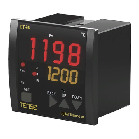
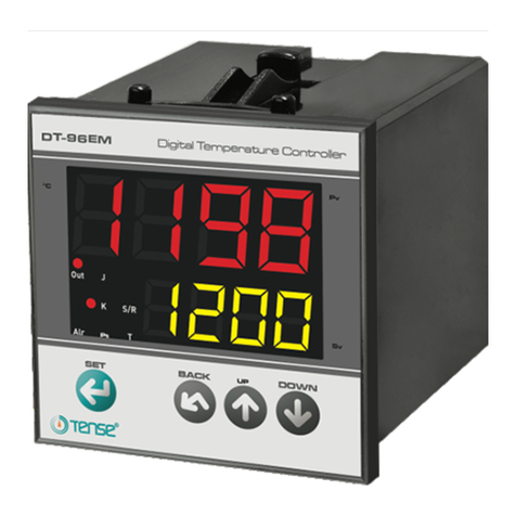
Tense DT-36EM User manual

DT-96EM / DT-72EM / DT-48EM / DT-36EM
AUTO-TUNE PID SICAKLIK KONTROL CİHAZI
Dikkat, Yüksek Gerilim, Çift / Takviyeli Çöpe CE İşareti
Tehlike Riski, Uyarı Elektrik Çarpması Tehlikesi Yalıtımlı Atmayın
TEKNİK ÖZELLİKLER
•Ebat : DT-96EM:96x96, DT-72EM:72x72, DT-48EM:48x48, DT-36EM:35x77mm
•Pano Kesiti : DT-96EM:91x91, DT-72EM:68x68, DT-48EM:46x46, DT-36EM :29x71mm
•Gösterge : 4 Hane 7 Segment PV, 4 hane 7 Segment SV
•Giriş: J, K, T, S, R tipi T/C, Pt100, seçmeli
•Ölçme Skalası : -100 .. 600
o
C, J tip T/C (Inpt=J), -100.0 .. 600.0
o
C, J tip T/C (Inpt=J.0)
-100 .. 1300
o
C, K tip T/C (Inpt=k), -100.0 .. 999.9
o
C, K tip T/C, (Inpt=k.0)
-100 .. 400
o
C, T tip T/C (Inpt=t), -100.0 .. 400.0
o
C, T tip T/C (Inpt=t.0)
0 .. 1750
o
C, S tip T/C (Inpt=S) 0 .. 1750
o
C, R tip T/C (Inpt=r)
-100 .. 600
o
C, Pt100, (Inpt=Pt) -100.0 .. 600.0
o
C, Pt100, (Inpt=Pt.0)
•Duyarlık : ± 1
o
C veya ± 0.1
o
C
•Doğruluk : ± % 1 (Tam Skalanın)
•Kontrol Formu : ON-OFF veya P, PI, PD, PID - seçmeli
•Kontrol Çıkışları : Röle, 250VAC, 2A, rezistif yük / SSR (12Vdc, 20mA) - seçmeli
•Heat SET Ayarı : Lo.L .. UP.L
o
C (H.Set)
•Heat Histeresiz : 0 .. 50 / 0.0 .. 50.0
o
C (H.hys); 0 ise PID kontrol seçilir
•Oransal Bant : 5 .. 150
o
C (Pb.C)
•İntegral Zamanı : 0:00 .. 30:00 dak:sn. (0:00 ise OFF)
•Türev Zamanı : 0:00 .. 10:00 dak:sn. (0:00 ise OFF)
•Kontrol Periyodu : 1 .. 200 sn (Ct)
•Ofset : -100..+100
o
C / -100.0 .. +100.0
o
C (oFFS)
•Isıtma/Soğutma : Sadece ısıtma fonksiyonu
•Ortam Sıc. Komp. : 0 .. 50
o
C (T/C)
•Hat Komp. : 10 Ohm maks. (3 telli Pt100)
•Sensör Koruması : Sensör veya sensor hattı koparsa, ölçme skalası dışına çıkılırsa veya giriş
ölçümü başarısız olursa OUT çıkışı P.Err ve Ct değerlerine göre aktif olur
(Perr 0 ise aktif olmaz, OFF).
•Besleme Voltajı : 100..240VAC, 50-60Hz - veya
(Opsiyonel; 24VDC/AC, maksimum
izolasyon gerilimi: 40VAC)
•Güç Tüketimi : < 8VA
•Bağıl Nem : < %70 (yoğunlaşmasız)
•İşletme irtifası : < 2000 m
•EMC : EN 61000-6-1, EN 61000-6-3 (Sadece hafif sanayi ortamı)
•Güvenlik : EN 61010-1; Kirlenme derecesi 2, ölçme sınıfı II
(Sadece hafif sanayi ortamı, çift/takviyeli yalıtımlı)
•Koruma Sınıfı : IP20; EN 60529'a göre
•Sıcaklık : Çalışma: 0 .. 50
o
C; Depolama :-10
o
C .. 60
o
C (buzlanma olmadan)
•Ağırlık : < 0.5 kg
•Klemens Sıkma Torku: en fazla 0.5 N.m
UYARI:
2 telli Pt100 kullanılıyorsa, kompanzasyon ucunu ölçüm ucuna
cihaz klemensi üzerinden köprüleyin: (DT-96EM:17-18, DT-72EM: 13-14,
DT-48EM: 10-11, DT-36EM: 9-10)

KURULUM, KULLANIM ve UYARILAR
●
Bu cihaz ve ambalajı çöp değildir. Bu cihazın ambalajını veya bu cihazı, kullanım süresi dolduğunda çöpe
atmayınız, uygun bir geri dönüşüm noktasına iletiniz.
●
Kullanım ve montaj öncesi cihazın kullanıcı kılavuzunu tamamen ve dikkatlice okuyunuz. Bu kılavuzdaki
uyarıları dikkate alınız.
●
DT-96EM, DT-72EM, DT-48EM, DT-36EM panel tipi sabit montaj için uygundur.
●
Cihazın montajı ve kullanımı yetkili ve eğitimli personel tarafından yapılmalıdır.
●
Montaj öncesi, cihazı göz kontrolünden geçirin. Hasarlı veya arızalı cihazın montajını yapmayınız.
●
Cihazın içini açmayınız, devrelerine müdahale etmeyiniz. Cihazın içinde kullanıcı tarafından değiştirilebilecek
bir parça yoktur. Arızalı cihazın onarımı için üretici firmaya başvurunuz.
●
Cihaz, yanabilir veya patlayabilir gazların ve/veya maddelerin bulunduğu ortamlarda veya aşındırıcı
atmosferik ortamlarda kullanılmaz.
●
Bu cihaz sadece hafif sanayi ortamında kullanım için tasarlanmıştır. Bu cihaz, ev kullanımına ve tıbbi amaçlı
kullanıma uygun değildir. Bu cihaz, insan sağlığı ve güvenliği ile ilgili uygulamalar için uygun değildir. Bu cihaz
otomotiv, askeri ve denizcilik uygulamaları için uygun değildir.
●
Cihazı, çocukların ve yetkisiz kişilerin kullanmasına izin verilmemelidir.
●
Çarpılmaya karşı, montaj sırasında bütün elektrik beslemelerini kesiniz.
●
Cihaza enerji vermeden önce besleme gerilimini kontrol ediniz, uygun olmayan gerilimi uygulamayınız. Cihaza
bağlanan nötr hattının uygunluğunu denetleyiniz. Hatalı nötr hatları cihaza kalıcı hasar verebilir.
●
Cihaz şebeke/besleme girişinde harici bir sigorta (1A, 250VAC) ve devre kesici anahtar kullanınız. Her bir röle
çıkışı için ayrı ayrı harici bir sigorta (2A, 250VAC) kullanınız.
●
Şebeke bağlantıları için uygun kablo kullanınız. Güvenlik kurallarına uygun montaj yapınız.
●
Cihazı, hava dolaşımının olduğu bir panoya, uygun ölçüde hazırlanmışpano kesitine, iki adet kıstırma parçası
ile sıkıca ve sağlam bir şekilde, bağlantı klemens noktalarına kullanıcının erişemeyeceği şekilde monte ediniz.
●
Cihazı,“Teknik Özellikler” bölümünde belirtilen çevresel şartlar dışındaki şartlarda kullanmayınız.
●
Cihazı, iletken kirlilik oluşabilecek ortamlarda kullanmayınız.
●
Cihazı, rutubet, titreşim, kirlilik ve yüksek/düşük sıcaklık gibi olumsuz çevresel şartlara karşı korunaklı şekilde
monte ediniz.
●
T/C kullanıldığı durumlarda, doğru kompanzasyon kablosu kullanınız, ek yapmaktan kaçınınız, cihaz klemens
bağlantısına kadar T/C kablosu kullanınız.
●
Cihazı, sinyal ve haberleşme kablolarını kontaktör, elektriksel gürültü yayan cihazlar ve enerji taşıyan
hatlardan uzak tutunuz. Ekranlı ve burgulu sinyal ve haberleşme kabloları kullanıp ekranı cihaz tarafından
topraklayınız. Sinyal ve haberleşme kablolarının uzunluğunu 3m'den kısa olacak şekilde monte ediniz.
●
Uygulamalarınızda, acil durumlar (Acil STOP, aşırı basınç tahliyesi ve benzeri) için DT-96EM, DT-72EM, DT-
48EM, DT-36EM'den başka ve bağımsız mekanik ve/veya elektro mekanik yardımcı ekipman kullanınız.
Başka ekipmanlarla desteklenmişuygun ve garantili acil durum tasarımı yapınız.
●
Cihaz klemenslerine bağlanacak kablo uçlarına izoleli kablo pabuçları takınız.
●
Klemens sıkma torku; en fazla 0.5 N.m dir.
●
Yazılım ve dokümantasyon güncellemeleri için sık sık “www.tense.com.tr”yi ziyaret edin. Güncellemeler
kullanıcılar haberdar edilmeksizin yapılabilir.
GENEL ÖZELLİKLER
●
Bu cihaz, sadece hafif sanayi ortamlarında temel sıcaklık kontrol uygulamaları için tasarlanmıştır.
●
PID sıcaklık kontrol cihazı
●
Auto-tune özelliği ile PID parametrelerini otomatik hesaplama
●
Sensör tipi: T/C (J,K,T,S,R), Pt100, seçmeli - multi input
●
P, PI, PD, PID veya ON-OFF kontrol formu - seçmeli
●
Rampa özelliği - PID modunda, “Anti-windup” özelliği
●
Set değeri için üst ve alt limit seçme imkanı
●
Set ve Proses değerlerinin aynı anda izlenebilme imkanı
●
T/C için ortam sıcaklık kompanzasyonu, Pt100 için hat kompanzasyonu
●
Hafızada kayıtlı oC/mV ve oC/Ohm dönüşüm tabloları ile eğri düzeltme
●
Ölçüm değerine “Offset” ekleme imkanı
●
Şifre korumalı
●
Yüksek hassasiyet, doğruluk
●
Program ve kontrol parametrelerini sürekli hafızada tutabilme
●
Soketli klemens ile kolay bağlantı imkanı
TENSE Elektronik www.tense.com.tr
2

PARAMETRELERİN AYARLANMASI
(1) Sensör tipi değiştirilirse; seçilen sensör tipine göre Hata Mesajları:
Up.L, Lo.L, H.Set, H.hys, oFFs Fail: Sensör kopuk veya hatalı seçilmiş
değerleri otomatik olarak düzeltilir (değerleri değişebilir). E.FLS: Donanım arızalı, teknik destek alın
(2) Sensör tipi J.0, K.0, t.0 veya Pt.0 seçilirse E.CAL: Donanım arızalı, teknik destek alın
E.EPr: Bellek hatası, teknik destek alın
TENSE Elektronik www.tense.com.tr
3
SET
H.hys
0..50 /
0.0 .. 50.0
o
C (2)
SET
Heat Histeresiz değeri.
0 ise PID kontrol formu
seçilir.
Pb.C
5 .. 150
o
C
SET
Ct
1 .. 200 sn.
SET
oFFS
-100 .. +100 /
-100.0 .. +100.0 (2)
o
C
SET
td
0:00 ..10:00
dak:sn
SET
+
Fabrika Ayarları:
H.SEt: 100
o
C
Inpt : J
H.hys: 0
o
C
Pb.C: 30
o
C
Ct: 4 sn
ti: 5:00 dak:sn
td: 1:00 dak:sn
UP.L: 400
o
C
Lo.L: 0
o
C
oFFS: 0
o
C
Out : r-S
P.Err: 0
C-t: 0.0
o
C/dak
L.dSP: yes
o.Sht: oFF
SECU: AH
CodE 162 gir
SET
UP.L
Lo.L ..
Üst Skala (
o
C)
SET
Lo.L ve H.SET için Üst limit.
Üst Skala değeri seçilen
sensör tipine göre değişir.
Out
SET
ti
0:00 .. 30:00
dak:sn
SET
Inpt
Sensör Tipi (1)
SET
J, J.0: J tipi T/C
K, K.0: K tipi T/C
t, t.0: T tipi T/C
S: S tipi T/C
r: R tipi T/C
Pt, Pt.0: Pt100
Lo.L
Alt Skala ..
UP.L (
o
C)
SET
Up.L ve H.SET
için Alt limit. Alt Skala değeri
seçilen sensör tipine göre değişir.
P.Err
% 0..100
SET
Ölçüm yapılamadığı durumda (“Fail” mesajı okunduğunda) OUT
çıkışı Ct periyodunun % P.Err kadarı süre ile ON (aktif) olur. 0
seçilir ise OUT OFF olur. 100 seçilirse OUT sürekli ON olur.
H.Hys
0’dan
farklı
Back
İntegral Zamanı:
dak:sn cinsinden
ayarlanır. 0:00 seçilirse,
P, PD kontrol seçilir.
Türev Zamanı:
Dak:sn cinsinden
ayarlanır. 0:00 seçilirse,
P, PI kontrol seçilir.
Oransal Band
Genişliği (
o
C)
Kontrol Periyodu
(saniye)
Offset Değeri. Bu değer
Ölçme değerine ilave edilir.
Kullanıcı kalibrasyonu için
kullanılabilinir. Normalde 0 dır.
Parametre programlama
moduna geçmek için
Şifre olarak 162 girilir
Üst Gösterge
rLY, SSr , r-S
ÇıkışTipi:
rLY: Sadece Röle çıkışı aktif
SSr: Sadece SSR çıkışı aktif
r-S: Röle ve SSR çıkışları beraber aktif
CodE “auto-tune”
başlatmak
için “262”
girin
SET
Üst Gösterge
“tunE”
yanıp söner
•“Auto-tune” başlatılmadan önce H.SEt ayarlanmalıdır.
•“Auto-tune” sırasında proses değeri H.SEt değerini
geçebilir.
•“Auto-tune” başarılı ise, kontrol formu otomatik
olarak PID olur.
•“Auto-tuning”, herhangi bir tuşa basılarak
iptal edilebilir. Bu durumda, “auto-tuning”
başlatılmadan önceki değerler geçerlidir.
•“Auto-tuning” her zaman en iyi PID parametrelerini
hesaplayamayabilir.
Parametre
programlama
sırasında
“Back”
tuşuna
basılırsa,
başa dönülür.
2 sn. bas
C-t
0.0 .. 300.0
o
C / dak
SET
Cihaz enerjilendiğinde C-t değeri 0'dan farklı ise rampa
başlar. Set değeri, H.Set değerine gelene kadar dakikada
“C-t” değeri kadar arttırılır.
CodE Fabrika
ayarlarına
dönmek için
“555” girin
SET
Üst Gösterge
“YES” / “nO”
•Fabrika ayarlarına dönmek için;
Code -> 555 girin,
”yes” seçip “SET”e basın.
L.dSP
yes .. no
SET
yes: Alt gösterge açık
no: Alt gösterge kapalı
Prog. sonu
o.Sht
OFF, 10.0,
5.0, 3.0,
1.0, 0.2
SET
SECU H, -
SET
H : HEAT SET ayarlanabilir,
- : HEAT SET ayarlanamaz.
Pik (Over Shoot) Engelleme: Off dışındaki seçenekler pik atma miktarını
azaltabilir ancak kararlılığı bir miktar bozabilir. Bu nedence önce;
OFF ile deneyin, sonra 10.0->5.0->3.0->1.0->0.2 sırası ile deneyin.
1.0 ve 0.2 seçenekleri kararlılığı en çok bozabilecek seçeneklerdir.
OFF: Kapalı, 10.0: 10 dereceye , 5.0: 5 dereceye, 3.0: 3 dereceye,
1.0: 1 dereceye, 0.2: 0.2 dereceye (SET değeri üzeri) izin ver.
H.Hys
0’dan
farklı

HEAT SET DEĞERİNİN AYARLANMASI
ÇIKIŞ(ON-OFF Çalışma Modu)
“H.hys”
değeri “0” dan farklı ise ON-OFF kontrol formu aktif olur.
PID PARAMETRELERİ
- “H.hys” değeri “0” ise PID kontrol formu aktif olur.
- PbC: Oransal Bant Değeri, zaman oransal çalışmanın H.SET değerine kaç derece kala başlayacağını belirtir. Oransal Bant
(H.SET) derecede sona erer.
- Ct: Kontrol periyodu; iyi bir kontrol için 1 - 10 saniye seçilmelidir.
- Ti: İntegral zamanı; proses değeri ile SET değeri arasında oluşan fark, PID algoritması tarafından kompanse edilir. Ti değeri
azaldıkça cevap süresi kısalır. Proses değerinin salınıma girmemesi için aşırı düşük Ti değerlerden kaçınılmalıdır. Ti değeri 0
olursa, algoritmanın İntegral kısmı göz ardı edilir; algoritma P veya PD olarak çalışır.
- Td: Türev zamanı; proses değeri ile SET değeri arasındaki ani değişimler PID algoritması tarafından kompanse edilir. Td
değeri arttıkça ani değişimlere duyarlılık artar. Bu nedenle aşırı yüksek Td değerlerinden kaçınılmalıdır. Td değeri 0 olursa,
algoritmanın Türev kısmı göz ardı edilir; algoritma P veya PI olarak çalışır.
TEMİZLİK
Cihazı solvent (alkol, tiner, benzin, asit, vb.), solvent içeren veya aşındırıcı temizlik maddeleriyle temizlemeyiniz.
Sadece kuru, temiz bir bezle temizlenebilir. Temizlik sırasında cihazın bütün elektrik beslemeleri kesik olmalıdır.
TENSE Elektronik www.tense.com.tr
4
H.SET(H.SET-H.Hys) PV
OUT ISITMA
2 sn. bas
SET
H.SEt
Lo.L .. UP.L
o
C
Prog. sonu
Üst Gösterge
SET
Heat SET,
(Proses SET)
değeri, Lo.L’den UP.L değerine
kadar ayarlanabilir.

DT-96EM / DT-72EM / DT-48EM / DT-36EM
AUTO-TUNE PID TEMPERATURE CONTROLLER
Attention, Risk of, High Voltage, Double / Reinforced NOT CE Mark
Danger, Warning Risk of Electric Shock Insulation Litter
TECHNICAL SPECIFICATION
•Dimensions : DT-96EM:96x96, DT-72EM:72x72, DT-48EM:48x48, DT-36EM:35x77mm
•Panel Cut-out : DT-96EM:91x91, DT-72EM:68x68, DT-48EM:46x46, DT-36EM :29x71mm
•Display : 4 Digits 7 Segment (PV), 4 digits 7 Segment (SV)
•Sensor Type : J,K,T,S,R type T/C, Pt100 selectable
•Measuring Scale : -100..600
o
C, J type T/C (Inpt=J), -100.0 .. 600.0
o
C, J type T/C (Inpt=J.0)
-100..1300
o
C, K type T/C (Inpt=k), -100.0..999.9
o
C, K type T/C, (Inpt=k.0)
-100..400
o
C, T type T/C (Inpt=t), -100.0 .. 400.0
o
C, T type T/C (Inpt=t.0)
0..1750
o
C, S type T/C (Inpt=S) 0 .. 1750
o
C, R type T/C (Inpt=r)
-100..600
o
C, Pt100, (Inpt=Pt) -100.0 .. 600.0
o
C, Pt100, (Inpt=Pt.0)
•Resolution : ± 1
o
C or ± 0.1
o
C
•Accuracy : ± 1 % (Over full scale)
•Control Form : ON-OFF or P, PI, PD, PID - selectable
•Control Output : Relay, 250VAC, 2A, resistive load / SSR (12Vdc, 20mA) - selectable
•Heat SET : Lower Limit .. Upper Limit
o
C (H.Set)
•Heat Hysteresis : 0 .. 50 / 0.0 .. 50.0
o
C (H.hys); PID is active if set to 0
•Proportional Band : 5 .. 150
o
C (Pb.C)
•Integral Time : 0:00 .. 30:00 min:sec. (OFF if set to 0:00)
•Derivative Time : 0:00 .. 10:00 min:sec. (OFF if set to 0:00)
•Control Period : 1 .. 200 sec. (Ct)
•Offset : -100..+100
o
C / -100.0 .. +100.0
o
C (oFFS)
•Heating/Cooling : Only heating function
•Cold. Junc. Comp. : 0 .. 50
o
C (T/C)
•Line Comp. : 10 Ohm max. (3 wire Pt100)
•Sensor Failure : OUT output is active according to P.Err and Ct parameters in case of
sensor failure, measurement out of range or hardware fails to measure
input signal (OUT output is OFF if Perr is 0).
•Supply Voltage : 100..240VAC, 50-60Hz - or
(Optional; 24VDC/AC, maximum isolation voltage: 40VAC)
•Power Consumption : < 8VA
•Humidity : < 70% (non-condensing)
•Altitude : < 2000 m
•EMC : EN 61000-6-1, EN 61000-6-3 (Only light industrial environment)
•Safety : EN 61010-1; Pollution degree 2, measurement category II
(Only light industrial environment, double/reinforced isolated)
•Protection Class : IP20; according to EN 60529
•Temperature Spec. : Operating: 0 .. 50
o
C, Storage -10
o
C .. 60
o
C (no icing)
•Weight : < 0.5 kg
•Torque for screwing : Max. 0.5 N.m
WARNING:
if 2 wire Pt100 is used, connect compensation
lead to measuring lead:(DT-96EM:17-18, DT-72EM: 13-14,
DT-48EM: 10-11, DT-36EM: 9-10)

INSTALLATION, USE and WARNINGS
●
This device and its packing is NOT litter and may NOT be disposed of with domestic waste. Please return
this device and its packing to an appropriate recycling point at the end of its service life.
●
Please read this user manual carefully and completely before installation and use. Please take into
consideration all warnings mentioned in this manual.
●
DT-96EM, DT-72EM, DT-48EM, DT-36EM are suitable only for permanent panel type mounting.
●
Installation and use of this device must be done by qualified, authorized and trained technical personnel only.
●
Inspect device carefully before installation. Do not install and use broken and defective devices.
●
Do not disassemble device. Do not make any repair on any part of the device. There is no accessible part
inside the device. Please contact to manufacturer for broken and defective devices.
●
Do not use device in environments subject to flammable, explosive and corrosive gases and/or substances.
●
This device is designed for applications only in light industrial environments. This device is not suitable for
medical and residential use. This device is not suitable for use related with human health and safety. This
device is not suitable for automotive, military and marine use.
●
Do not allow children and unauthorized people to use this device.
●
Before installation and any technical work, disconnect the power supply and mains connections.
●
Check the power supply voltage level before power on, and make sure voltage level is in specified limits.
Check quality of neutral line. Improper neutral line may give permanent damage to the device.
●
Connect an external power switch and an external fuse (1A, 250VAC) to the power supply line that are easily
accessible for rapid intervention. Connect an external fuse (2A, 250VAC) for each relay output separately.
●
Use appropriate cables for power supply and mains connections. Apply safety regulations during installation.
●
Install the device in a well ventilated place. Install the device permanently into a proper panel cut-out. Fix the
device with two fasteners supplied with the device. Only front panel must be accessible after installation is
completed.
●
Do not operate the device other then the environmental conditions given in Technical Specification.
●
Do not operate the device in environments that may cause conductive pollution.
●
Take precautions against negative environmental conditions like humidity, vibration, pollution and high/low
temperature during installation.
●
Use correct compensation cables for T/C sensors. Connect T/C cable directly to the device connectors.
●
Keep device, signal cables and communication cables away from circuit breakers, power cables and
devices/cables emitting electrical noise. Use shielded and twisted signal and communication cables and
connect shield to earth ground on device side. Keep length of signal and communication cables less than 3m.
●
In your applications, always use separate and independent mechanical and/or electromechanical
devices/apparatus to support DT-96EM, DT-72EM, DT-48EM, DT-36EM to handle emergency cases.
●
Use insulated cable end-sleeves at the end of cables screwed to the device connector terminals.
●
Maximum torque for screwing; 0.5 N.m.
●
Please check www.tense.com.tr for latest device and documentation updates regularly. All updates and all
information are subject to change without notice.
GENERAL SPECIFICATION
●
This device is designed for basic temperature control applications only in light industrial environments.
●
PID temperature controller
●
Auto-tuning for PID parameters
●
Sensor type: T/C (J,K,T,S,R), Pt100, selectable, multi-input
●
Selectable control type: P, PI, PD, PID or ON-OFF
●
Ramp mode during power on
●
“Anti-windup” in PID and PI mode
●
Upper and Lower limit for SET setting
●
Displays SET and PROCESS values
●
Cold-junction compensation for T/C
●
Line compensation for Pt100
●
Excellent linearity with oC/mV and oC/Ohm look-up tables
●
Input “Offset” feature
●
Password protection
●
High accuracy
●
EEPROM memory to store settings
●
Easy connection with plug-in connectors
TENSE Elektronik www.tense.com.tr
2

PROGRAMMING PARAMETERS
(1) When sensor type is changed, Up.L, Lo.L, H.Set, H.hys, oFFs Error Messages:
may be set to a new value automatically, according to the selected sensor. Fail: Sensor failure or sensor selection wrong
(2) If sensor type is selected as Pt.0, J.0, K.0 or t.0. E.FLS: Hardware failure
E.CAL: Hardware failure
E.EPr: Memory failure
TENSE Elektronik www.tense.com.tr
3
SET
H.hys
0 .. 50 /
0.0 .. 50.0 (2)
o
C
SET
Heat Hysteresis (
o
C):
PID is active if set to 0
Pb.C
5 .. 150
o
C
SET
Ct
1 .. 200 sec
SET
oFFS
SET
td
SET
+
CodE Enter 162
SET
UP.L
Lo.L ..
Upper Scale (
o
C)
SET
Upper limit value for Lo.L
and H.SET. Upper Scale
value differs according to
the selected sensor type.
Out
SET
ti
0:00 .. 30:00
min:sec
SET
Inpt
Sensor Type (1)
SET
J, J.0: J type T/C
K, K.0: K type T/C
t, t.0: T type T/C
S: S type T/C
r: R type T/C
Pt, Pt.0: Pt100
Lo.L
Lower Scale ..
UP.L (
o
C)
SET
Lower limit value for UP.L,
H.SET. Lower Scale value
differs according to the selected
sensor type.
P.Err
% 0 .. 100
SET
Determines the duty cycle of OUT output
when “Fail” message is displayed. If 0, OUT is always
OFF. If 100, OUT is always ON, when device “fails”.
Period is Ct.
H.Hys
not 0
Back
Press “Back”
to return to the
top of
parameters
programming
block
Integral Time:
In min:sec If set to 0:00,
P, PD is active (integral OFF).
Derivative Time:
In min:sec. If set to 0:00,
P, PI is active (derivative OFF).
Proportional Band in (
o
C)
Control period (sec)
Offset Value; Offset is directly added
to the measured value. This feature shall
be used for user calibration. Normally set to 0.
Enter 162 to pass
to parameter prog. mode
Press for 2 sec.
Upper Display
rLY, SSr , r-S
Control OUT Type:
rLY: Only Relay is active
SSr: Only SSR is active
r-S: Both Relay and SSR are active at the same time
CodE
Enter “262”
to start
auto-tune
SET
Upper Display
“tunE”
flashes
•Before starting Auto-tune, adjust H.SET.
•Process value may exceed H.Set during auto-tuning.
•After auto-tuning, control form automatically switches
to PID mode.
•Auto-tuning is stopped (interrupted) any time by
pressing any key. In this case, the parameters before
auto-tuning is valid.
•Auto-tuning may not always determine the best values
for your process.
Factory SET Values:
H.SEt: 100
o
C
Inpt : J
H.hys: 0
o
C
Pb.C: 30
o
C
Ct: 4 sec
ti: 5:00 min:sec
td: 1:00 min:sec
UP.L: 400
o
C
Lo.L: 0
o
C
oFFS: 0
o
C
Out : r-S
P.Err: 0
C-t: 0.0
o
C / min
L.dSP: yes
o.Sht: oFF
SECU: AH
0:00 .. 10:00
min:sec
-100 .. 100 /
-100.0 .. 100.0 (2)
O
C
C-t
0.0 .. 300.0
o
C / min
SET
If C-t is not 0, ramping starts after power on.
SET value is incremented C-t degrees per minute
until SET reaches H.SEt.
CodE
Enter “555”
for factory
reset
SET
“YES” / “nO”
•To return to factory settings:
Code > 555 > select “yes” >
Press “SET”
Upper Display
yes: Lower display ON
no: Lower display OFF
SET
L.dSP
yes .. no
End Prog.
o.Sht
OFF, 10.0,
5.0, 3.0,
1.0, 0.2
SET
SECU
H, -
SET
H : “HEAT SET” may be adjusted,
- : “HEAT SET” may NOT be adjusted
Over shoot reduction: All options other than “OFF” may help to reduce over
shoot more but also may increase instability around SET point. For this reason;
First try “OFF” option then 10.0->5.0->3.0->1.0->0.2 options if needed.
Options 1.0 and 0.2 are most sensitive and may result more instability around
SET point among other options. With this parameter, over shoot is not allowed
more than; OFF: not limited, 10.0: 10 , 5.0: 5 , 3.0: 3 , 1.0: 1 , 0.2: 0.2 degrees
(over SET point).
H.Hys
not 0

PROGRAMMING HEAT SET
(ON-OFF CONTROL)
ON-OFF is active when
“H.hys”
is other then 0
PID PARAMETERS
- P, PI, PD, PID is active when “H.hys” is set to 0.
- PbC: Proportional band in oC.
- Ct: Control period for PID control. Prefer 4-10 sec.
- Ti: Integral time; Set in minutes. Determines how fast controller reacts to compensate the offset between SET point and the
process value. If set to 0, integral part is OFF. If set too low, process value may oscillate.
-Td: Derivative time; Set in minutes. If set to 0, derivative part is OFF. Determines how sensitive the controller is to changes of
the offset between SET point and the process value. If set too high, process value may oscillate or overshoot.
CLAEANING
Do not use any solvents (alcohol, thinners, benzine, acid, etc.) or corrosive substances to clean the device. Use only a dry
and clean non-abrasive cloth. Before cleaning, disconnect the power supply and mains connections.
TENSE Elektronik www.tense.com.tr
4
H.SET(H.SET-H.Hys)
PV
OUT Heating
Press 2 sec. SET
H.SEt
Lo.L .. UP.L
o
C
Prog. end
Upper Display
SET
Heat SET;
(Process SET)
value is
set Lo.L .. UP.L
This manual suits for next models
3
Table of contents
Languages:
Other Tense Controllers manuals
Popular Controllers manuals by other brands
Cumberland
Cumberland Evolution Back-Up owner's manual
Coremorrow
Coremorrow XE-650 Series user manual
Twinkly Pro
Twinkly Pro TWPRO1000ETHP user guide
Allen-Bradley
Allen-Bradley PowerFlex400 user manual
Magnetek
Magnetek Impulse G+ series 4 instruction manual

STORK TRONIC
STORK TRONIC ST710-PWHVR.126 Wiring diagram
Automation Devices
Automation Devices 6005 Series instructions

Thermo Scientific
Thermo Scientific Unity Lab Services UP150 Operation
alre
alre KTRRB-042.211 quick start guide

Emerson
Emerson Fisher T205 installation guide

BZ PRODUCTS
BZ PRODUCTS M20+ installation manual

Siemens
Siemens MEC 1100 installation instructions
