Baur PGK 70 HB User manual
0-1
06/00
Ident.No.822-085
Operating manual
High Voltage Testing Sets
PGK 70 HB
PGK 70 - 2,5 HB
PGK 110 HB
PGK 150 HB
PGK 260 HB
BAUR Prüf- und Messtechnik GmbH
Raiffeisenstrasse 8, A-6832 Sulz / Austria Tel +43 / 55 22 / 49 41-0
Fax +43 / 55 22 / 49 4 13
e-mail: headoffice@baur.at
internet: http://www.baur.at

0-2
0-3
Forfast finding of importantinformationthecorrespondingtext
passages are marked with symbols (symbols not stated here are
self-explaining).
Moreandspecial information concerningtherespective subject are
availablefromBAUR.
Importantunitinformation!
In any case, read carefully!
Importantinformationtext.
Observe
info signs!
☞
Guide to this Operating Instruction
Copyright
© BAUR Prüf- und Messtechnik GmbH,
A-6832 Sulz /Austria
Allrightsreserved.
No part of this publication may be reproduced, transmitted, stored in
adataprocessin gsystem ortranslated into another language
without the written permission of BAUR / Sulz,Austria.
Inthe interest ofour customers wereserve the rightsfor
modificationsdue to technicalprogress. Illustrations, descriptions
anddeliverycontentare therefore not binding.
© Copyright by BAUR
Thismanual containsall information necessaryfor the correct
handling and use of the high voltage testing set PGK 70 HB,
PGK 70 - 2,5 HB, PGK 110 HB, PGK 150 HB und PGK 260 HB.
Beforeusingthe surge voltagegenerator, please read carfullythis
OperatingInstruction.
Preface
If you have any question, please contact directly
BAURPrüf- und MesstechnikGmbH,Raiffeisenstrasse8
A-6832 Sulz /Austria
orreferto your nearest BAURrepresentative.
Please read now and
avoid damage and injury later!
- The PGK 70 HB, PGK 70 - 2,5 HB, PGK 110 HB, PGK 150 HB
und PGK 260 HB is built in accordance with today's state of
engineeringandissafe to operate. Individualcomponentsand
thefinished unit areinspected continually byour qualified staff
withinthe framework ofour QualityAssuranceProvisions. Each
unit is subjected to thorough testing prior to shipment.
Guide to this Operating Instruction, Copyright, Preface
Subject to modification!
Safety Precautions
Tel +43 / 55 22 / 49 41-0
Fax +43 / 55 22 / 49 41 3

0-4
- Itisimperative to everypersonwho is involvedwiththe
installation,start-up,operationandmaintenanceto have read and
understoodthecomplete Operating Instruction.
- It is the responsibility of the customer to ensur that only
authorizedpersons may beallowed to usethe high voltage
testing sets.
Theuser
- isqualivied and properlyinstructed and hasthe necessary
experience.
- knowstherelevant standards,accidentprevention rules and
operatingconditions.
- is able to carry out the necessary operations and is aware of
thepossibledangersinvolved.
- must immediately inform his superior about any conditions of
the unit that could affect safety.
Thehigh voltage testing setsaretobe applied exclusivelyfor
voltageprooftestingof electrical equipment.
The local safety and accident prevention requirements are
always applicable to the operation of the PGK 70 HB, PGK
70 - 2,5 HB, PGK 110 HB, PGK 150 HB and PGK 260 HB unit.
At the customer's written request we undertake to repair or replace
at our discretion and as quickly as possible all parts that become
faulty or useless as the demonstrable results of poor material, faulty
designordefectiveexecution.
We bear the costs for repairs and replaced parts, exclusive
transportationofthe goods, packingandinsurance.
The12 month warranty time startswithdelivery.
We shall bear the costs of any faulty parts requiring replacement,
but not the costs of transport to us an back to the customer, not the
costs of packing and insurance! We shall not be liable for any
damageresultingfromnormal wear and tear, improperhandling,non-
observanceofOperating Instruction and safetyrequirements.We
shall also refuse to accept any liability if the customer carries out
repairs or changes to the unit himself or has others carry out them!
Thewarranty does notcover damage intransit, batteries, fuses and
anyreadjustmentsin accordance withtheOperating Instruction!
We draw attention in addition to the "General Terms of Sales and
Delivery" of.
Warranty
Safety Precautions, Warranty
Safety Precautions, Continued
Only authorized personnel!
Use the PGK 70 HB, PGK 70 - 2,5 HB,
PGK 110 HB, PGK 150 HB and
PGK 260 HB unit as directed!
12 month warranty time
BAURPrüf- und MesstechnikGmbH,Raiffeisenstrasse8
A-6832 Sulz /Austria

0-5
Contents
1. Product Information...................................................................... 1-1
Overview ...................................................................................... 1-1
Designandfunction ..................................................................... 1-2
Displayandoperating elements................................................... 1-4
Technicaldata ............................................................................. 1-5
PGKLoadcurves ........................................................................ 1-6
2. Packing and Shipping .................................................................. 2-1
Damageduringtransport ............................................................. 2-1
3. Placing into operation .................................................................. 3-1
Overview ...................................................................................... 3-1
Connectto earth.......................................................................... 3-2
Switch on .................................................................................... 3-2
Switchoff..................................................................................... 3-4
EMERGENCY-OFF ..................................................................... 3-4
Changeoperatingmode............................................................... 3-5
4. Servicing / Maintenance............................................................... 4-1
Overview ...................................................................................... 4-1
General ....................................................................................... 4-2
Fuse............................................................................................ 4-2
Contents

0-6
Contents, Continued
Contents
5. Options, Accessories and Ordering Information ..................... 5-1
Overview ...................................................................................... 5-1
Options ....................................................................................... 5-2
Accessories ................................................................................ 5-3
Orderinginformation .................................................................... 5-5

1-1
1. Product Information
Subject Page
Design and function 1-2
Display and operating elements 1-4
Technical data 1-5
PGK Load curves 1-6
1. Product-Information
Overview
This section contains all necessary information about the High
Voltage Testing Sets PGK HB.
This section contains the following subjects:
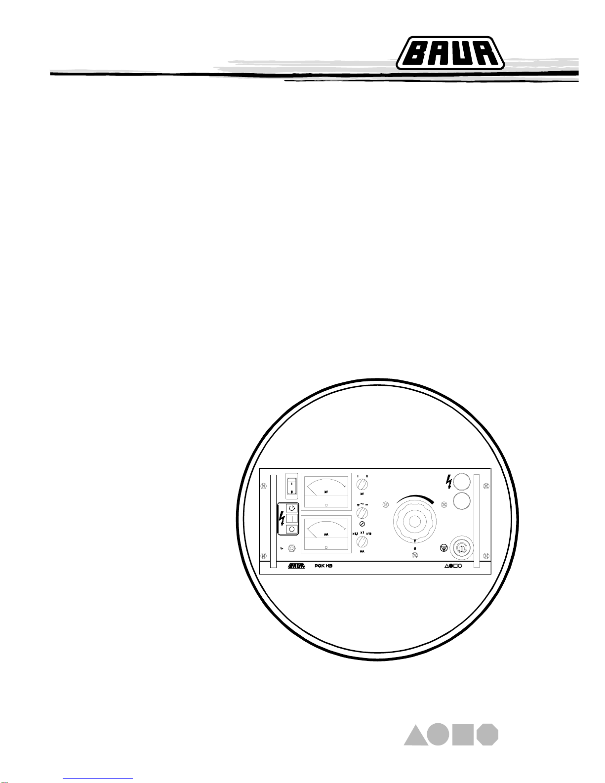
General view
PGK 70 HB

1-2
1. Product Information
Design and Function:
With the PGK 70 - 2,5 HB, PGK 110 HB, PGK 150 HB and the
PGK 260 the corona protection hood is used as oil expansion tank
(conservator) and may not be removed or damaged. With the
PGK 70 HB an air cushion in the housing (tube) works as a
compressible volume for absorbing the oil expansion. That’s why
the H.V. unit may only be stored, shipped and operated vertically.
Generation of high voltage is carried out by a H.V. transformer
supplied by an variable transformer. During D.C. operation a half-
wave rectifier is connected after the H.V. transformer. By turning the
half-wave rectifier the polarity of the output voltage can be changed.
The capacity of the test object acts as smoothing capacitor. During
A.C. operation, a damping resistor is connected to the H.V. circuit
instead of the half-wave rectifier (with PGK 260 HB: option - not
included)
The H.V. units of the PGK HB instruments are equipped with a
potential grading ring which can also be used as carrying ring. The
instruments may be not operated without this potential grading ring.
The PGK HB instruments are designed as two-part High Voltage
Testing Sets.
•Operating unit with all indicating/operating elements, with power
supply and safety devices.
•High Voltage unit as oil-filled housing with High Voltage trans-
former with the choice of a rectifier bar for half-wave rectification
or a resistance bar as a damping resistor.
Design
Depending on the load by the test object and the voltage set, the
PGK HB instruments are operating in one of the two operating
ranges Continuous Operation and Short-time Operation.
Continuous operation:
Within this operating range, from no-load to nominal rating up to
cut off load the instrument can be loaded continuously.
Short-time operation:
Within this operating range from cut off load to short circuit the
instrument switches current-limiting lamps into the primary circuit of
the H.V. transformer in order to reduce the thermal load of the
instrument.Additionally, as a protection against overload the
overcurrent protection switch (5) with its thermal and magnetic
tripping characteristic is tripped after a specific period terminating
operation. The time until tripping depends on load and takes from
seconds (during short-circuit) to hours (at maximum load).
☞
Operating ranges
High Voltage generation
☞

1-3
1. Product Information
The mA-meter is connected into the H.V. circuit on earth side.
D.C. operation:
The mA-meter shows the arithmethic mean value of the output
current.
A.C. operation: (option with PGK 260 HB)
The rectification value of theA.C. is measured by the instrument.
However, the display shows the appropriate rms value.That’s why
there can be deviations of the displayed value from the true rms
value if the measured current is not sinusoidle. During no-load the
mA-meter shows the current which flows via the self-capacitance of
the H.V. transformer. Must be considered during measurements on
test objects.
The kV-meter is connected to a tapping of the H.V. winding and is
current-compensated. The compensation is balancing the voltage
drop at the internal resistance of the test instrument.
D.C. operation:
The kV-meter shows the peak value of the output voltage. If the
self-capacitance of the test object is very low it is possible that the
insulation current of the test object results in a high ripple. In this
case, note that the displayed value and the arithmetic mean value
of the test voltage can be clearly different.
Display during A.C. operation:
(option with PGK 260 HB)
As with the mA-meter the kV-meter also measures the rectification
value and displays the rms value.
kV - meter
mA - meter
1-4
1. Product Information
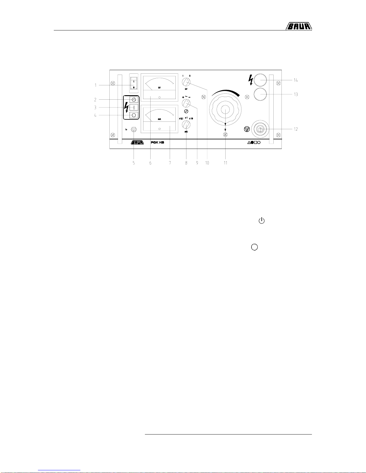
1Mains switch as overcurrent safety switch with thermal
tripping
2Pushbutton „Ready to switch on“ ( )
3Pushbutton „High Voltage On“ ( I) with pilot lamp
(clearing of H.V.)
4Pushbutton „High Voltage Off“ ( )
5Overcurrent safety switch with thermal and magnetic
tripping
6Voltmeter for display of output voltage in kV
7Amperemeter for display of output current in mA
8Measuring range switch for amperemeter
9Selector switch for operating mode (+ / ~ / -)
10 Measuring range switch for voltmeter
11 Variable transformer for setting the output voltage
12 Lockabel Emergency off momentary contact switch
13 Indicator lamp, green
14 Indicator lamp, red
Display and operating elements
1-5
1. Product Information
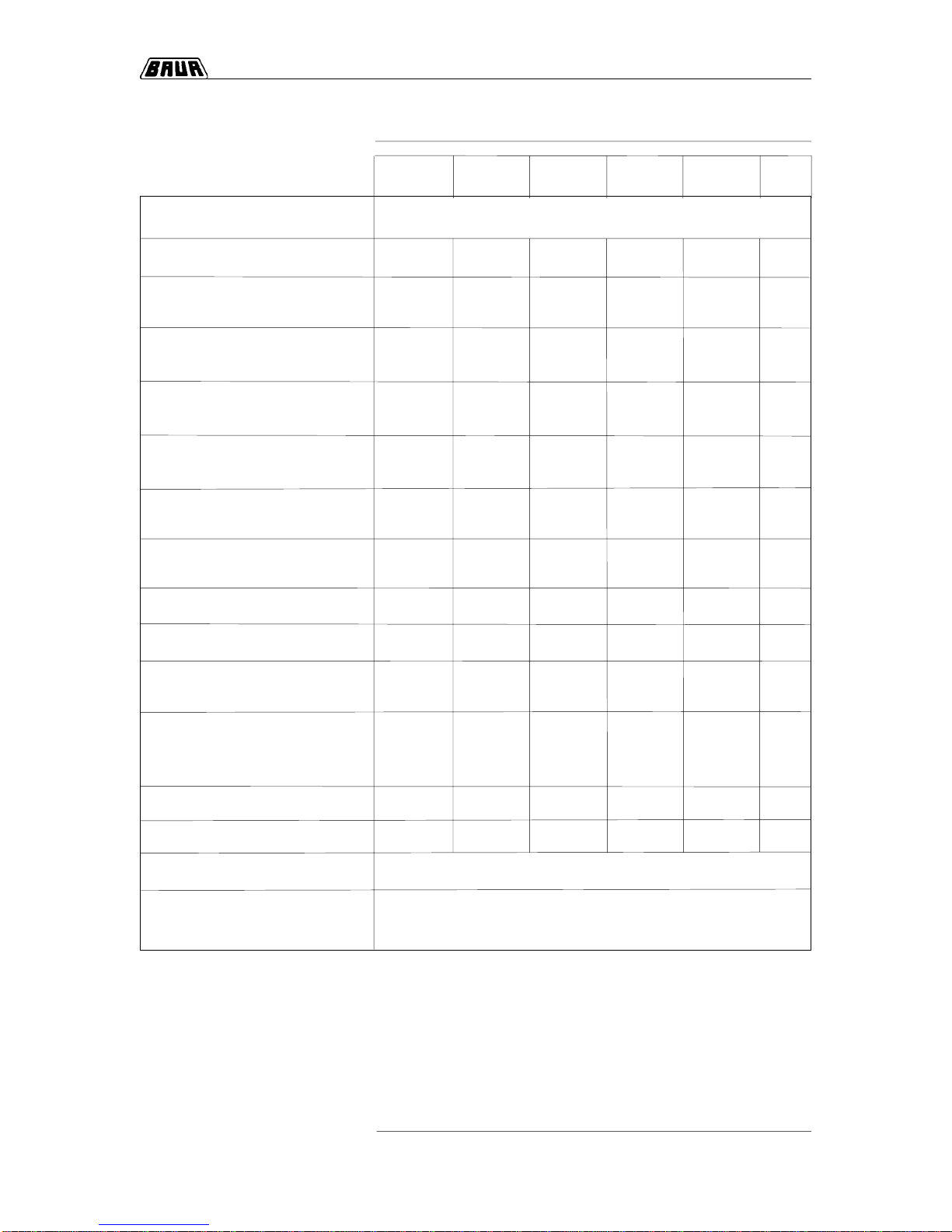
PGK PGK 70 PGK PGK PGK unit
70 HB - 2,5 HB 110 HB 150 HB 260 HB
Mains voltage see type plate V ~
Mains frequency 45 to 60 45 to 60 45 to 60 45 to 60 45 to 60 Hz
Power consumption at
nominal working point 640 3200 1380 1380 2600 VA
Max. power consumption
(in short-circuit operation) 1200 6500 2650 2650 5000 VA
Power output at nominal
working point AC/DC 330/190 2750/1260 1260/495 990/530 1665/1000 VA/W
Max. output voltage
ACeff/DC in no-load 56/78 56/78 94/126 110/160 185/260 kV
Output voltageACeff/DC
at nominal working point 47/66 55/62 90/108 110/137 185/250 kV
Max. output current
ACeff/DC at short-circuit 20/12 117/84 30/17 23/20 20/20 mA
Accuracy of kV-meter 2,5 2,5 2,5 2,5 2,5 %
Accuracy of mA-meter 2,5 2,5 2,5 2,5 2,5 %
Dimensions of operating unit 502 x 502x 502 x 502 x 502 x
housing (W x H x D) 242 x 290 242 x 290 242 x 290 242 x 290 242 x 290 mm
Dimensions
of H.V. unit
(height / diameter) 810/385 1130/455 1130/455 1450/455 2050/1270 mm
Weight of operating unit 13,5 22 17 17 19 kg
Weight of H.V. unit 27 93 75 85 260 kg
Relative humidity not condensing
Ambienttemperature working: 0...+45° C
storage: -20...+60° C
Technical Data

1-6
1. Product Information
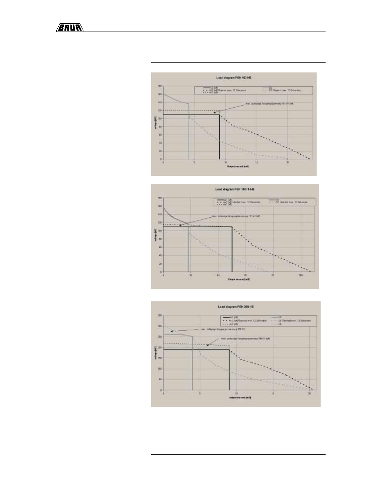
PGK output load curves
1-7
1. Product Information
1-8
1. Product Information
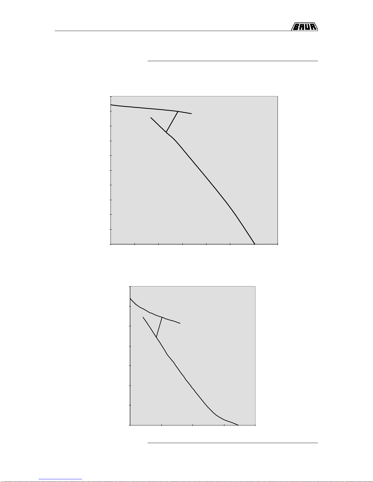
Load curve PGK 110 HB AC
1-8
Load curve PGK 110 HB DC
0
10
20
30
40
50
60
70
80
90
100
0 5 10 15 20 25 30 35
I / kV
U / kV
0
20
40
60
80
100
120
140
0 5 10 15 20
I / mA
U / kV
mA
1-9
1. Product Information
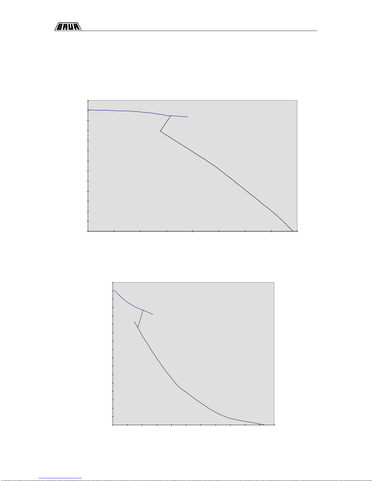
Load curve PGK 150 HB AC
LLoad curve PGK 150 HB DC
0
10
20
30
40
50
60
70
80
90
100
110
120
130
0 3 6 9 12 15 18 21 24
I / mA
U / kV
0
10
20
30
40
50
60
70
80
90
100
110
120
130
140
150
160
170
0246810121416182022
I / mA
U / kV

1-10
1. Product Information
0
20
40
60
80
100
120
140
160
180
200
220
0 5 10 15 20 25
I / mA
U / kv
Attention : maximum admissible
output voltage 190 kV rms.
Load curve PGK 260 HB DC
Load curve PGK 260 HB AC
0
20
40
60
80
100
120
140
160
180
200
220
240
260
280
300
320
0246810121416182022
I / mA
U / kV
Attention : maximum admissible
output voltage 260 kV

2. Packing and Shipping
Complains concerning damages should be made to us without
delay, using a standard transport damage claims form.
Confirmation of visible damage should immediately be obtained
from the carrier. The extent and probable cause of the damage
should be stated.
If damage is discovered during unpacking, contact the responsible
transportation company immediately. Request a written loss
assessment and make them responsible for the damage!
We also refer to the ‘General Terms of Sales and Delivery’ of:
The Test Sets ar shipped in robust cardboard cartons or in shipping
containers on wooden pallets. If the instruments are not used
immediately, always keep in the closed carton or shipping container
and store in dry rooms!
The H.V. unit may only be transported and operated vertically. It is
important that the tube is not bended so when packing in shipping
containers it may not be used as a support. For securing the H.V.
unit mounting holes are in the base plate.Additionally, the H.V. unit
can be also fasten to the potential grading ring. Please note that the
corona protection hood (with the exception of the PGK 70 HB) is
not a solid part but a hollow body filled partly with oil which must be
protected against impacts and collisions.
2. Packing and Shipping
Damage during transport
2-1
BAUR Prüf- und Messtechnik GmbH,
A-6832 Sulz /Austria

2. Packing and Shipping
○○○ ○○○○○○○○○○○○○○○○○○○○○○○○○○○○○○○○○○○
○○○○○○○○○○○○○○○○○○○○○○○○○○○○○○○○○○○○○○
○○○ ○○○○○○○○○○○○○○○○○○○○○○○○○○○○○○○○○○○
○○○ ○○○○○○○○○○○○○○○○○○○○○○○○○○○○○○○○○○○
○○○ ○○○○○○○○○○○○○○○○○○○○○○○○○○○○○○○○○○○
○○○○○○○○○○○○○○○○○○○○○○○○○○○○○○○○○○○○○○
○○○ ○○○○○○○○○○○○○○○○○○○○○○○○○○○○○○○○○○○
○○○ ○○○○○○○○○○○○○○○○○○○○○○○○○○○○○○○○○○○
○○○○○○○○○○○○○○○○○○○○○○○○○○○○○○○○○○○○○○
○○○ ○○○○○○○○○○○○○○○○○○○○○○○○○○○○○○○○○○○
○○○○○○○○○○○○○○○○○○○○○○○○○○○○○○○○○○○○○○
○○○○○○○○○○○○○○○○○○○○○○○○○○○○○○○○○○○○○○
○○○○○○○○○○○○○○○○○○○○○○○○○○○○○○○○○○○○○○
○○○ ○○○○○○○○○○○○○○○○○○○○○○○○○○○○○○○○○○○
○○○○○○○○○○○○○○○○○○○○○○○○○○○○○○○○○○○○○○
○○○○○○○○○○○○○○○○○○○○○○○○○○○○○○○○○○○○○○
○○○ ○○○○○○○○○○○○○○○○○○○○○○○○○○○○○○○○○○○
○○○○○○○○○○○○○○○○○○○○○○○○○○○○○○○○○○○○○○
○○○ ○○○○○○○○○○○○○○○○○○○○○○○○○○○○○○○○○○○
○○○○○○○○○○○○○○○○○○○○○○○○○○○○○○○○○○○○○○
○○○○○○○○○○○○○○○○○○○○○○○○○○○○○○○○○○○○○○
○○○○○○○○○○○○○○○○○○○○○○○○○○○○○○○○○○○○○○
○○○ ○○○○○○○○○○○○○○○○○○○○○○○○○○○○○○○○○○○
Notes
2-2

3. Placing into Operation
3-1
Subject Page
Connect to earth 3-2
Prepare test 3-2
Switch on 3-3
Switch off 3-4
EMERGENCY OFF 3-4
Change operating mode 3-5
3. Placing into Operation
Overview
In this section you will find all necessary information to put the High
Voltage Testing Sets PGK 70 HB, PGK 70 - 2,5 HB, PGK 110 HB,
PGK 150 HB and PGK 260 HB into operation.
This section contains the following subjects:

3. Placing into Operation
3-2
Connect to earth
It is absolutely necessary to connect the H.V. unit to earth and to
the test object via one of the two earthing screws on the base plate.
The earth lead should be as short as possible and must have a low
impedance (min. cross-section of 4 mm², copper).
••
••
•Isolate all connections from the test object, secure against
repeated switch-on and make sure that zero voltage condition
exists.
••
••
•Insulate nearby items which are under voltage.
!It must be assured that nearby items under voltage do
not result in breakovers or breakdowns, due to
applying the test voltage to the test object.
••
••
•Insert rectification resp. resistor bar (option with PGK 260 HB)
according to the desired operating mode.
••
••
•Connect operating unit and H.V. unit.
••
••
•Install H.V. connection to the test object.
••
••
•Connect instrument to mains according to specifications on type
plate.
••
••
•Turn variable transformer (11) to the left position.
••
••
•Set measuring range selector switch for the kV-meter (10) to „II“.
••
••
•Set measuring range selector switch for the mA-meter (8) to the
highest range in order to avoid damage to the instrument.
Short overloads (breakdowns and short-circuits at the test
object) are no danger to the mA-meter if ten times the value of
the relevant measuring range is not exceeded.
••
••
•Turn mode selector switch (9) to selected operating mode
(„+“, „-“ or „-“).
Prepare test
This manual suits for next models
4
Table of contents
Other Baur Test Equipment manuals


Popular Test Equipment manuals by other brands


Spinner
Spinner BN 533831 product manual

Circuit Specialists
Circuit Specialists TC-V2.12k user manual

GENERAL RADIO COMPANY
GENERAL RADIO COMPANY I559-B operating instructions

Zodiac
Zodiac PH Expert Instructions for installation and use

GE
GE Druck UPS-III user manual

Keysight
Keysight N1000A DCA-X Series quick start guide