TER T200PD User manual

This manual must be completed by the “CE Operating and service maual” Edition Rev. 02 30/03/2016
Edizione Rev. 02 30/03/2016
Questo manuale è integrato dal ”Manuale d’uso e manutenzione CE”
T200 PD T200 PD PFC
MANUALE PER OPERATORE OPERATING MANUAL

MANUALE PER OPERATORE OPERATING MANUAL
INDICE ARGOMENTI PAGINA
AVVERTENZA INIZIALE 4
DICHIARAZIONE DI CONFORMITÀ 5
PRECAUZIONI DI SICUREZZA 7
GENERALE 7
FUNZIONI E COMANDI 8
SALDATURA AD ELETTRODO 9
SALDATURA TIG 9
ISTRUZIONI 10
TABELLA MODI E REGOLAZIONI 16
ACESSORI OPZIONALI 20
FUNZIONI SPECIALI 21
DATI TECNICI T 200PD 22
DATI TECNICI T 200PD PFC 23
RICAMBI T 200PD 24
SCHEMA ELETTRICO T 200PD 25
RICAMBI T 200PD PFC 26
SCHEMA ELETTRICO T 200PD PFC 27
INDEX PAGE
WARNING 4
CONFORMITY DECLARATION 5
SAFETY PRECAUTIONS 7
GENERAL 7
OPERATION AND CONTROL 8
MMA MODE 9
TIG WELDING 9
INSTRUCTIONS 10
TABLE OF WORKING DATA MENU 16
OPTIONAL ACCESSORIES 20
SPECIAL FUNCTIONS 21
TECNICAL DATA T 200PD 22
TECNICAL DATA T 200PD PFC 23
SPARE PARTS T 200PD 24
ELETTRIC WIRING DIAGRAM T 200PD 25
SPARE PARTS T 200PD PFC 26
ELETTRIC WIRING DIAGRAM T 200PD PFC 27

MANUALE PER OPERATORE OPERATING MANUAL
WARNING
IMPORTANT: BEFORE STARTING THE EQUIPMENT, READ THE CONTENTS
OF THIS MANUAL, WHICH MUST BE STORED IN A PLACE FAMILIAR TO ALL
USERS FOR THE ENTIRE OPERATIVE LIFE-SPAN OF THE MACHINE.THIS
EQUIPMENT MUST BE USED ONLY FOR CUTTING OPERATIONS.
INTRODUCTION
To obtain the best performance from the machine and ensure the longest possible
life of all its components you must careffully follow the instructions for use and main-
tenance detailed in this manual. In the interest of our customers we suggest any
maintenance or repair of the equipment is made by qualied personnel.
All our products are subject to a constant development. We are therefore con-
strained to reserve the right to make any necessary or useful changes in design
and equipment.
ROUTINE MAINTENANCE
Prevent metal powder from accumulating inside the equipment. Disconnect the
power supply before every operation ! Carry out the following periodic controls
on the power source:
• Clean the power source inside by means of low-pressure
compressed air and soft bristel brushes.
• Check the electric connections and all the connection cables.
For the use and maintenance of the pressure reducers, consult the spe-
cic manuals.
AVVERTENZA INIZIALE
IMPORTANTE: PRIMA DELLA MESSA, IN OPERA DELL’APPARECCHIO LEGGERE
IL CONTENUTO DI QUESTO MANUALE E CONSERVARLO, PER TUTTA LA VITA
OPERATIVA, IN UN LUOGO NOTO AGLI INTERESSATI. QUESTO APPARECCHIO
DEVE ESSERE UTILIZZATO ESCLUSIVAMENTE PER OPERAZIONI DI SALDA-
TURA.
INTRODUZIONE
Per ottenere dall’impianto le migliori prestazioni ed assicurare alle sue parti la mas-
sima durata, è necessario attenersi scrupolosamente alle istruzioni per l’uso e alle
norme di manutenzione contenute in questo manuale.
Nell’interesse della clientela si consiglia di fare eseguire la manutenzione e, ove
occorra, la riparazione dell’impianto presso le ofcine della nostra organizzazione di
assistenza, in quanto provviste di appropriate attrezzature e di personale particolar-
mente addestrato.
Tutte le nostre macchine ed apparecchiature sono soggette ad un continuo sviluppo.
Dobbiamo quindi riservarci modiche riguardanti la costruzione e la dotazione.
MANUTENZIONE ORDINARIA
Evitare che si accumoli polvere metallica all’ interno dell’impianto. Togliere alimen-
tazione all’impianto prima di ogni intervento! Controlli periodici al
generatore:
• Effettuare la pulizia interna utilizzando aria compressa a bassa
pressione e pennelli a setola morbida.
• Controllare le connessioni elettriche e tutti i cavi di
collegamento.
Per la manutenzione e l’uso dei riduttori di pressione consultare i
manuali specici.
- 4 -
MANUALE PER OPERATORE OPERATING MANUAL
1. Dichiarazioni di conformità
TER SRL - Via Leopardi, 13 - 36030 Caldogno (VI) Italy
Dichiara che le macchine descritte in questo manuale devono es-
sere utilizzate in modo professionale ed in ambiente industriale.
Esse sono costruite in conformità alle direttive:
2014/35/EU (LDV) – 2014/30/EU (EMC) – 2002/95 (RoHs)
e alle seguenti norme armonizzate, se applicabili:
EN 60974-1 EN 60974-2 EN 60974-3 EN 60974-5 EN 60974-7
EN 60974-10 EN 60974-12
Date 30/03/2016 Maurizio Terzo
Direttore Generale
IN CASO DI CAT- TIVO
FUNZIONAMENTO RICHIEDETE L’ASSISTENZA DI
PERSONALE QUALIFICATO.
1. declaration of conformity
TER SRL - Via Leopardi, 13 - 36030 Caldogno (VI) Italy
declares that the machines descripted in this manual must be
use solely for professional purposes in an industrial environ-
ment and they are manufactured in compliance with the in-
structions contained in the harmonized standard:
2014/35/EU (LDV) – 2014/30/EU (EMC) – 2002/95 (RoHs)
and with the instructions c ontained in the harmonized
standard, if applicable:
EN 60974-1 EN 60974-2 EN 60974-3 EN 60974-5 EN 60974-7
EN 60974-10 EN 60974-12
Date 30/03/2016 Maurizio Terzo
General Manager
IN CASE OF BAD OPERATION YOU DEMAND THE ATTEN-
DANCE OF QUALIFIED STAFF.
Avvertenza : Questa apparecchiatura non è conforme alla normativa EN/IEC 61000-3-12. E’ respon-
sabilità dell’installatore o dell’utilizzatore (se necessario consultando il distributore della rete) as-
sicurarsi che l’apparecchiatura possa essere collegata ad una linea pubblica in bassa tensione.
The equipment don’t compiles with EN/ IEC 61000-3-12.
The installer or the user must be sure that it can be connected to the public low voltage power line,
if necessary, in consultation with the network distributor.
- 5 -

MANUALE PER OPERATORE OPERATING MANUAL
IMPORTANTE
PRIMA DELL’UTILIZZO DI QUESTO GENERATORE, LEGGETE ATTENTAMENTE
IL CONTENUTO DI QUESTO MANUALE; IL PRESENTE MANUALE DEVE ES-
SERE ARCHIVIATO IN LUOGO SICURO, NOTO ED ACCESSIBILE A TUTTI GLI
UTILIZZATORI DELLA MACCHINA PER TUTTO IL PERIODO OPERATIVO DELLA
STESSA. QUESTO GENERATORE DEVE ESSERE UTILIZZATO SOLO E SOL-
TANTO PER LAVORI DI SALDATURA.
1. Dichiarazione di conformità
Le macchine descritte in questo manualeT200PD / T200PD PFC, devono essere
utilizzate in modo professionale ed in ambiente possibilmente industriale. Esse
sono costruite in conformità alle normative standardizzate EN 60974-10 (compatibi-
lità elettromagnetica) e EN 60974-1.
In caso di mal funzionamente richiedete l’intervento di personale qualicato
1.1 Normative RAEE
Il simbolo riportato sull’imballo o sul prodotto indicano che lo stesso non può essere
smaltito come normale riuto domestico. La macchina deve essere consegnata
agli appositi punti di raccolta e/o operatori specializzati per lo smaltimento di riuti
elettrici/elettronici. Grazie ad un corretto smaltimento delle parti e componenti della
macchina potrete prevenire conseguenze negative per la salute ambientale ed
umana. Per informazioni più precise vi invitiamo a contattare gli Ufci preposti del
vostro Comune di residenza.
2. PRECAUZIONI DI SICUREZZA
L’arco elettrico generato in saldatura o taglio può essere dannoso per se stessi e
per gli altri. L’operatore deve pertanto essere ben informato ed istruito circa i rischi
e pericoli qui di seguito descritti e derivanti da operazioni di saldatura.
SHOCK ELETTRICO – Può essere fatale
Collegate la macchina all’impianto elettrico di alimentazione nel pieno ri-
spetto delle norme di sicurezza applicabili, assicurandovi preventivamen-
te che l’impianto stesso sia a norma e provvisto di messa a terra. Non
toccate a mani nude elementi conduttivi o potenzialmente conduttivi del-
la macchina, cavi ed elettrodi della stessa, ed evitate l’utilizzo di guanti
ed indumenti bagnati. Isolatevi dal pavimento e dal pezzo da saldare. Assicuratevi
di operare in un ambiente e posizione sicuri.
IMPORTANT
BEFORE STARTING THE EQUIPMENT, READ THE CONTENTS OF THIS MA-
NUAL, WHICH MUST BE STORED IN A PLACE FAMILIAR TO ALL USERS FOR
THE ENTIRE OPERATIVE LIFE-SPAN OF THE MACHINE.THIS EQUIPMENT
MUST BE USED SOLELY FOR WELDING OPERATIONS.
1. Conformity declaration
The machines descripted in this manual, T 200PD / T200PD PFC, must be
used solely for professional purposes in an industrial environment and they
are manufactured in compliance with the instructions contained in the harmo-
nized standard EN 60974-10 (electromagnetic compatibility) and EN60974-1.
In case of bad operation you demand the attendance of qualied staff.
1.1 RAEE Norm
The symbol on the product or on its packaging indicates that this product
may not be treated as household waste. Instead it shall be handed over to
the applicable collection point for the recycling of electrical and electronic
equipment. By ensuring this product is disposed of correctly, you will help
prevent potential negative consequences for the environment and human he-
alth, which could otherwise be caused by inappropiate waste handling of this
product. For more detailed information about recycling of this product, please
contact your local city ofce, your household waste disposal service or the
shop where you purchased the product.
2. SAFETY PRECAUTIONS
WELDING AND ARC CUTTING CAN BE HARMFUL TO YOURSELF AND
OTHERS. The user must therefore be educated against the hazards, summari-
zed below, deriving from welding operations.
ELECTRIC SHOCK – May be fatal.
Install and earth the welding machine according to the applicable
regulations. Do not touch live electrical parts or eletrodes with bare
skin, gloves or wet clothing. Isolate yourselves from both the earth
and the workpiece. Make sure your working position is safe.
- 6 -
MANUALE PER OPERATORE OPERATING MANUAL
FUMI E GAS – Possono essere dannosi per la salute
Mantenete il viso lontano dai fumi di saldatura ed evitate di respirarne
le esalazioni. Lavorate in ambiente correttamente ventilato e munitevi di
adeguate maschere e/o protezioni individuali ed aspiratori.
RAGGI ULTRAVIOLETTI ED INFRAROSSI - Possono danneggiare gli occhi e la pelle
Proteggete il viso ed occhi con maschere a lenti ltranti per saldatura, e
coprite mani e corpo con indumenti appropriati e sicuri. Garantite anche
la sicurezza altrui predisponendo schermi o tende protettive.
RISCHIO INCENDIO e BRUCIATURE
Gli spruzzi di saldatura possono essere fonte di incendio e bruciature alla
pelle. Assicuratevi pertanto di operare in ambiente privo di sostanze o
materiali inammabili ed indossate indumenti protettivi.
RUMORI
Questa macchina non produce rumori eccedenti gli 80dB. Nel caso si
consiglia l’utilizzo delle precauzioni previste dalle normative vigenti.
PACEMAKERS
Il campo magnetico generato nel processo di saldatura ad arco potrebbe in-
uenzare il funzionamento di eventuali pacemakers. I portatori di pacemakers
dovrebbero preventivamente consultare un medico e riceverne autorizzazio-
ne prima di operare.
ESPLOSIONI
Evitate di saldare in vicinanza di contenitori sotto pressione, polveri, fumi
o gas esplosivi o potenzialmente esplosivi. Bombole del gas e riduttori di
pressioni devono essere in perfetto stato e maneggiati con cura.
3. Generale
Questa macchina è un generatore di corrente continua, costruito per saldare mate-
riali conduttivi (metalli e leghe) mediante il processo di arco elettrico.
FUME AND GASES – May be hazardous to your health.
Keep your head away from fumes.
Work in the presence of adequate ventilation, and use ventilators
around the arc to prevent gases from forming in the work area.
ARC RAYS – May injure the eyes and burn the skin.
Protect yuor eyes with welding masks tted with ltered lenses, and
protect your body with appropiate safety garments.
Protect others by installing adequate shields or curtains.
RISK OF FIRE AND BURNS
Sparks (sprays) may cause res and burn the skin; you should the-
refore make sure there are no ammable materials in the area, and
wear appropriate protective garments.
NOISE
This machine does not directly produce noise exceeding 80dB. The
plasma cutting/welding procedure may produce noise levels beyond
said limit; users must therefore implement all precautions required
by law.
PACEMAKERS
The magnetic elds created by high currents may affect the operation of
pacemakers. Wearers of vital electronic equipment (pacemakers) should
consult their physician before beginning any arc welding, cutting, gouging
or spot welding operations.
EXPLOSIONS
Do not weld in the vicinity of containers under pressure, or in the
presence of explosive dust, gases or fumes. All cylinders and pres-
sure regulators used in welding operation should be handled with
care.
3. General description
This machine is a constant direct current power source, designed for welding
electrically conductive materials (metals and alloys) using the electical arc
- 7 -

MANUALE PER OPERATORE OPERATING MANUAL
POS. DESCRIZIONE DESCRIPTION
1 Interruttore Generale - ON/OFF Main Switch
2 presa di uscita positiva + Positive socket
3 presa pulsante torcia Tig e/o pedale Torch trigger socket and/or pedal
switch
4 raccordo uscita gas (1/4” G) - Gas outlet (1/4” G)
5 presa di uscita negativa - Negative socket
6 manopola regolazione corrente e parametri saldatura knob current set and welding
data
7 display LCD di visualizzazione - LCD display
8 tasto MODE :selezionatore modalita saldatura switch welding MODE
9 tasto CYCLE ig pulsato veloce switch CYCLE
10 tasto JOB switcj JOB
11 Tasto UP switch UP
12 tasto DOWN switch DOWN
1
2
3
4
5
6
7
8
9
10
11
12
- 8 -
FUNZIONI E COMANDI - OPERATION AND CONTROL
MANUALE PER OPERATORE OPERATING MANUAL
SALDATURA AD ELETTRODO (MMA)
•Collegare la pinza porta elettrodo e la pinza di massa alle polarità corrette, sulla
base delle speciche dell’elettrodo utilizzato.
•Selezionare il simbolo dell’ elettrodo con tasto “MODE ”
•Con il manopola di “REGOLAZIONE CORRENTE” impostare il livello corretto sul
display di visualizzazione della corrente; iniziare a saldare.
SALDATURA TIG
•Selezionare con tasto MODE la modalità TIG desiderata. Collegare la torcia alla
polarità negativa e il cavo con la pinza di massa alla polarità positiva.
•Collegate il tubo gas della torcia al raccordo uscita gas.
•Collegare la spina della torcia alla “Presa Pulsante Torcia Tig” (rif: n°3 img. pag. 3).
•Collegare la bombola del Gas (ARGON) al raccordo di entrata Gas
(portata 5/9 lt/min).
•Con il Potenziometro di regolazione corrente impostare il valore desiderato.
MMA MODE:
•Connect the electrode holder and the earth clamp plugs to the correct ma-
chine polarities, according to the electrode manufacturer specs.
•Select “STICK” mode by MODE switch.
•Turning the “CURRENT KNOB”, adjust the displayed current level and
weld.
TIG WELDING
•Select the by MODE switch “TIG” mode. Connect the torch to the negative
polarity and the earth clamp to the positive one.
•Connect the torch gas hose to the machine gas outlet.
•Connect the torch trigger plug to the “Torch trigger socket” (ref. pict. 3
pag. 3).
•Connect the gas bottle (ARGON) hose to the machine gas inlet nipple.
•Turning the current knob adjust your current level.
- 9 -
MANUALE PER OPERATORE OPERATING MANUAL
ISTRUZIONI
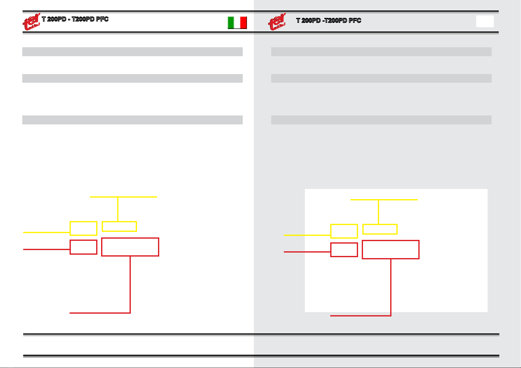
Il pannello ha 5 tasti, un display e un encoder dotato di switch.
TASTO MODE
Tasto MODE, seleziona la modalità di saldatura tra:
STICK – TIG STD - TIG PULSE – TIG MIX
la modalità di saldatura è indicata nella parte alta del display.
TASTO CYCLE
Tasto CYCLE, solo nelle varie modalità TIG, seleziona il ciclo di saldatura tra:
2 TEMPI - 2 TEMPI CON RAMPA DI FINALE
4 TEMPI – 4 TEMPI CON RAMPA INIZIALE E FINALE
SPOT – SPOT CON RAMPA FINALE
il ciclo di saldatura è indicato nella parte centrale del display e visualizzato graca-
mente.
TASTO MODE
MODALITÀ DI SALDATURA
TASTO CYCLE
CICLO DI SALDATURA
SWITCH MODE
WELDING MODE
SWITCH CYCLE
WELDING CYCLE
INSTRUCTIONS
The control panel has 5 switches, one LCD display and one encoder with switch,
MODE SWITCH
MODE push button, select the welding mode : STICK – TIG STD - TIG PULSE –
TIG MIX The welding modality is shown on the top side of display.
CYCLE SWITCH
CYCLE push button, it works only in TIG mode, it is used to select the cycle of
welding.
2 TIMES – 2 TIMES WITH CRATERFILLER
4 TIMES - 4 TIMES WITH UP SLOPE AND CRATERFILLER
SPOT – SPOT WITH CRATERFILLER
The welding cycle is indicated in the middle display by graphic symbols
- 10 -

MANUALE PER OPERATORE OPERATING MANUAL
ENCODER
Girando l’encoder imposto il set di corrente. Quando cambio il set di corrente per
alcuni secondi compare sul display l’indicazione dello spessore consigliato del ma-
teriale da saldare relativo a quel set.
PARAMETRI PRINCIPALI
Premendo l’encoder sul display compare il parametro principale che può essere
modicato.
Il parametro che compare dipende dalla modalità e dal ciclo impostati; il parametro
può essere uno solo o possono essercene più d’uno, usa i tasti contraddistinti con
le freccie per spostarre la regolazione tra i parametri oppure premi l’encoder per
ritornare alla regolazione principale.
VRD on : premendo tasto encoder per 5 sec si attiva/disattiva VRD
ENCODER
- 11 -
ENCODER
Rotate it, to set the output current.
When the set is modied, the display show for a few second the suggested thick-
ness of the welding material that can be weld with the current set.
MAINS PARAMETER
Push the encoder, the data that can be modied is displayed.
The data is displayed in graphic mode.
Rotate the encoder to change the data.
The data shown depends from the selected welding cycle. The data can be single
or multiple, use the side arrow push buttons to select more parameters or push the
knob to return to the main current set
VRD on : press the encoder for 5 sec. to enable/disable Voltage Reduction Device
ENCODER
MANUALE PER OPERATORE OPERATING MANUAL
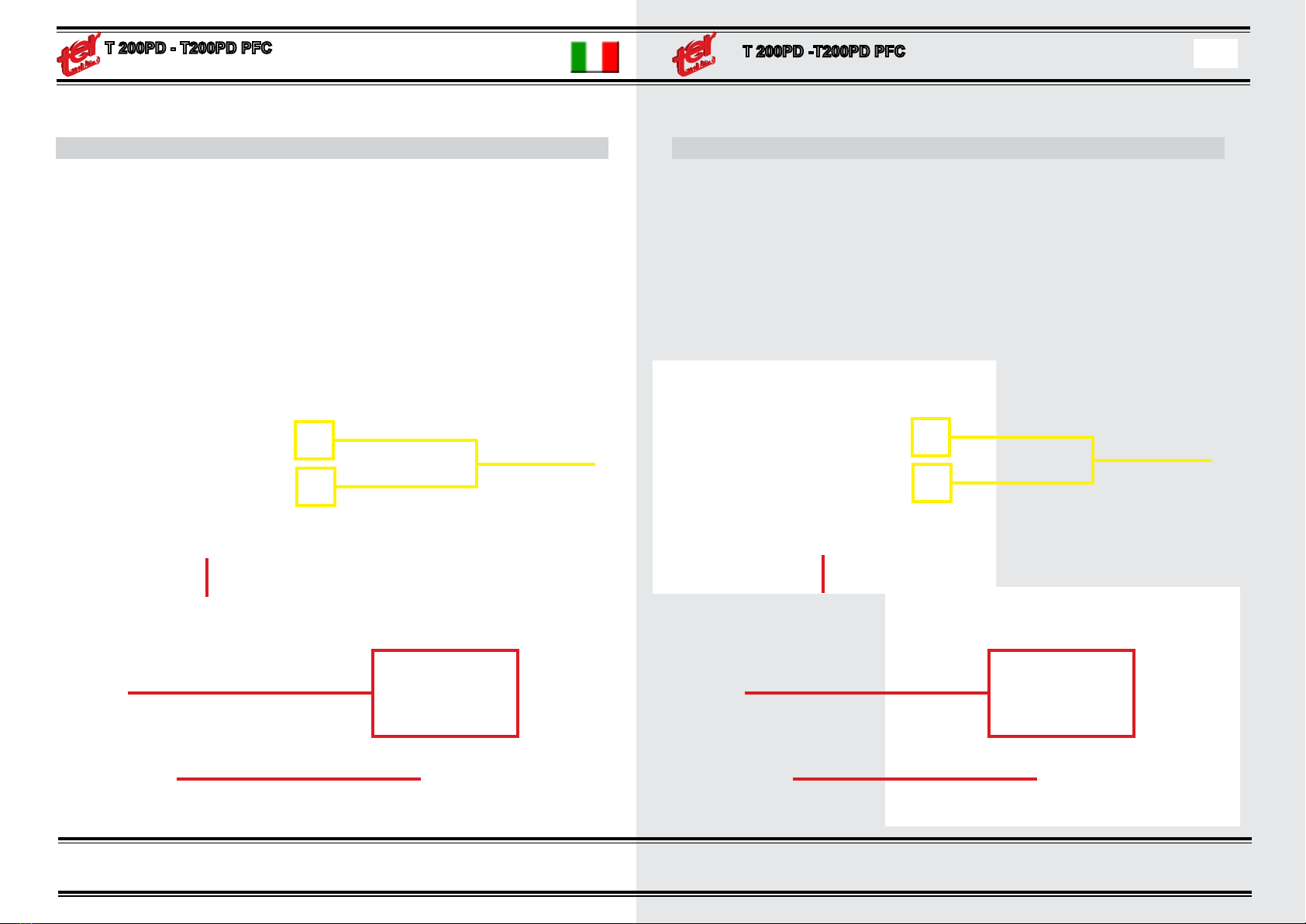
MENU’ PARAMETRI:
Premendo i tasti SU e GIU tutti i dati di lavoro possono essere selezionati e rego-
lati. Quando si preme uno di questi pulsanti, il display mostra un’elenco di righe,
ogni riga ha un parametro di saldatura che può essere regolato. Questi parametri
dipendono dalla modalità di saldatura selezionato.
Con i due pulsanti su e giù, è possibile scegliere il parametro che deve essere
cambiato. I dati selezionati vengono visualizzati in nero, utilizzare la manopo-
la principale per cambiare i dati. Il menu di impostazione scompare e il display
ritorna al menu principale dopo 10 secondi dall’ultima pressione di un pulsante di
comando o l’ultima regolazione tramite la manopola.
È anche possibile tornare al menu principale premendo la manopola.
- 12 -
TASTO UP
TASTO DOWN
SELEZION-
ARE PARA-
RUOTARE ENCODER PER MODIFICARE PARAMETRO
LISTA PARAMETRI
PER USCIRE DALLA LISTA PARAME-
TRI PREMERE ENCODER
MAIN MENU:
By pushing the push buttons UP and DOWN all working data can be selected and
adjusted. When one of these push button is pressed, the display shows the list of
rows, each row has a welding parameter that can be adjusted. These parameters
depend from the selected welding modality.
With the two push buttons UP and Down, it is possible to choose the parameter
that need to be changed. The selected data are shown in black, use the main
knob to change the data. The parameters setting menu disappear and the
display returns to the main menu after 10 seconds from the last pressure of one
push button or last adjustment by the knob.
It is also possible to return to the main menu by pressing the knob.
UP SWITCH
DOWN SWITCH
PARAMETER
SELECTION
TURN ENCODER TO CHANGE PARAMETER
LIST OF PARAMETERS
TO EXIT THE PRESS LIST
PARAMETERS ENCODER

MANUALE PER OPERATORE OPERATING MANUAL
TASTO JOB
Questa funzione è attiva solo nella modalità TIG.
Posso uscire da questo menù ripremendo il tasto JOB.
Tramite questo menù è possibile memorizzare tutti i parametri impostati o richia-
mare un’impostazione precedentementa salvata.
I job sono in tutto 10 e contengono la modalità, il ciclo, il set di corrente e tutti i
parametri.
Ad ogni job è possibile associare un nome, nel momento in cui lo si salva, il che
facilita poi il riconoscimento dello stesso.
Nel menù job i tasti a destra e a sinistra del display acquisiscono la funzione che
viene indicata in anco al tasto stesso.
Nella prima schermata del menù job devo scegliere se salvare o richiamare un
job; premo il tasto MODE per salvare le impostazioni in un nuovo job o premo il
tasto CYCLE per uscire dalla funzione JOB.
- 13 -
JOB PUSH BUTTON.
It works only in TIG mode.
Press JOB push button to enter in JOB menu. Press JOB push button again to
return to the main menu.
By JOB menu it is possible to memorize or recall the working session.
The JOBS are 10 and the complete welding session can be stored in any of
these JOBS (the session includes: the cycle mode, the cycle set, current set and
all working data).
It is possible save the JOB with a nick-name.
In the JOB menu the right side push buttons becomes the function as the graphic
symbol beside them indicates.
In the rst page of JOB menu can be selected the saving or the recalling of the
JOBS, use the push button indicated by the graphic display to select one of the
two operations.
To exit from the JOB menu without any saving or recall operation, push the push
button CYCLE.

MANUALE PER OPERATORE OPERATING MANUAL
ESEMPI TASTO JOB
Esempio 1:
Salvataggio dei parametri in un job:
- entro nel menù job premendo il tasto JOB;
- premo il tasto MODE (SAVE CONTEST IN JOB);
- tramite i tasti UP e DOWN seleziono il numero del job; se il job è libero compare
la scritta Free, altrimenti compare il nome che è stato precedentemente associato
a quel job.
- premo nuovamente il tasto MODE;
- scrivo il nome da associare al job: seleziono il carattere girando l’encoder e mi
sposto di carattere coi tasti di destra;
- premo nuovamente il tasto MODE per completare la sequenza di salvataggio.
Esempio 2:
Richiamo di un job:
- entro nel menù job premendo il tasto JOB;
- premo il tasto CYCLE (LOAD JOB);
- tramite i tasti UP e DOWN seleziono il job; se il job non è stato utilizzato com-
pare la scritta No job, altrimenti compare il nome che è stato precedentemente
associato a quel job.
- premo nuovamente il tasto CYCLE, la nuova sessione di lavoro appare sul dis-
play.
- 14 -
JOB SWITCH EXAMPLE
Example 1:
Save data in a JOB
-press push button JOB to enter in the job menu
-press the push button MODE (SAVE SESSION IN JOB)
-Pushing the push button UP and DOWN select the number of the JOB.
If this the JOB is empty, it will be shown with word “free”, instead, if the JOB is full,
the display shows the name of this job.
-To go on with the storing sequence, push again MODE push button.
-Write the nick name of the new job, by selecting character by character by rotat-
ing encoder and selecting by the right side push buttons.
-push MODE push button to complete the Job saving sequence;
Example 2:
Recall of a stored JOB:
-press push button JOB to enter in the job menu
-Select the recall of the JOB by pressing the push button CYCLE
Push the push button UP or DOWN to select the JOB.
If this the JOB is empty, it will be shown with word “no job”, instead, if the JOB is
full, the display shows the nick name used when the Job was stored.
-press CYCLE push button to exit and the new session of JOB N° xx appears in
the display
MANUALE PER OPERATORE OPERATING MANUAL
SPIEGAZIONE PARAMETRI
Arcforce: è la percentuale di corrente che viene aggiunta quando l’elettrodo va
in corto sul pezzo.
Pregas: tempo in secondi e decimi tra l’attivazione dell’elettrovalvola e dell’inverter
Postgas: tempo in secondi e decimi tra lo spegnimento dell’inverter e la chiusura
dell’elettrovalvola
I Start: valore della corrente di partenza in percentuale sul valore di set
Up Slope: in secondi e decimi, durata della rampa iniziale
Down Slope: in secondi e decimi, durata della rampa di chiusura
I Stop: valore della corrente di chiusura in percentuale sul valore di set
HF: imposto la partenza con alta frequenza (HF ON) o in LIFT (HF OFF)
Time Spot: tempo di saldatura in secondi e decimi
Glick: nelle modalità a 4 tempi se durante la saldatura do un impulso breve
al pulsante della torcia la corrente si porta al valore ridotto selezionato, con un
nuovo breve impulso la corrente torna al valore impostato.
Il Glick è selezionato nel menu parametri tra i valoti 25%, 50%, 75% e OFF.
Il valore selezionato del glick è relativo al valore in percentuale della corrente di set.
Frequenza: in hertz e decimi la frequenza di pulsazione in pulsato (presente solo
in TIG PULSATO)
Balance: pecentuale di corrente al valore alto rispetto al tempo totale di impulso
(presente solo in TIG PULSATO)
I Low: valore percentuale della corrente bassa rispetto al valore di corrente alta
(presente solo in TIG PULSATO)
Softness: forma d’onda squadrata o sinusoidale (presente solo in TIG PULSA-
TO)
Frequenza mix: frequenza in hertz e decimi dei pacchetti di impulsi
Balance mix: ampiezza del pacchetto di impulsi
- 15 -
SUMMARY INFORMATION OF WORKING DATA
Arcforce: it is the added current when the electrode is touch the working piece
(short circuit). The added value is in % of the set current.
Pregas: time to start gas before start welding.
(seconds)
Postgas: time to stop gas after stop welding.
(seconds)
I Start: value of the starting current, % refers to the set value.
Up Slope: duration of the initial slope.
(seconds)
Down Slope: duration of the nal slope. (seconds)
I Stop: value of the stop current, % refers to the set value.
HF: set the striking of the arc by high frequency (HF ON), or LIFT ARC (HF OFF)
Time Spot: time of welding spot in seconds,
Glick: this function is available only in 4 times mode. It is possible during the
welding by a quick pressing the torch switch, to drop down the current at the
reduced value ( glick value), a new quick pressure of the torch switch again the
torch switch to return at the set current.
The selection of the Glick value is in the parameter menu.
It can be selected between 25%, 50%, 75% and “OFF”.
Frequency: it is the pulsed frequency in Hertz, (this set is only when cycle PULSE
TIG is used)
Balance: % of the current at the hight value ref to the total time of pulse.(this set
is only when cycle PULSE TIG is used)
I Low: value of current lower than the current high.(this set is only when cycle
PULSE TIG is used)
Softness: wave form square or sinusoidal.
(this set is only when cycle PULSE TIG is used)
Frequenza mix: frequency of the pulse, in Hertz.
Balance mix: width of pulses
MANUALE PER OPERATORE OPERATING MANUAL
- 16 -- 16 -
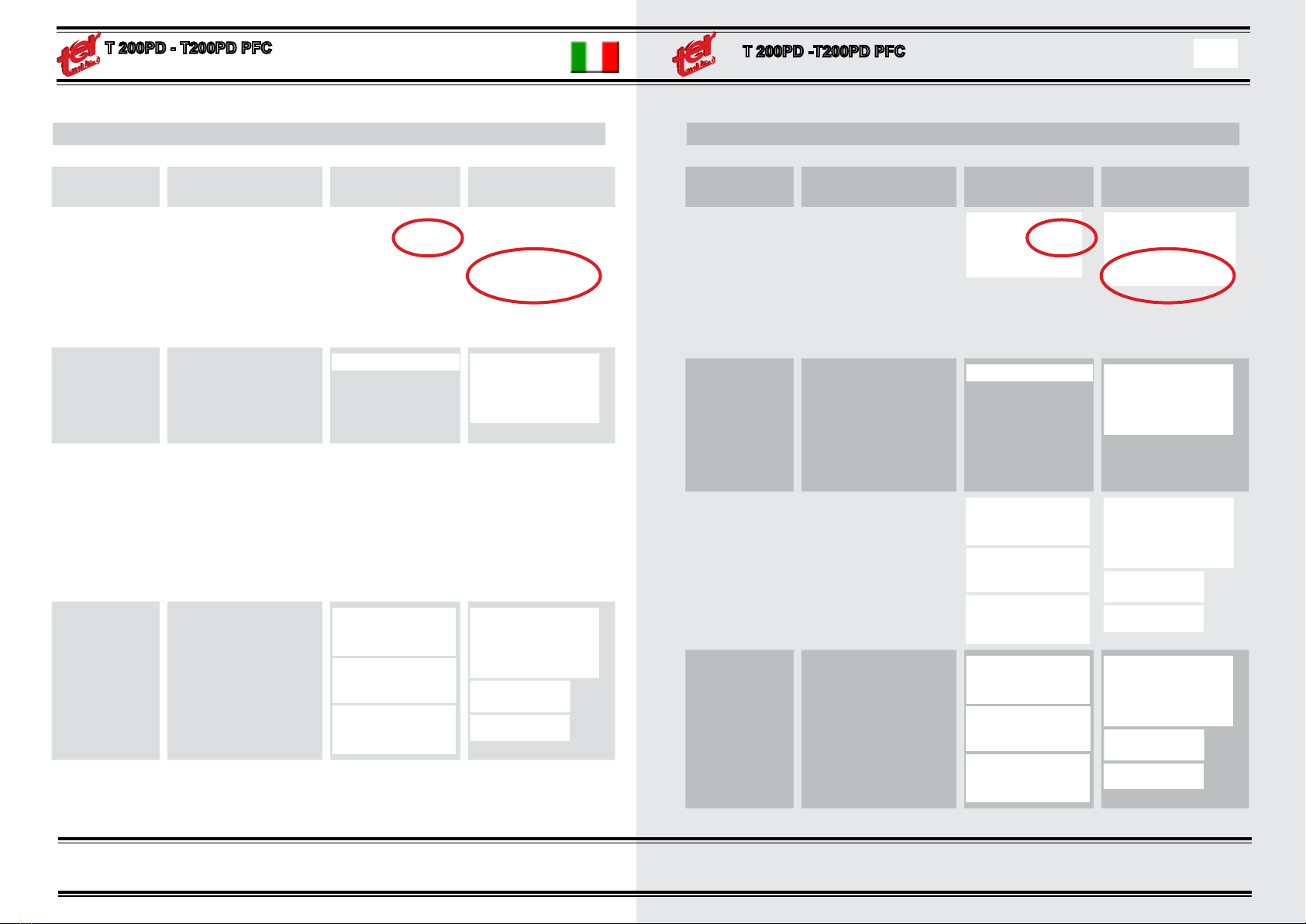
TABELLA MODI E REGOLAZIONI
DATO DESCRIZIONE VISUALIZZAZIONE
ANALOGICA
VISUALIZZAZIONE
GRAFICA
ELETTRODO Funzione Elettrodo.
Può essere selezionato
VRD. Visualizza lo STAND
BY. Nella parte alta c’è il set
di corrente, mentre in quella
bassa c’è lo spessore con-
sigliato
Thickness, VRD,
Stand by
ARCFORCE Funzione solo in Elettrodo.
E’ la corrente aggiunta
durante il corto circuito
dell’elettrodo. E’ espressa
in % del set.
Premi la manopola per
la funzione
MODE
TIG STD
Standard TIG, può essere
in: HF start or LIFT ARC
start GLICK on/off nel sotto
menù.
Cycle: 2T-4T -Timer con i
Pulsanti di ciclo
MODE
TIG PLS
Pulse Tig, può essere in:
HF start or LIFT ARC start
GLICK on/off nel sotto
menù.
Cycle: 2T-4T -Timer con i
Pulsanti di ciclo
- 16 -- 16 -
TABLE OF WORKING DATA MENU
DATA DESCRIPTION ANALOG SET GRAPHIC SET
ELECTRODE
Electrode function,
can be in VRD
can be in stand by STD-
BY
Upper data is SET Current
Bottom data suggested
thickness
Thickness, VRD,
Stand by
ARCFORCE Only in ELECTRODE
it is the added current
when the electrode is touch
the working piece (short cir-
cuit). The added value is in
% of the set current.
Premi la manopola per
la funzione
MODE
TIG STD
Standard TIG, can be in:
HF start or LIFT ARC start
GLICK on/off
Cycle: 2T-4T -Timer
MODE
TIG PLS
Standard TIG, can be in:
HF start or LIFT ARC start
GLICK on/off
Cycle: 2T-4T -Timer
MANUALE PER OPERATORE OPERATING MANUAL
TABELLA MODI E REGOLAZIONI
DATO DESCRIZIONE VISUALIZZAZIONE
ANALOGICA
VISUALIZZAZIONE
GRAFICA
MODE
TIG MIX
MIX Tig, può essere in:
HF start or LIFT ARC start
GLICK on/off nel sotto menù
Cycle: 2T-4T -Timer con i
Pulsanti di ciclo
PREGAS Tempo del pre gas prima
dell’inizio della saldatura
UP SLOPE Tempo della rampa di sali-
ta/discesa tra la corrente di
start e quella di set.
I START Tempo della rampa di disc-
esa tra la corrente di salda-
tura e la corrente nale.
DOWNSLOPE Tempo della rampa di disc-
esa tra la corrente di salda-
tura e la corrente nale.
I STOP Valore della corrente nale,
espressa in % del set cor-
rente principale.
POST GAS Tempo del post gas alla
ne della saldatura.
TABLE OF WORKING DATA MENU
DATA DESCRIPTION ANALOG SET GRAPHIC SET
MODE
TIG MIX
MIX Tig, can be in:
HF start or LIFT ARC start
GLICK on/off
Cycle: 2T-4T -Timer
Mix Arc after Up slope
PREGAS Time of the pre-gas before
start welding.
UP SLOPE Time of the growth of the
current from I start to I set
( welding current)
I START value of the starting cur-
rent, % refers to the set
value.
DOWNSLOPE Time of the slowing down
of the current from SET
vaule to stop current
I STOP value of the stopping cur-
rent, % refers to the set
value.
- 17 -- 17 -

MANUALE PER OPERATORE OPERATING MANUAL
TABELLA MODI E REGOLAZIONI
DATO DESCRIZIONE VISUALIZZAZIONE
ANALOGICA
VISUALIZZAZIONE
GRAFICA
HF ON/OFF Selezione del tipo di innes-
co tra HF e lift arc
GLICK Selezione del Glick tra
spento (OFF) e i livelli 25%;
50%; 75%.
Quando il pulsante è pre-
muto per un breve tempo
(glick), la correne scende al
livello Glick e risale al pros-
simo glick.
FREQUENCY Regolazione della Fre-
quenza della pulsazione
Tig.
Questa regolazione è attiva
solo in modalità TIG PULS
BALANCE Regolazione del rapporto
corrente alta- corrente bas-
sa della TIG PULSATO.
Questa regolazione è attiva
solo in modalità TIG PULS
I LOW Regolazione del livello
basso della corrente del
TIG PULSATO, espressa
in % del set corrente,
Questa regolazione è
attiva solo in modalità TIG
PULS
TABLE OF WORKING DATA MENU
DATA DESCRIPTION ANALOG SET GRAPHIC SET
HF ON/OFF Selection between HF strik-
ing of lift arc striking
GLICK Selection between Glick
levels: OFF, 25%, 50%,
75%
The Glick is activated by
short command of the torch
switch
FREQUENCY Frequency adjustment.
Available only in PULS TIG
modality.
BALANCE Adjustment of the balance
between high and low cur-
rent.
Available only in PULS TIG
modality.
I LOW Adjustement of the low
lewel of current during the
pusation.
Available only in PULS TIG
modality.
- 18 -- 18 -

MANUALE PER OPERATORE OPERATING MANUAL
TABELLA MODI E REGOLAZIONI
DATO DESCRIZIONE VISUALIZZAZIONE
ANALOGICA
VISUALIZZAZIONE
GRAFICA
SOFTNESS Il Softness del pulsato rego-
la la velocità dello sposta-
mento della corrente tra il
valore Ilow e il valore di set
corrente.
Questa regolazione è attiva
solo in modalità TIG PULS
FREQENZA MIX
(ARCO VIBRA-
TO)
Frequenza di ripetizione
della vibrazione dell’arco.
Questa regolazione è attiva
solo in modalità TIG MIX.
BAL. MIX Regolazione del tempo di
vibrazione rispetto al tempo
di saldatura normale.
Questa regolazione è attiva
solo in modalità TIG MIX.
TABLE OF WORKING DATA MENU
DATA DESCRIPTION ANALOG SET GRAPHIC SET
SOFTNESS Transient speed between I
low and I Set.
Available only in PULS TIG
modality.
FREQENZA MIX Frequency of the high fre-
quency arc modulation.
Available only in MIX TIG
modality.
BAL. MIX Balance between the high
frequency arc modulation
and standard dc current.
Available only in MIX TIG
modality.
- 19 -- 19 -
MANUALE PER OPERATORE OPERATING MANUAL
ACCESSORI OPZIONALI
PINZA DI MASSA
completa di 3 m. cavo 35 mmq. e spina.
TORCIA STANDARD TIG 17
TORCIA STANDARD TIG 26 SP
Torcia Tig con pulsante ON - OFF, lunghezza 4 m. , completa di raccordo gas da
¼ , spina ed accessori da 2,4 mm. montati.
PRESETTA FEMMINA 5 POLI
PEDALE
Sul connettore 5 poli è possibile collegare un comando a distanza a pedale, il
corretto collegamento viene visualizzato sul display dalla scritta PEDAL seguita
dall’indicazione OFF/ON e da un disegno che indica all’incirca la posizione del
pedale. Quando si usa un pedale il ciclo viene impostato in automatico su 2T.
Sul display compare l’indicazione del set massimo di corrente, quando sono in
saldatura il display indica la corrente relativa alla posizione del pedale, la cor-
rente va da un minimo pari ad un quarto del valore impostato no al massimo al
valore impostato.
Se quindi imposto 100A la regolazione varia da 25 a 100A. Se imposto 200A la
regolazione minima sarà di 50A.
TORCIA DIGITALE
Sull’attacco torcia 5 poli è possibile collegare una torcia digitale che, oltre ad
avere il pulsante di inizio/ne ciclo ha 2 pulsanti up/down per la regolazione del
set di corrente.
La presenza della torcia digitale viene visalizzata sul display da una doppia frec-
cia vicino al set di corrente.
- 20 -
OPTIONAL ACCESSORIES
CLAMP MASS
Complete 3 m. 35 mmq cable. and plug.
TORCH STANDARD TIG 17
TORCH STANDARD TIG 26 SP
TIG torch with ON - OFF button, length 4 m. Complete with tting ¼ gas, plug
and accessories 2.4 mm. mounted.
FEMALE SOCKET 5 POLE
PEDAL
It is possible to connect the pedal remote control on the 5 poles front connector.
The connection of the pedal is displayed in the display by graphic symbol, and
with the indication PEDAL ON/OFF.
When a pedal is connected to the ve pole receptacle, the torch switch cycle
is automatically set in 2T mode. In OFF mode, the display shows the set of the
current adjusted by the main knob. While, during the welding, the display shows
the current depending from the pedal position and the current set with the knob.
The adjustement by the pedal is :
Min current = max set current / 4
Max current = set current by the main knob
Example 1 : if the set current is 100A the setting by pedal will be from 25A to 100A.
Example 2 : if the set current is 200A the setting by pedal will be from 50A to 200A.
DIGITAL TORCH
It is possible to connect a digital tig torch in the 5 poles front connector.
The digital torch has one switch to command the welding, and two switches to
adjust the current up and down. The connection of the digital torch is showed in
the display by a double arrows beside the value of the adjusted current.
At any shot of the switch up and down, the current is increased or decreased by 1A.
If the switches up or down are held pushed, the current rapidly changes up or down.
This manual suits for next models
3
Table of contents
Other TER Welding System manuals


Popular Welding System manuals by other brands

Lincoln Electric
Lincoln Electric POWER WAVE 11124 Operator's manual

Hyundai
Hyundai MMA-160 user manual

Lincoln Electric
Lincoln Electric PRO-CUT IM665 Operator's manual

Cebora
Cebora SOUND MIG 2035/M Pulse Service manual

Miller Electric
Miller Electric Gas Cylinder Rack owner's manual

Polyvance
Polyvance 6085-C quick start guide


Lincoln Electric
Lincoln Electric POWER WAVE 355/405 SVM159-A Service manual

Miller
Miller Spectrum 875 Auto-Line owner's manual

TECNA
TECNA TE550 instruction manual

Sweiss
Sweiss SKYTIG 2045 ACDC Operator's manual

Magmaweld
Magmaweld COMPACT SMART Series user manual

Thermal Dynamics
Thermal Dynamics CUTMASTER operating manual