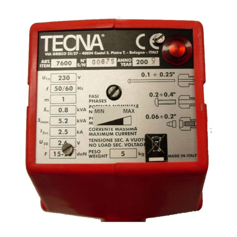
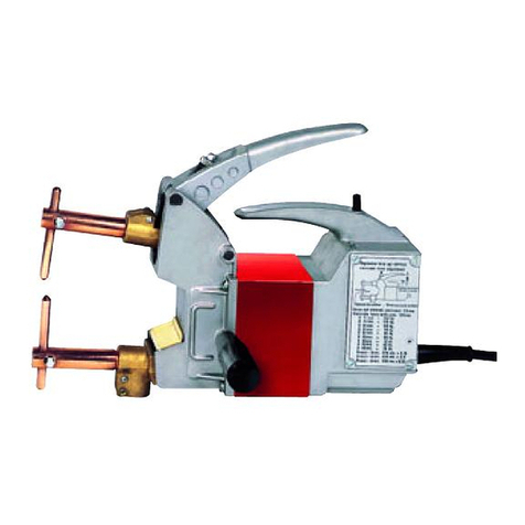
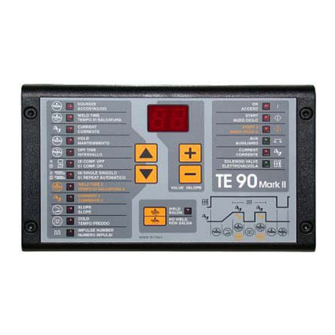
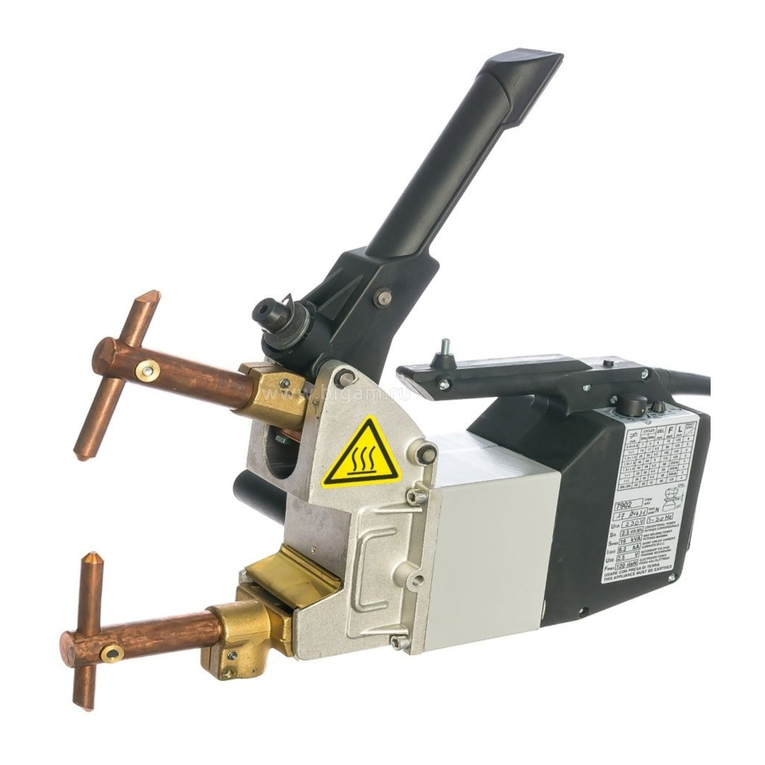
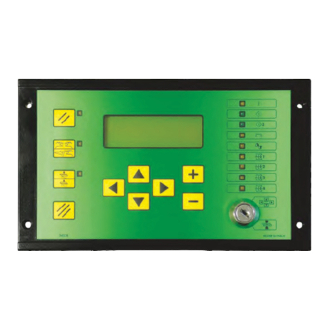
TECNA TE550 User manual

Instruction manual ITEM TE550 S.p.A.
2/92
This page intentionally left blank

S.p.A. ITEM TE550 Instruction manual
3/92
TABLE OF CONTENTS
CHAPTER 1 - TE550 WELDING CONTROL UNIT DESCRIPTION ........................................ 6
1.1 - MAIN TECHNICAL FEATURES.............................................................................. 6
1.2 - COMMANDS ON THE PANEL................................................................................ 7
1.3 - PANEL LEDs .......................................................................................................... 8
1.4 - DESCRIPTION OF THE DISPLAYED INFORMATION .......................................... 9
1.5 - CONTROL UNIT SWITCH-ON.............................................................................. 14
CHAPTER 2 - CONTROL UNIT PROGRAMMING................................................................ 15
2.1 - PROGRAM DATA................................................................................................. 16
2.2 - PERCENTAGE ADJUSTMENT OPERATING MODE .......................................... 17
2.3 - CONSTANT CURRENT OPERATING MODE ...................................................... 20
2.4 - CONSTANT ENERGY OPERATING MODE......................................................... 23
2.5 - WORKING PROGRAM PARAMETERS DESCRIPTION...................................... 26
2.6 - SETUP MENU ....................................................................................................... 34
2.7 - STEPPER MENU .................................................................................................. 36
2.8 - CURRENT STEPPER FUNCTION ........................................................................ 38
2.9 - FEATURES MENU................................................................................................ 43
2.10 - PROGRAM COPY............................................................................................... 48
2.11 - CHECK INPUT .................................................................................................... 49
2.12 - PROG. SEQUENCE ............................................................................................ 50
2.13 - TIP-DRESSING ................................................................................................... 53
2.14 - THICKNESS SENSOR........................................................................................ 57
2.15 - ADJUSTING THE FIRST INSERT DELAY ......................................................... 60
CHAPTER 3 - SEAM WELD WORK MODE.......................................................................... 61
CHAPTER 4 - BUTT WELD WORK MODE........................................................................... 64
CHAPTER 5 – SER. SPOT MODE........................................................................................ 67
CHAPTER 6 - CASCADE WORK MODE.............................................................................. 68

Instruction manual ITEM TE550 S.p.A.
4/92
CHAPTER 7 - THE WORK CYCLE ....................................................................................... 69
CHAPTER 8 - STOP BAD SPOTS ........................................................................................ 70
CHAPTER 9 - WELDS COUNTER FUNCTION..................................................................... 72
CHAPTER 10 - DESCRIPTION OF THE INTERFACE OUTPUTS........................................ 73
10.1 - WELD ERROR (WRONG)................................................................................... 73
10.2 - END CYCLE ........................................................................................................ 75
10.3 - LOCK................................................................................................................... 75
CHAPTER 11 - SELECTING THE WORK PROGRAM THROUGH EXTERNAL RECALLS 76
CHAPTER 12 - DOUBLE STROKE FUNCTION.................................................................... 77
CHAPTER 13 - OPTIONS...................................................................................................... 78
13.1 - RS-232 SERIAL INTERFACE ............................................................................. 78
13.2 - RS-485 SERIAL INTERFACE ............................................................................. 80
13.3 - INTERFACE FOR PROPORTIONAL VALVE ..................................................... 81
13.4 - INTERFACE FOR PRESSURE SENSOR ........................................................... 82
CHAPTER 14 - DESCRIPTION OF THE SIGNALS ON THE TERMINAL BOARD............... 84
14.1 - DESCRIPTION OF THE SIGNALS ON THE OPTIONAL BOARDS 50200 OR
50189............................................................................................................................. 86
CHAPTER 15 - LIST OF TE550 MESSAGES ....................................................................... 87
15.1 - SYSTEM ERRORS.............................................................................................. 87
15.2 - WORK ERRORS ................................................................................................. 88
15.3 - PROGRAMMING ERRORS ................................................................................ 91
CHAPTER 16 - TECHNICAL SPECIFICATIONS .................................................................. 92

S.p.A. ITEM TE550 Instruction manual
This page intentionally left blank
The information contained in this document is subject to modification without notice.
No part of this document can be either reproduced or transferred in whatever format neither by electronic nor by mechanic
means for whatever purpose, without ’s written permission.
is a registered brand.
5/92

Instruction manual ITEM TE550 S.p.A.
CHAPTER 1 - TE550 WELDING CONTROL UNIT DESCRIPTION
The TE550 is a microprocessor-based welding control unit for resistance welders. The task of
the welding control unit is to manage the welder components, in particular the controlled
diodes that carry out the welding current adjustment.
The TE550 is a particularly versatile welding control unit as it can be adjusted to different
types of welders; it may be installed not only on spot and projection welders but on seam
welders too. It may work with power adjustment: both in constant current and in constant
energy (optional). The number of inputs and outputs may be increased so to better adjust the
welding control unit to automatic machines.
It is possible to store up to 250 different welding programs, 127 of which are recalled directly
from an external device. Each program comprises several programmable parameters that
describe the work cycle. In addition to the plain 4-stage welding cycle, the control unit allows
the running of welding processes with pre-welding current, post-welding current, slope and
pulses.
1.1 - MAIN TECHNICAL FEATURES
Simplified programming via 6 keys and a backlit alphanumeric LCD.
Synchronous control with controlled diodes, phase control current adjustment.
Storage of 250 welding programs, 127 recallable from an external drive.
Up to 33 programmable parameters for each program.
Slope, pulses, pre-weld, post-weld functions and adjustment of the welding times in half-cycles.
Display of the RMS welding current measurement in kA and relative angle of conduction.
3 operating modes: standard, constant current and constant energy (optional).
Weld current, conduction angle, thickness and material indentation limits (optional), on the cylinder
pressure detected by an external sensor (optional).
Double stroke function.
Stepper function to compensate the electrodes wear with programmable curve.
Single and automatic cycle. WELD and NO-WELD function.
Adjustment of first insertion delay.
Control of 5 solenoid valves 24 VDC max. 5 W with self-protected output.
Self-adjustment at mains frequency 50/60 Hz.
Serial data transmission by means of optional insulated RS232 or RS485 ports.
Output for proportional solenoid valve.
Key for selecting foot control or two-hand control.
Selectable languages: Italian, English, French, German, Spanish, Hungarian, Swedish,
Portuguese, Dutch or Polish.
Possibility of upgrading control unit Firmware via appropriate software.
Activation and control of the electrodes dressing (optional)
6/92

S.p.A. ITEM TE550 Instruction manual
1.2 - COMMANDS ON THE PANEL
Left-hand direction key used for exiting from the programming
menus.
Right-hand direction key used for entering the programming
menus.
Upward direction key used for moving the cursor inside the
upper parameter.
Downward direction key used for moving the cursor inside the
lower parameter.
This key is used for increasing the value of a numeric
parameter or for changing the status of a parameter.
This key is used for decreasing the value of a numeric
parameter or for changing the status of a parameter.
RESTART key. It enables the commands and the
control unit's outputs. It must be pressed every time
the control unit is powered. When this key is
pressed, all the devices connected to VAUX are
powered. Before pressing the key it is important to
check that it will not cause damage to people or
equipment.
Key for selecting the start cycle device: PEDAL or TWO
HANDS-CONTROL. When the nearby LED is switched off, the
start cycle command is carried out by the PEDAL whereas if the
LED is switched on, the command is carried out by the two-
hand push buttons (TWO HANDS-CONTROL). In order to work
properly, the two push buttons must be pressed at the same
time or in sequence within a maximum time of 0.5 seconds.
WELD-NO WELD Key.
In WELD position (LED switched on) the control unit runs the
programmed welding cycle. In NO-WELD position (LED
switched off), the control unit runs the programmed cycle
without welding current circulation keeping all the time
parameters unchanged.
CLEAR Key. It is used to clear the error conditions and to set to
zero the weld counter.
PROG-RUN Key selector. In PROG position it enables the
keyboard and allows the running of all the foreseen
programming operations. In RUN START position it enables the
spot welder commands and allows the running of the work
program only.
7/92

Instruction manual ITEM TE550 S.p.A.
1.3 - PANEL LEDs
The turning on of this LED indicates that the welder control unit is
powered.
If this LED is switched on it indicates that start cycle 1 command is
activated.
If this LED is switched on it indicates that start cycle 2 command is
activated.
The turning on of this LED indicates that the pressure-only stopping
command by means of the AUX1 and AUX2 inlets is activated.
The turning on of this LED indicates that the control unit is producing the
command impulses for the SCR.
It indicates that the solenoid valve, which carries out the main cycle, is
activated.
It indicates that the solenoid valve, which controls the back pressure, is
activated.
It indicates that the solenoid valve, which enables the forging, is
activated.
It indicates that the solenoid valve, which controls the double stroke, is
activated.
8/92

S.p.A. ITEM TE550 Instruction manual
1.4 - DESCRIPTION OF THE DISPLAYED INFORMATION
Some pieces of information are displayed on the main frame following each weld sequence;
this is done both for the cycles carried out in WELD mode and for the ones in NO-WELD
mode. The values displayed in the following description are representative only.
PROG. 001 SPOT 12340
WELD TIME 10.0 ~
CURRENT RMS 43.26 kA
CONDUCTION DEG 142°
In WORK configuration, the displayed descriptions are always in English regardless of the
selected language in the SETUP MENU.
PROG. 001
It indicates the program used for the last weld sequence; it may be a number between 001
and 250. It is displayed both in WELD and in NO WELD mode.
SPOT 12340
It stands for the welded spots counter; it may be a number between 00000 and 65000. It is
updated in WELD mode only and it may be cleared by means of the CLEAR key.
WELD TIME 10.0 ~
It indicates the welding time used for the last weld sequence. Its value is included between
00.5 and 99.5. The same value is displayed both in WELD and in NO WELD mode.
CURRENT RMS 43.26 kA
It indicates the current value used for the last weld sequence. In WELD mode it may have a
value between 00.00 kA and 90.00 kA. In NO WELD mode its value is 00.00 kA. It represents
the average of the RMS values measured for each welding time half-cycle. The value shown
always refers to the WELD current parameter. In case of pulse weldings, the current value
would always be the average value of all the pulses.
CONDUCTION DEG 142°
It indicates the current conduction angle of the last weld. In WELD mode, it may have a value
between 000° and 180°. In NO WELD mode, the displayed value is 000°. The conduction
angle represents the current flowing time along the half-cycle. The displayed value represents
the average of the measured values for each half-cycle of the welding time.
The showed value always refers to the main adjustment, basically to the WELD parameter
one. In no instance is the conduction angle of the current measured during the slope time. In
the case of pulse weldings, the angle value would refer to the last pulse.
Examples of currents with different conduction angles:
Angle of
Angle of Conduction 180°
Conduction 72°
9/92

Instruction manual ITEM TE550 S.p.A.
When the control unit is equipped with the supplementary expansion board item 50200, the
displayed working frame is as follows:
PROG. 001 SPOT 12340
WELD TIME 10.0 ~
RMS 43.26kA DEG 000°
ENERGY 01351 joule
Where, to the above described information, is added:
ENERGY 01351 joule
It indicates the total energy value used for the last weld sequence.
Before switching on the TE550 control unit with the supplementary
expansion board item 50220, check that the inlet ELECTRODES END
LIFE CLEAR (Pin 52) is not activated.
Otherwise, the 50200 board is not recognized by the control unit.
From the main displayed working frame
PROG. 001 SPOT 12340
WELD TIME 10.0 ~
CURRENT RMS 43.26 kA
CONDUCTION DEG 142°
It is possible to have other information displayed: for instance, about the carried out weldings,
the stepper function status and the last 20 displayed errors.
In order to enter the welding analysis function of the different carried out half-cycles, it is
necessary to press the key once.
PRG 001 SPOT 12340
WELD TIME 01 ~
POS+ 43.26 kA 142°
NEG- 43.26 kA 142°
PRG 001
It indicates the program number used for carrying the last weld sequence.
SPOT 12340
It indicates the welded spot number being analysed. It always stands for the last weld
sequence.
WELD TIME 01 ~
It indicates the cycle of the whole welding time relevant to the welding being analyzed.
POS+ 43.26 kA 142°
It indicates the current value, expressed in kA, relevant to the welding cycle positive half-
period and the relevant conduction angle, expressed in degrees, of the cycle taken into
consideration.
POS- 43.26 kA 142°
It indicates the current value, expressed in kA, relevant to the welding cycle negative half-
period and the relevant conduction angle, expressed in degrees, of the cycle taken into
consideration.
10/92

S.p.A. ITEM TE550 Instruction manual
By means of the keys and , it is possible to check the other cycles of the analysed
welding.
PRG 001 SPOT 12340
WELD TIME 02 ~
POS+ 43.26 kA 142°
NEG- 43.26 kA 142°
PRG 001 SPOT 12340
WELD TIME 10 ~
POS+ 43.26 kA 142°
NEG- 43.26 kA 142°
By further pressing the key , it is possible to check the stepper function status.
SPOT MAX 12340
SPOTS 00000
INCREMENT 00% OF 00%
STEP NUM. 00 OF 00
SPOT MAX 12340
It indicates the maximum spots number programmed in the stepper function.
SPOTS 00000
It indicates the number of the already welded spots.
INCREMENT 00% OF 00%
It indicates both the carried out stepper value and the value to be reached, both expressed in
percentage.
STEP NUM. 00 OF 00
It indicates the carried out segment spot and the spot to be reached.
By pressing the key again, it is possible to carry a further welding analysis out in ENERGY
working mode.
This frame may be displayed by means of the supplementary expansion board item 50200
only.
PRG 001 SPOT 12340
CYC 01 ENERGY 00000J
V+ 00.00 E+ 00000J
V- 00.00 E+ 00000J
PRG 001
It indicates the program number used for the last weld sequence.
SPOT 12340
It indicates the welded spot number being analysed. It always stands for the last carried out
welding.
CYC
It indicates the cycle of the whole welding time relevant to the welding being analysed.
ENERGY
It indicates the total energy value of the welding being analysed.
V+ 00.00 E+00000J
It indicates the voltage value, expressed in volts, of the welding cycle positive half-period and
the relevant energy value, expressed in joule, of the cycle taken into consideration.
V- 00.00 E+00000J
It indicates the voltage value, expressed in volts, of the welding cycle negative half-period and
the relevant energy value, expressed in joule, of the cycle taken into consideration.
11/92

Instruction manual ITEM TE550 S.p.A.
By means of the keys and , it is possible to check the other cycles of the analysed
welding.
PRG 001 SPOT 12340
CYC 02 ENERGY 00000J
V+ 00.00 E+ 00000J
V- 00.00 E+ 00000J
PRG 001 SPOT 12340
CYC 10 ENERGY 00000J
V+ 00.00 E+ 00000J
V- 00.00 E+ 00000J
By pressing the key again, it is possible to check the measurements performed by the
control unit when the position sensor is present and powered.
PRG 005 SPOT 01234
THICKNESS 02.486 mm
IDENTATION 0.000 mm
PRG 005
Indicates the programme used to carry out the last weld cycle, ranging from 001 to 250. It is
displayed in WELD and NO WELD mode.
SPOT 01234
Indicates the number of the spot in which the measurement was performed. It is displayed in
WELD and NO WELD mode.
THICKNESS 02.486 mm
Indicates the initial thickness of the material to be welded that the TE550 control unit
measures before current flows. This value is updated in WELD and NO WELD.
IDENTATION 0.000 mm
Indicates the measurement of the electrode indentation into the welded material at the end of
the weld cycle. The value is updated only when in WELD and when the IDENTATION
measurement is enabled in the welding program being used.
By pressing the key again, it is possible to check the measurement carried out by the
control unit when the pressure sensor is present and activated.
PRG 005 SPOT 01234
PRESSURE 02.3 bar
PRESS. MIN 01.5 bar
PRESS. MAX 02.5 bar
PRG 005
Indicates the program used to carry the last welding cycle out; it may be a number included
within 001 and 250. It is displayed both in WELD and in NO WELD mode.
SPOT 01234
Indicates the spot number according to which the measurement has been carried out. It is
displayed both in WELD and in NO WELD mode.
12/92

S.p.A. ITEM TE550 Instruction manual
PRESSURE 02.3 bar
Indicates the value of the pressure measurement realized by the external sensor just after the
squeeze phase. This value is updated in WELD and NO WELD.
PRESS. MIN 01.5 bar
Indicates the value of the minimum pressure limit set when programming. This value is
updated in WELD and NO WELD.
PRESS. MAX 02.5 bar
Indicates the value of the maximum pressure limit set when programming. This value is
updated in WELD and NO WELD.
By pressing the key again, it is possible to check the displayed errors list.
ERRLOG 01 SPOT 00000
ERR 0101
NO EMERGENCY ERROR
OR RELAY RESTART ERR
ERRLOG 01
It indicates which error it is being displayed in chronological order. The last chronologically
displayed error is expressed through number 01: the other errors are then stored through an
increasing number. A maximum of 20 errors can be stored; by exceeding this quantity, the
oldest errors are cancelled to be replaced with the most recent ones.
SPOT 00011
It indicates which welding spot the error is experienced at. The number is relevant to the
counted welded spots, therefore it may happen that the spots number of several consequent
errors is not shown in increasing numerical order as, in the meantime, the counter might have
been cleared.
ERR 0101
It indicates the error recognition number.
NO EMERGENCY ERROR OR RELAY RESTART ERR
It indicates the message displayed together with the error recognition number. The displayed
message is simplified: for further information, the complete errors list together with the
relevant error explanations and their possible solutions are listed in the manual’s relevant
paragraph.
By means of the keys and , it is possible to check the other errors previously displayed
on the control unit.
ERRLOG 02 SPOT 00175
ERR 0106
STOP LIMIT
LOW CURRENT
ERRLOG 20 SPOT 00138
ERR 0102
THERMOSTAT OR
FLOWSWITCH ERROR
By means of the key ,it is possible to go back to the previous frames.
By means of the key , one may go back to the main welding frame.
13/92

Instruction manual ITEM TE550 S.p.A.
1.5 - CONTROL UNIT SWITCH-ON
As soon as the welding control unit is turned on, the display shows the measured mains
frequency and the software version of the program.
SUPPLY FREQUENCY
50 Hz
TECNA TE550 3.31
WELD CONTROL UNIT
After a few seconds, the TE550 displays the following frame and is set to a waiting condition
until the RESTART key is pressed
PRESS RESTART
KEY [//]
The RESTART command may be activated by pressing the proper key placed on the control
unit (also a non-manual activation is available).
This key enables the control unit's commands and outputs. It must be pressed every time
the control unit is powered.
When the RESTART command is activated, all the devices connected to the VAUX outlet are
powered.
Before activating the RESTART command, it is important to check
that it will not cause damage to people or equipment.
Before starting any welding operations, first program the welding data and set some general
operating parameters of the welder.
For safety reasons, the microprocessor does not activate the
welding cycle if the cycle start signal is already activated at the
moment when the welder is switched on; it is sufficient to remove
the command and activate it again. Micro-interruptions or excessive
voltage drops, instead of affecting the operating mode, do stop the
control unit. In order to restore its operating mode, it is sufficient to
switch off and switch on the welder again.
14/92

S.p.A. ITEM TE550 Instruction manual
CHAPTER 2 - CONTROL UNIT PROGRAMMING
By placing the key in PROGRAM DATA position the following frame is displayed:
-TE550 VER. 3.31--
>PROGRAM DATA
SETUP MENU
STEPPER MENU
The first row reports the control unit type and the software version. Then the display lists all
the menus allowing accessing the various control unit functions.
The following list includes all the menus available in the control unit. However, it is
possible that not all of these menus are displayed by the control unit being used as
some of them depends either on the options actually inserted in the control unit or on
the welder type the control unit is installed onto.
_ PROGRAM DATA
_ SETUP MENU
_ STEPPER MENU
_ FEATURES MENU
_ PROGRAM COPY
_ CHECK INPUT
_ PROG. SEQUENCE (It may be activated)
_ TIP-DRESSING (It may be activated)
_ THICKNESS SENSOR (It may be activated)
-TE550 VER. 3.31--
PROGRAM DATA
>SETUP MENU
STEPPER MENU
The arrow “>” on the left-hand side of the display indicates the cursor's position which
vertically shifted by means of the keys and .
The keys and enable entering and quitting the menu selected by the cursor.
By means of the keys and it is possible to modify the parameter indicated by the cursor.
PROGRAM DATA
CONTROL MODE CUR
>SQUEEZE 1 25.0
SLOPE UP 00
15/92

Instruction manual ITEM TE550 S.p.A.
2.1 - PROGRAM DATA
-TE550 VER. 3.31--
>PROGRAM DATA
SETUP MENU
STEPPER MENU
The PROGRAM DATA menu contains all the parameters associated with the welding cycle,
the times and the currents by means of which to carry out the welding process.
PROGRAM DATA
>PROGRAM N. 001
WORKING MODE IK
CONTROL MODE CUR
The first choice to make is the number of the program to be used. Choose among the 250
storable programs using the and keys.
Then proceed with the next parameters moving with the and keys, adjusting the desired
value always using the and keys.
As such all the parameters will be set to the desired value for carrying out the welding
process.
Please, beware that the data is saved only and exclusively if the program is exited or if the
key is turned in RUN position.
Here as follows, the three working modes are described and the three possible programming
frames are displayed according to the selected parameter in WORKING MODE. The frames
are complete with all the programmable parameters.
16/92

S.p.A. ITEM TE550 Instruction manual
2.2 - PERCENTAGE ADJUSTMENT OPERATING MODE
WORKING MODE parameter selected in FIX, the working frame is the following one:
PROG. 001 SPOT 12340
WELD CYCLE 01.0 ~
CURRENT RMS 43.26 kA
CONDUCTION DEG 142°
In the FIX percentage adjustment operating mode, it is possible to set the percentage value
one wants to carry the welding process out with. In this mode, the control unit measures the
true efficacious welding current RMS value and, at the end of the welding process, it displays
the current value.
The percentage adjustment operating mode does not foresee any secondary coil feedback
during the welding process; for this reason, it is suitable for being used especially when one
operates in difficult working conditions, beyond the welding tables, as for instance when using
a very short welding time where it would be critical to use one of the more complex working
modes foreseen in this control unit.
The correlation map between the set percentage and the controlled diodes (SCR) closing time
is set in TECNA and might not be perfectly linear; in order to improve the scale linearity, it has
been inserted a parameter in the FEATURES MENU allowing to delay the welding process
start time. For further information check the relevant paragraph.
TABLE PERCENTAGE OPERATING MODE PARAMETERS
PROGRAM DATA
>PROGRAM N. 001
WORKING MODE FIX
CONTROL MODE CUR
PARAMETER VALUE RANGE
PROGRAM N. 001 – 250
WORKING MODE FIX
CONTROL MODE * NO
QUALITY – T * OFF
SQUEEZE 1 00.5 - 99.5 cycles
SQUEEZE 00.5 - 99.5 cycles
PRESSURE 00.5 - 10.0 bar
FORGE DELAY 00 - 99 cycles
FORG.PRESS. 00.5 - 10.0 bar
PRE-WELD 00.0 - 99.5 cycles
PRE-POWER 05 - 99 %
COLD 1 00 - 50 cycles
SLOPE UP 00 - 25 cycles
WELD 00.5 - 99.5 cycles
POWER 05 - 99 %
IMPULSE N. 01 – 09
COLD 2 00 - 50 cycles
SLOPE DOWN 00 - 25 cycles
COLD 3 00 - 50 cycles
POST-WELD. 00.0 - 99.5 cycles
POST-POWER 05 - 99 %
HOLD TIME 00.5 - 99.5 cycles
OFF TIME 00.0 - 99.5 cycles
17/92

Instruction manual ITEM TE550 S.p.A.
18/92
CONTROL MODE * CURR
CURR. MIN 0.5 - 90.0 kA
CURR. MAX 0.5 - 90.0 kA
CONTROL MODE * DEG
ANGLE MIN 005°-180°
ANGLE MAX 005°-180°
CONTROL MODE * ALL
CURR. MIN 0.5 - 90.0 kA
CURR. MAX 0.5 - 90.0 kA
ANGLE MIN 005°-180°
ANGLE MAX 005°-180°
QUALITY - T* THICK
THICK. MIN 00.00 – 60.00 mm
THICK. MAX 00.00 – 60.00 mm
QUALITY - T* IDENT
IDENT. MIN 0.000 – 6.000 mm
IDENT. MAX 0.000 – 6.000 mm
QUALITY - T* TH+ID
THICK. MIN 00.00 – 60.00 mm
THICK. MAX 00.00 – 60.00 mm
IDENT. MIN 0.000 – 6.000 mm
IDENT. MAX 0.000 – 6.000 mm
QUALITY - T* ZERO
INPUT VE/PRE (FEATURES MENU) PRE
PRES. MIN 0.00 - 10.0 bar
PRES. MAX 0.00 - 10.0 bar
Existing particular conditions:
If the OFF TIME is set to 0, the control unit will work in single cycle.
By setting the PRE-WELD parameter to zero, the pre-welding process will not be carried
out.
By setting the POST-WELD parameter to zero, the post-welding process will not be carried
out.
By setting the same value for both CURR. MIN and CURR MAX, the limits of current are
disabled.
By setting the same value for both ANGLE MIN and ANGLE MAX, the limits of the
conduction degrees are disabled.
By setting the same value for both THICK. MIN and THICK. MAX, the limits are disabled.
By setting the same value for both IDENT. MIN and IDENT. MAX, the limits are disabled.
By setting the same value for both PRES. MIN and PRES. MAX, a programming error is
generated.

S.p.A. ITEM TE550 Instruction manual
19/92
It is advisable to activate the CONTROL MODE in CUR and to check, before proceeding with
production, the limit use conditions. For instance, if the use is meant with 2 sheets the limit
conditions would be those with either 1 or 3 sheets. The welding current is adjusted by the
TE550 control unit.
However, it is necessary to check the welding current value with one sheet so to be set as
minimum limit and to check it with 3 sheets so to be set as maximum limit.
However, it is not possible to undoubtedly assure that the piece has been effectively
welded, as all the conditions and parameters involved in the welding process
execution should be checked.

Instruction manual ITEM TE550 S.p.A.
2.3 - CONSTANT CURRENT OPERATING MODE
WORKING MODE parameter selected in IK: the working frame is the following one:
PROG. 001 SPOT 12340
WELD CYCLE 01.0 ~
CURRENT RMS 43.26 kA
CONDUCTION DEG 142°
When the control unit works in constant current, it is possible to directly set the welding
current value one wants to carry the welding process out with. During the welding process the
control unit measures, for each half-cycle, the true efficacious welding current RMS value
and, based on a correcting mathematical algorithm, keeps the set current.
In addition to simplifying the programming operations, this operating mode also permits to
keep the desired welding current even if some factors change such as: mains voltage,
welding circuit dimensions and impedance, conditions of the welding tools or surface
condition of the materials being processed.
CONSTANT CURRENT BEHAVIOUR READINGS
Welding current changes (I) according to the mains
voltage (V) variation in standard operating mode Welding current changes (I) according to the mains
voltage (V) in constant current operating mode.
It is advisable to activate the CONTROL MODE in DEG and to check, before proceeding with
production, the limit use conditions. For instance, if the use is meant with 2 sheets the limit
conditions would be those with either 1 or 3 sheets. The welding constant current is adjusted
by the TE550 control unit (if the conduction degrees are not close to the value of 180°).
However, still the conduction degrees value has to be checked with one sheet so to be set as
minimum limit and to be checked with 3 sheets so to be set as maximum limit.
However, it is not possible to undoubtedly assure that the piece has been effectively
welded, as all the conditions and parameters involved in the welding process
execution should be checked.
20/92
Table of contents
Other TECNA Welding System manuals
Popular Welding System manuals by other brands

Abicor Binzel
Abicor Binzel MIG/MAG ROBO Series operating instructions

OMG
OMG RhinoBond RB7 owner's manual

Miller
Miller Axcess 450 owner's manual

Air Liquide
Air Liquide SAF-FRO DVU W500 Instruction for operation and maintenance

Wido
Wido WD060115516 User safety and operating instructions

FACHOWIEC
FACHOWIEC KRAMER 200 manual