TeraBee TeraRanger Evo Swipe Plus User manual

Table of contents:
Introduction 4
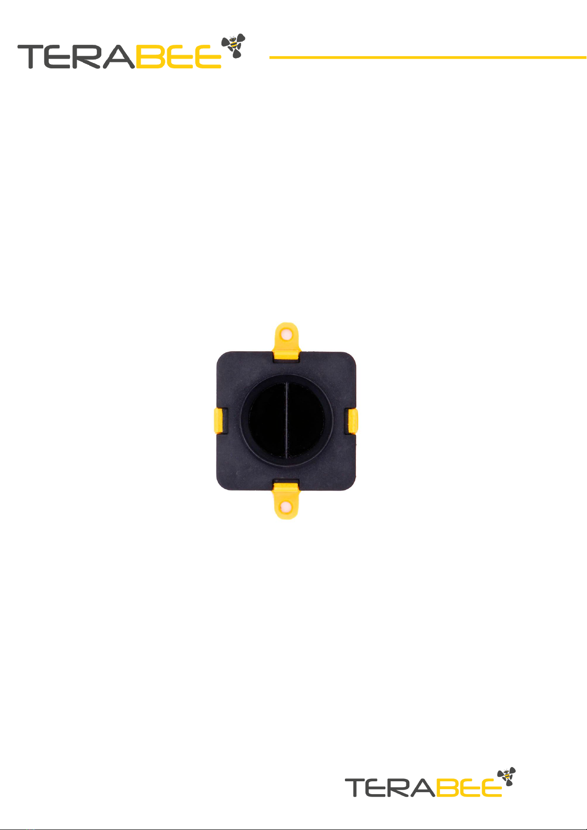
About the TeraRanger Evo Swipe Plus 4
Technical Specifications 5
Performance Table 6
Communication interfaces 6
Mechanical Integration 7
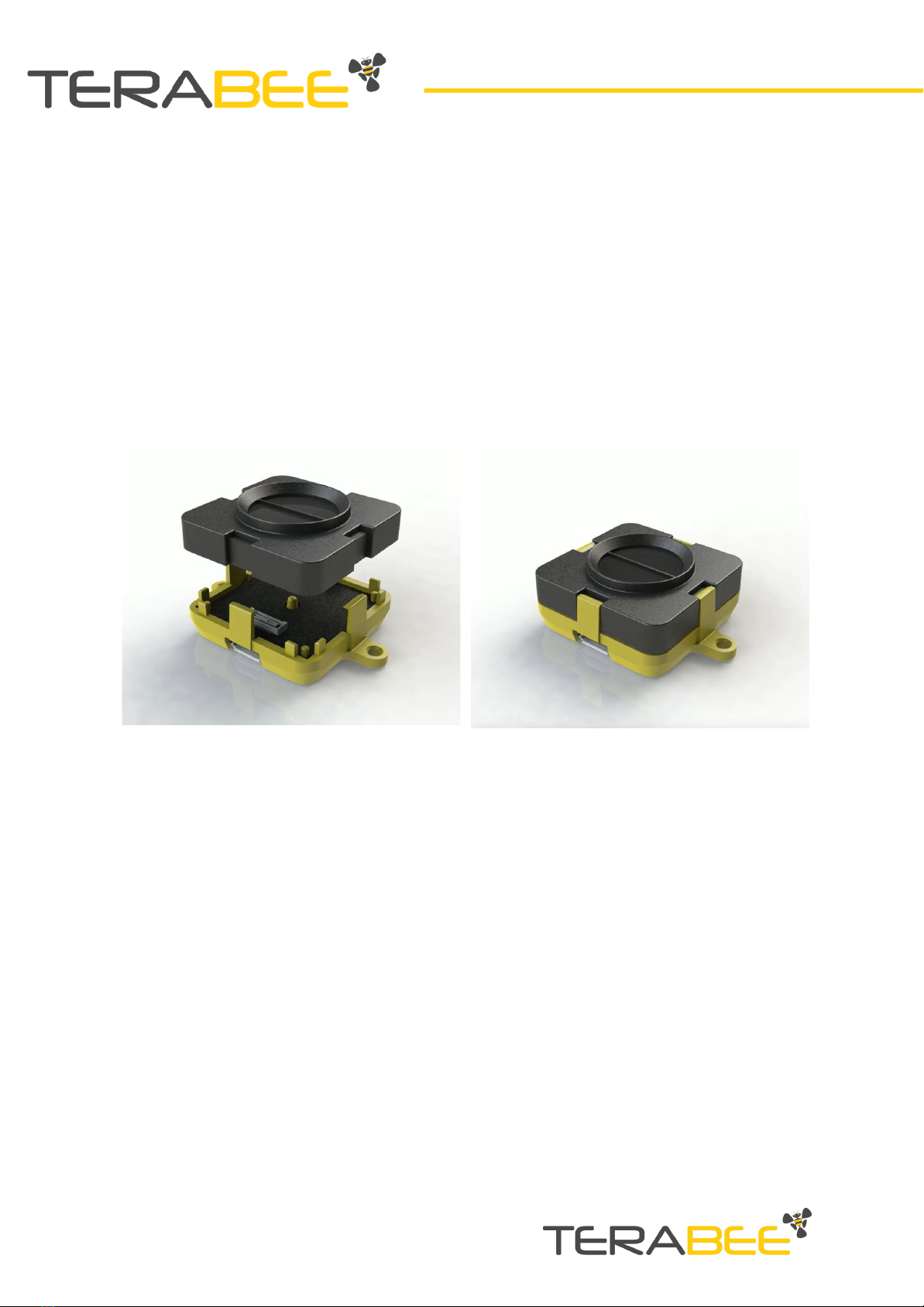
Modular design (clip-on, clip-off) 7
Mechanical design and mounting 7
Mounting solutions 9
USB Backboard Use 10
LED Indication 10
Normal operation 10
Error messages and troubleshooting 10
Connecting the TeraRanger Evo to a Host Computer 11
Windows OS 11
I2C/UART Backboard Use 14
I2C/UART pinout 14
LED Indicators 15
Normal operation 15
Troubleshooting 15
Electrical characteristics 16
USB/UART Normal Operation 16
Operating Modes of the TeraRanger Evo Swipe Plus sensor 16
Bidirectional People Traffic Detection Mode 16
Presence Detection Mode 17
Engagement Trigger Mode 17
Gesture Recognition Mode 18
Swipe Mode 18
Validation Mode 19
Installation of Graphical User Interface Package 19
Linux and Raspberry Pi 19
Windows 19
Graphical User Interface (GUI) 20
Bidirectional People Traffic Detection Mode 21
Presence Detection Mode 21
Copyright © Terabee 2020
Terabee, 90 Rue Henri Fabre
01630, St Genis-Pouilly, France (next to CERN)
2/29

Engagement Trigger Mode 22
Gesture Recognition Mode 22
Swipe Mode (Last gesture) 22
Validation Mode 22
Button to Reset Counters 22
List of sensor commands available via USB/UART 23
Details of the sensor output values 24
Output in Bidirectional People Traffic Detection Mode 24
Presence Detection Mode 25
Engagement Trigger Mode 25
Gesture Recognition Mode 26
General Remarks 29
Copyright © Terabee 2020
Terabee, 90 Rue Henri Fabre
01630, St Genis-Pouilly, France (next to CERN)
3/29

1. Introduction
Evo Swipe Plus provides four complimentary modes in one small sensor module that is
discreet and easy to integrate. The sensor will detect the presence of people and their
proximity to the sensor, it will understand which direction people are moving in and
switch to a touchless gesture recognition mode for people to interact with information
panels, kiosks and other devices. Its touchless gesture recognition features offer
convenience for users and companies by reducing the risk of virus transmission and the
need for constant disinfection of user interfaces.
1.1. About the TeraRanger Evo Swipe Plus
Figure 1. TeraRanger Evo Swipe Plus sensor, top view
The Evo Swipe Plus sensor has no open electronics and provides an ABS protected
enclosure, resulting in a dust-proof and robust operation.
Copyright © Terabee 2020
Terabee, 90 Rue Henri Fabre
01630, St Genis-Pouilly, France (next to CERN)
4/29

1.2. Technical Specifications
Table 1 - Technical specifications of TeraRanger Evo Swipe Plus
Product code
TR-EVO-SWP-PL-USB
TR-EVO-SWP-PL-UART
Performance
TeraRanger Evo Swipe Plus USB | UART
Detection Principle
Infrared Time-of-Flight
Light Source Wavelength
940 nm
Use Environment
Indoor
Field of View
27°
Operation Modes
Presence Detection (PD)
Bidirectional People Traffic Detection (BPTD)
Engagement Trigger (ET)
Gesture Recognition (GR)*
Electronics
Supply Voltage
5V DC +/-5%
Current Consumption Average
50 mA
Initialization Time
< 1 s
Communication
Serial Interface
USB 2.0 Micro-B
UART, +3.3V level, 115200,8,1, None
Visual Notification
3 x LEDs (built-in backboards)
Mechanical data
Dimensions
42 x 30 x 13 mm (incl. backboard)
Weight
9 g (incl. backboard)
Operating Temperature
-20° C to 75° C
Housing Material
ABS
Mounting Style
2 holes for M2 screws
Type of Connection
USB Backboard: USB 2.0 Micro-B
I2C/UART Backboard: DF13-7p connector
Copyright © Terabee 2020
Terabee, 90 Rue Henri Fabre
01630, St Genis-Pouilly, France (next to CERN)
5/29

Conformity
Reference Standard
CE, RoHS
*For optimal performance the users’ body should be more than 0.5 m from the sensor, with
their hand swiping in the 0.1 m to 0.5 m range of the sensor.
1.2.1. Performance Table
Table 2 - performance table of the evo swipe plus
Mode
Detection
Output
Bidirectional People
Traffic Detection
(BPTD)
~ 0.3 m to 1.7 m
~25 Hz
X: People inside
Y: People IN,
Z: People OUT
Presence Detection
(PD)
~ 0.2 m to 3 m
~20 Hz
String: “Presence” or “Person moved
away”
X : Presence count
Engagement Trigger
(ET)
~ 0.5 m to 1.5 m
PD~20 Hz
BPTD~25 Hz
Change Mode:
- BPTD or PD Modes to GR Mode
- GR Mode to BPTD or PD Modes
-String: “Engagement” or
“Disengagement”
Gesture Recognition
(GR)
Swipe:
~ 0.1 m to 0.5 m
~25 Hz
Validation:
~ 0.01 m to 0.15 m
~25 Hz
Swipe:
-String: “Left” or “Right”
Validation:
-String: “Validation”
1.2.2. Communication interfaces
Table 3 - Communication interfaces for the evo swipe plus
Evo Swipe Plus
Communication
Interfaces
USB
●
UART
●
Copyright © Terabee 2020
Terabee, 90 Rue Henri Fabre
01630, St Genis-Pouilly, France (next to CERN)
6/29

2. Mechanical Integration
2.1. Modular design (clip-on, clip-off)
The mechanical design of the main sensor module (black) allows easy assembly to its
backboard (yellow) using a simple ‘clip-on’ technique. When clipping the two together,
please ensure there is no visible gap between the black and yellow parts.
Figure 2 - Modular design of the TeraRanger Evo Swipe Plus sensor
2.2. Mechanical design and mounting
The TeraRanger Evo Swipe Plus sensor offers an ABS housing (both: sensor and
backboard), with an option to mount the sensor using two holes compatible with M2
screws. Figure 3 illustrates the external dimensions of the TeraRanger Evo Swipe Plus
sensor.
Copyright © Terabee 2020
Terabee, 90 Rue Henri Fabre
01630, St Genis-Pouilly, France (next to CERN)
7/29

Figure 3 - TeraRanger Evo Swipe Plus external dimensions, USB backboard
The USB Backboard includes two holes for mounting the sensor using standard M2
screws. The following methods can be used to mount the TeraRanger Evo Swipe Plus
sensor:
1- Front-panel mount using the M2 screws
2- Back-panel mount using the 2mm ledge on the front side of the sensor
Figure 4 illustrates the two different mount methods. The first solution allows for easy
surface attachment and rapid evaluation of the sensor. The second provides a more
discreet installation and supports design-in projects by installing the sensor behind a
surface (e.g panel), ideally with 2mm thickness.
Copyright © Terabee 2020
Terabee, 90 Rue Henri Fabre
01630, St Genis-Pouilly, France (next to CERN)
8/29

Figure 4 - Front-panel mounting (left image); back-panel mounting (right images)
2.3. Mounting solutions
When choosing a place for mounting the TeraRanger Evo Swipe Plus, please consider
the following recommendations:
●Mounting close to sources of heat or strong electromagnetic fields can decrease
sensor performance
●Do not mount anything directly in front of the sensor or in a cone of
approximately +/-35° around the central optical axis of the sensor
●It is advisable to avoid having other sources of Continuous Wave or modulated
Infrared light sources near the sensor
●Please consider that dust, dirt and condensation can affect sensor performance
●It is not advised to add an additional cover in front of the sensor
During assembly and integration, please observe all common ESD precautions. All
optical surfaces (sensor front) should be kept clean and free from contact with
chemicals.
Copyright © Terabee 2020
Terabee, 90 Rue Henri Fabre
01630, St Genis-Pouilly, France (next to CERN)
9/29

3. USB Backboard Use
3.1. LED Indication
3.1.1. Normal operation
Three LED indicators are present on the USB backboard, and are visible through the
back of the yellow plastic case.
Table 4 - LED indicators of the USB backboard
LED designator
Description
PWR (ORANGE)
The Power LED is ON whenever the sensor is powered
RED
Flashes briefly on startup to indicate proper initialization;
then switches off
GREEN
Blinks 8 times at power up
GREEN LED blinks every 5 seconds when the sensor is streaming
data
3.1.2. Error messages and troubleshooting
Table 5 - USB backboard LEDs troubleshooting
LED
designator
Sequence
Signification
Corrective actions
RED
Continuous
blinking
Sensor has detected a fault
and has stopped functioning
Check that the sensor is
properly connected to the
backboard, then restart
the sensor
RED /
GREEN
Both LEDs
blinking
continuously
Sensor has detected a fault in
the sensor initialization
process
Check USB output for
details of the error
Verify that the sensor is
properly connected and
re-power the unit
Copyright © Terabee 2020
Terabee, 90 Rue Henri Fabre
01630, St Genis-Pouilly, France (next to CERN)
10/29

3.2. Connecting the TeraRanger Evo to a Host Computer
3.2.1. Windows OS
In Windows it is possible to use any terminal emulation software for data display.
Terabee works with and suggests using HTerm software. Please follow the provided link
to download the software file (http://www.der-hammer.info/terminal/), and select the
appropriate file for your platform.
Tested with version 0.8.4 on Linux x64 and Windows 10 x64 platforms.
When using Windows, extract the downloaded zip file to the selected folder,
openitanddouble click on the “HTerm.exe” file.
When using Linux, extract the downloaded tgz file to the selected folder, make sure that
you have execution permission for the file “hterm” (command: chmod u+x hterm),
double click on the “hterm” file or run it from terminal while in its directory: ./hterm.
On Linux, consider removing the modemmanager package if you are sure that it is
not required by your system setup. This will shorten the initialization time of serial
devices in the Linux system:
sudo apt purge modemmanager
Connect the TeraRanger Evo Swipe Plus to a computer and select the corresponding
USB port (click “R” button to refresh the port list). Please configure the software with the
following parameters:
Baud rate : 115200 bit/s
Data bits : 8
Stop bit : 1
Parity bit : None
For easier data reading, select the “LF” option from the “Newline at” drop-down field.
See Figure 5 below for visual instructions.
Copyright © Terabee 2020
Terabee, 90 Rue Henri Fabre
01630, St Genis-Pouilly, France (next to CERN)
11/29

Click on LF, and in the line-end marker select the header of the operating mode for
easier data reading.
Figure 5 - HTerm parameters for TeraRanger Evo Swipe Plus
Once the USB port is selected and the parameters correctly set, click on the “Connect”
button.
The TeraRanger Evo Swipe Plus data will now appear in the “Received data” box
depending on the current working mode (see Figure 6).
Copyright © Terabee 2020
Terabee, 90 Rue Henri Fabre
01630, St Genis-Pouilly, France (next to CERN)
12/29

Figure 6 - Example of Data stream on HTerm software
Copyright © Terabee 2020
Terabee, 90 Rue Henri Fabre
01630, St Genis-Pouilly, France (next to CERN)
13/29

4. I2C/UART Backboard Use
The TeraRanger Evo Swipe Plus sensor can output data through a UART interface using
an I2C/UART backboard.
Figure 8 - I2C/UART backboard front view
4.1. I2C/UART pinout
The I2C/UART backboard uses a single 9 pin Hirose DF13 connector for interfacing to
the host system. The mating connector is a Hirose DF13-9S-1.25C with crimping contacts
DF13-2630SCF (tin) or DF13-2630SCFA (gold). Please consider the mechanical stability of
the mated connectors and avoid any kind of excess force on the connector (during
installation and once integrated) and follow the recommendations in the Hirose DF13
series datasheet (available here:
https://www.hirose.com/product/en/products/DF13) to ensure a reliable connection.
Table 6 - Pinout and description (According to DF13 datasheet)
Pin
Designator
Description
1
Tx
UART transmit output. 3.3V logic
2
Rx
UART receive input. 3.3V logic
3
GND
Power supply and interface ground
4
SDA
I2C serial data line. 3.3V logic
5
SCL
I2C serial clock line. 3.3V logic
6
rfu
RESERVED FOR FUTURE USE
7
5V
+5V supply input
8
GND
Power supply and interface ground
9
rfu
RESERVED FOR FUTURE USE
Copyright © Terabee 2020
Terabee, 90 Rue Henri Fabre
01630, St Genis-Pouilly, France (next to CERN)
14/29

4.2. LED Indicators
4.2.1. Normal operation
The I2C/UART Backboard has three built-in LEDs behind the yellow case to visualize
feedback of the sensor status. Table 7 lists the functionality of each LED of the I2C/UART
backboard.
Table 7 - LED indicators of the I2C/UART backboard
LED
Description
PWR (orange)
Power indicator, constantly ON when 5V is supplied
Rx (red)
Tx (green)
I2C/UART receive and transmit indicators.
Single blink for each data received or sent
4.2.2. Troubleshooting
Table 8 - I2C/UART backboard LEDs troubleshooting
LED
designator
Sequence
Signification
Corrective actions
RED
Continuous
blinking
Sensor has detected a fault
and has stopped functioning
Check that the sensor is
properly connected to
the backboard,
then restart the sensor
RED /
GREEN
Both LEDs
blinking
continuously
Sensor has detected a fault
in the sensor initialization
process
Check I2C/UART output
for details of the error
Verify that the sensor is
properly connected and
restart
Copyright © Terabee 2020
Terabee, 90 Rue Henri Fabre
01630, St Genis-Pouilly, France (next to CERN)
15/29

4.3. Electrical characteristics
Table 9 - TeraRanger Evo Swipe Plus power consumption
Parameter
Minimum
Maximum
Average
Power supply
Voltage input (V)
Current consumption (mA)
4.5V
25mA
5.5V
75mA
5V
50mA
Interface logic levels
(referenced to +3V3)
LOW
HIGH
-
2.3
1
-
-
-
5. USB/UART Normal Operation
5.1. Operating Modes of the TeraRanger Evo Swipe Plus
sensor
The TeraRanger Evo Swipe Plus features 4 modes:
●Bidirectional PeopleTraffic Detection Mode
●Presence Detection Mode
●Engagement Trigger Mode
●Gesture Recognition Mode (includes Swipe and Validation sub-modes)
5.1.1. Bidirectional People Traffic Detection Mode
In Bidirectional People Traffic Detection Mode, the sensor counts people passing in
front of the TeraRanger Evo Swipe Plus.
The output of the sensor is:
●A meter counting the number of people passing by, from left to right
●A meter counting the number of people passing by, from right to left
The sensor should be installed with the USB/UART Connector on the right side as shown
in figure 9.
Copyright © Terabee 2020
Terabee, 90 Rue Henri Fabre
01630, St Genis-Pouilly, France (next to CERN)
16/29

Figure 9: Sensor orientation for People Counting Mode
The detection range of this mode can be adjusted from a minimum of 0.3 m to a
maximum of 1.7 m. To detect a person passing the set detection range has to be
breached.
5.1.2. Presence Detection Mode
In Presence Detection Mode, the sensor counts people passing by in front of the Evo
Swipe Plus, regardless of their direction. A presence is detected when a person is
standing at a set range for a set time. The sensor registers that a person has left when
their distance from the sensor is equal to or above the maximum range for the specified
amount of time
The output of the sensor is:
●A character string reporting that a person enters or leaves the field of detection
of the sensor
●A meter counting the number of people detected
The time threshold of this detection mode can be adjusted from a minimum of 0,1
second to a maximum of 3 seconds.
The detection range of this mode can be adjusted from a minimum of 0.2 m to a
maximum of 3.0 m, the default range being 2.5 m.
Note: The “Bidirectional People Traffic Detection Mode” and “Presence Detection
Mode” are exclusive. Please refer to section 5.3 “Graphical User Interface (GUI)” to read
how to switch between the 2 modes.
5.1.3. Engagement Trigger Mode
In Engagement Trigger Mode, the sensor raises a flag when a person is identified as
engaged, meaning standing at a set range for a set time. When this situation occurs, the
Copyright © Terabee 2020
Terabee, 90 Rue Henri Fabre
01630, St Genis-Pouilly, France (next to CERN)
17/29

sensor switches from Presence Detection or Bidirectional People Traffic Detection Mode
to Gesture Recognition Mode - read details in the next section.
When the “engaged” person is leaving, the sensor detects the change and switches back
from Gesture Recognition Mode to Presence Detection Mode or Bidirectional People
Traffic Detection Mode.
When changing its state, the sensor outputs a character string corresponding to
Engagement or Disengagement.
The time threshold of the engagement trigger mode can be adjusted from a minimum
of 1 second to a maximum of 10 seconds. The time of disengagement can vary from 1
to 10 seconds.
By default, the set engagement range is 1 m, and can be adjusted from a minimum of
0.5 m to a maximum of 1.5 m.
5.1.4. Gesture Recognition Mode
Gesture Recognition Mode comprises 2 sub-modes operating at the same time: Swipe
Mode and Validation Mode.
5.1.4.1. Swipe Mode
Swipe Mode activates when a person is “engaged” - refer to above section 5.1.3
Engagement Trigger Mode.
Swipe Mode: the sensor detects Left to Right or Right to Left hand gestures performed
in front of the sensor. The connector of the USB/UART backboard should be placed on
the right, Figure 10 illustrates the correct orientation of the TeraRanger Evo Swipe Plus.
Figure 10: Sensor orientation for Swipe Mode
●When a person performs a Right to Left gesture, the sensors outputs a character
string “Left”
Copyright © Terabee 2020
Terabee, 90 Rue Henri Fabre
01630, St Genis-Pouilly, France (next to CERN)
18/29

●When a person performs a Left to Right gesture, the sensor outputs a character
string “Right”
The default working range is from 0.2 m to 0.4 m, and can be adjusted from a minimum
of 0.1 m to a maximum of 0.5 m.
The user’s body should be more than 0.5 m away from the sensor, with their hand swiping
in the 0.1 m to 0.5 m range of the sensor, to avoid negatively affecting the sensor’s
behavior and to remain out of the sensor’s field of view.
Notes:
1. A minimum of 0.1 m is required between minimum and maximum working
ranges
2. For an optimal use, a minimum of 0.25 m is required for the maximum working
range of Swipe Mode and the minimum working range of Engagement Trigger
Mode.
5.1.4.2. Validation Mode
Through validation mode, the sensor detects a validation event when a person places
his/her hand below a set distance in front of the sensor for a set duration (a few
seconds). When a validation is acknowledged, the sensor outputs a character string
“Validation”.
The default working range is 0.15 m, and can be adjusted from a 0.01 m to 0.15 m.
Note: For optimal use, a minimum of 0.05 m is required between the validation working
range and the minimum working range of Swipe Mode.
5.2. Installation of Graphical User Interface Package
5.2.1. Linux and Raspberry Pi
Instructions:
●Open a terminal in the evo_swipe_plus folder (evo_swipe_plus-arm for Raspberry
Pi and other Armv7l)
●Type: Pip install -r requirements.txt
●Launch: main.py by typing: python3 main.py
5.2.2. Windows
Instructions:
●Double click on EvoSwipePlus_1.2 to launch executable and Install.
Copyright © Terabee 2020
Terabee, 90 Rue Henri Fabre
01630, St Genis-Pouilly, France (next to CERN)
19/29

●To launch the GUI double click on the icon “EvoSwipePlus” on the Desktop
●To launch with terminal information, right click on the icon and choose “Open file
location”.
●Open a cmd terminal there and type the command: “cd ..” and then
Python\python.exe pkgs\main.py
5.3. Graphical User Interface (GUI)
The GUI allows you to:
● Set up the parameters for the different modes of Evo Swipe Plus sensor
●Bidirectional People Traffic Count
●Presence Count
●Engagement Trigger
●Swipe (Swipe: Last Gesture)
●Validation (Validation Status)
●Test in near real-time the behavior of Evo Swipe Plus sensor and report the
status and counts related to its different modes
Important:
Once you update the parameters through the GUI (e.g. Presence Detection Mode or
thresholds with the sliders), these parameters are automatically pushed to the
TeraRanger Evo Swipe Plus sensor
You can read the details of the GUI on Figure 11 below.
Copyright © Terabee 2020
Terabee, 90 Rue Henri Fabre
01630, St Genis-Pouilly, France (next to CERN)
20/29
Other manuals for TeraRanger Evo Swipe Plus
1
This manual suits for next models
2
Table of contents
Other TeraBee Recording Equipment manuals