AWT420 | UNIVERSAL 4-WIRE, DUAL-INPUT TRANSMITTER | INF/ANAINST/012-EN REV. A 7
4 Hazardous area considerations
Health & Safety
Safety precautions
Be sure to read, understand and follow the instructions
contained within this manual before and during use of the
WARNING
Serious damage to health/risk to life
The AWT420 transmitter is a certified product suitable for
use in hazardous area locations. Before using this product
refer to the product labeling for details of hazardous area
certification. Maintenance and installation must be carried
out only by the manufacturer, authorized agents or persons
conversant with the construction standards for hazardous
Potential safety hazards
WARNING
Bodily injury
following points must be observed:
• Up to 240 V AC may be present. Be sure to isolate the
supply before removing the terminal cover.
described in this manual or any relevant Material Safety
Company, together with servicing and spares information.
Safety standards
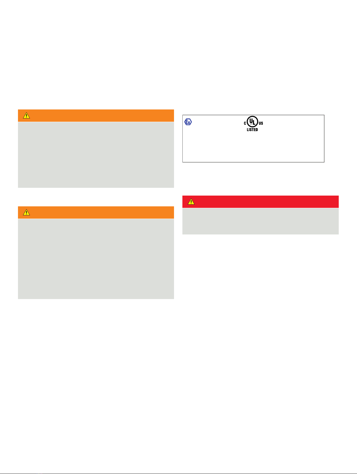
Name plate/Certification label
The following name plate is an example only. The name plate
attached to the transmitter may be different.
Transmitters with cULus approval and ATEX IECEx
(Aluminum Enclosure)
Figure 3 Example of hazardous area name plate
Service and repair
DANGER
The product has no live maintenance facility. The instrument
must be de-energized before any maintenance is
performed.
If the instrument is located in a hazardous area none of the
instrument’s components can be serviced by the user. Only
personnel from ABB, its approved representative(s) or persons
conversant with the construction standards for hazardous area
the system and only components formally approved by the
manufacturer should be used. Any attempt at repairing the
instrument in contravention of these principles could cause
damage to the instrument and corporal injury to the person
carrying out the repair. It renders the warranty null and void and
could compromise the hazardous area certification, correct
working of the instrument, electrical integrity and the CE
compliance of the instrument.
If you have any problems with installation, starting or using the
instrument please contact the company that sold it to you. If
this is not possible, or if the results of this approach are not
satisfactory, please contact the manufacturer’s Customer
Service.
E474414
WARNING – DO NOT OPEN IN AN AREA WHERE
AN EXPLOSIVE ATMOSPHERE MAY BE PRESENT
PROCESS CONTROL EQUIPMENT FOR
USE IN HAZARDOUS LOCATIONS
EZLink channels fitted,
Class I, Div 2, Gps A, B, C, D, T4 providing
non-incendive field wiring outputs for Class I
Div 2 Grps A, B, C, D Hazardous locations
No EZLink channels fitted,
Class I, Div 2, Gps A, B, C, D, T4
-10
C
≤ Ta ≤
+45
C
USA: Installation Drg 3KXA005001U0101
Canada: Installation Drg. 3KXA005001U0201
IECEx ULD 20.0009X
The equipment shall only be used in an
area of at least Pollution Degree 2,
as defined in IEC 60664-1
General Arrangement Drg.3KXA005002U0101
Installation Drg. 3KXA005001U0301
EZLink channels fitted,
II 3(3) G Ex ic ec nC [ic Gc] IIC T4 Gc,
No EZLink channels fitted,
II 3 G Ex ic ec nC IIC T4 Gc,
-10
C ≤ Ta ≤
+45
C, IP66,
DEMKO 20 ATEX 2259X
AVERTISSEMENT – NE PAS OUVRIR DANS UN EMPLACEMENT
OÙ UNE ATMOSPHÈRE EXPLOSIVE PEUT ÊTRE PRÉSENTE