Samsung SUT-80 User manual

ENGLISH
Thank you for choosing this Samsung UTP TRANSMITTER & RECEIVER product.
Before attempting to connect or operate this product, please read the instructions contained in this
manual carefully.
Please save this instruction manual for future reference.
UTP TRANSMITTER & RECEIVER SUT-80/SUR-10 USER’S MANUAL

UTP Transmitter & Receiver User's Manual
2
UTP Transmitter & Receiver User's Manual
3
Samsung Techwin cares for the environment at all product manufacturing
stages, and is taking measures to provide customers with more environmentally
friendly products.
The Eco mark represents Samsung Techwin’s devotion to creating
environmentally friendly products, and indicates that the product satisfies the EU
RoHS Directive.
Cautions/Warnings for Installation
Cautions/Warnings for Use
Table of Contents
1. Product Introduction ……………………………………………………… 4
1-1. Overview ……………………………………………………………… 4
1-2. Product Features ……………………………………………………… 4
2. Product Parts and Peripheral Device Connection…………………………… 5
2-1. Part Names and Functions …………………………………………… 5
2-1-1. SUT-80
2-1-2. SUR-10
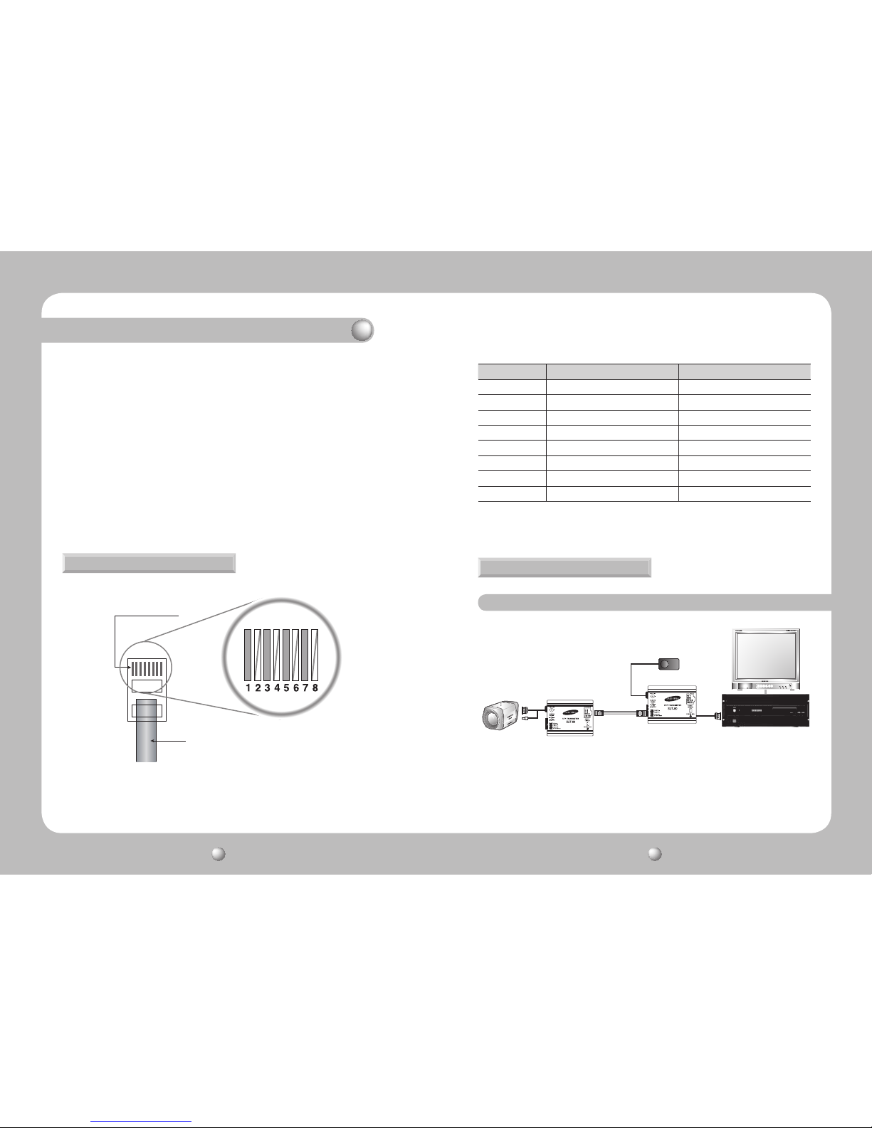
2-2. Connecting UTP Cable ………………………………………………… 6
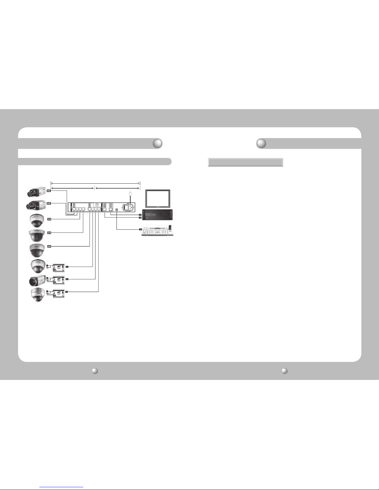
2-3. Peripheral Device Connection ………………………………………… 7
2-3-1. SUT-80, SUR-10 Configuration Example
2-3-2. SUT-80, SUJ-800 Configuration Example
3. Cautions/Warnings ………………………………………………………… 9
3-1. Cautions for Installation & Use ………………………………………… 9
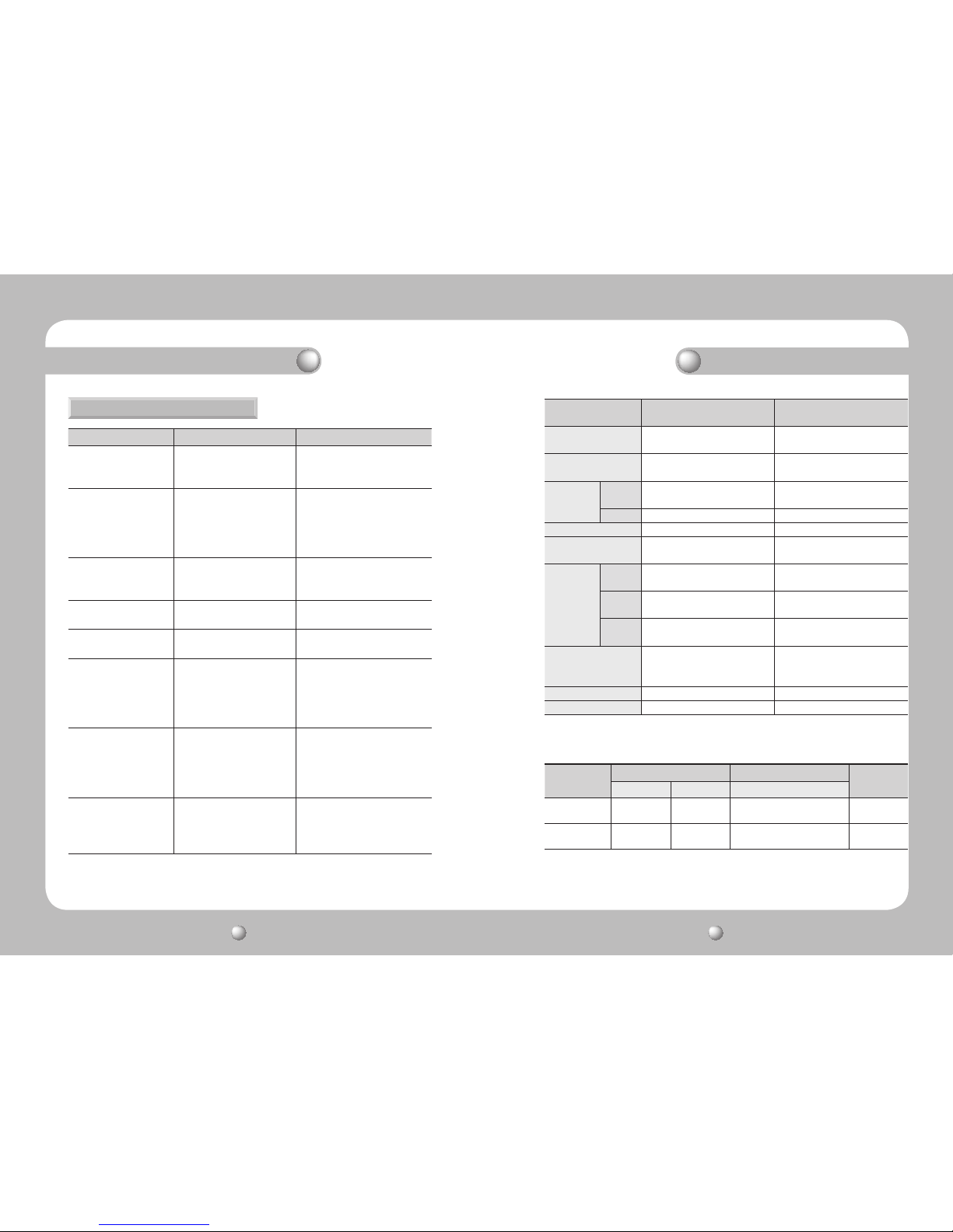
3-2. Troubleshooting ………………………………………………………… 10
4. Specifications ……………………………………………………………… 11
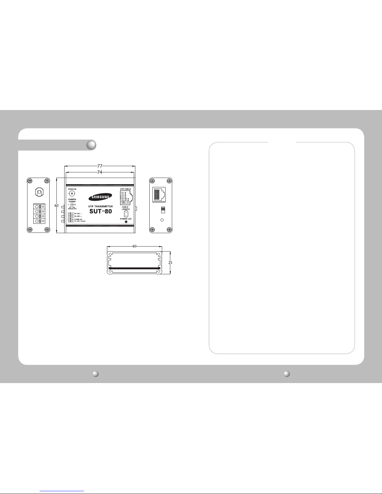
5. Dimension ………………………………………………………………… 11
Before installing this product, please read the following cautions and warnings carefully.
Do not install the product in the following locations.
■
Places under extremely high or low temperature conditions
- Use this product under temperature conditions only between -15℃and +40℃to
prevent low performance and product malfunctions.
■
Places exposed to rain, snow, or high humidity
- Avoid water and moisture leakage into the product; it may cause the product to
malfunction.
■
Places containing or exposed to oil and gas
- Oil, moisture, and gas leakage into the product may cause product malfunctions.
■
Places exposed to vibration and shock
- Vibration and shock may cause product malfunctions.
■
Places under direct sunlight or exposed to outdoor weather conditions
- Direct sunlight and severe weather conditions may cause product malfunctions.
■
Places exposed to radio waves (RF) or near power cables
- Radio communication devices and electromagnetic waves from power lines may
cause product malfunctions.
■
Do not disassemble the product or insert foreign objects.
- Disassembly of the product or insertion of foreign objects such as metal may cause
break or damage the unit.
■
Make sure to turn off the product prior to installation.
- Before installing your product, please check its voltage rating and then turn on the
power.
■
Do not subject the product to physical shock or exert excessive force to operate the product.
- Shocks and excessive force on the components such as circuits may break or
seriously damage the unit.

UTP Transmitter & Receiver User's Manual
4
UTP Transmitter & Receiver User's Manual
5
1. Product Introduction
1-1. Overview 2-1. Part Names and Functions
1-2. Product Features
The UTP Video Transmitter & Receiver (SUT-80, SUR-10) converts the imbalance differential
signals of CCTV cameras to balanced differential signals and transmit them via twisted pair
cable (UTP, FTP, STP), enabling long-distance signaling without the interference of differential
noise. Our UTP video transmitter & receivers are also capable of supplying power to
connected cameras and transmitting camera control data using an extra cable.
VIDEO IN :
Connect the video output terminal of a camera.
CAM POWER :
The power output terminal for a camera.
Do not connect a camera that uses a different power supply. (In case a
different power supply is used, please connect the enclosed load resistor.
)
RS-485 :
RS-485 data terminal. Caution: Polarity sensitive.
POWER IN :
Connect an extra adapter.
Do not use if the receiver and junction box are used for the supply power.
UTP CABLE :
Connect a UTP cable attached with an RJ-45 plug.
CABLE LENGTH :
Adjust the software according to the length of the UTP cable.
Max Distance Low (L): ~600m / (H): 600~2.4km
POWER LED :
A red light turns on when the SUT-10 is powered on.
POWER IN :
The adapter terminal.
· Provides differential signaling for video, power, and data transmission using 1 UTP cable
· Minimizes the interference of various transmission noises
· Provides BNC harness for the user’s convenience
· 2-level distance adjustment switch (Low: ~600m, High: 600~2.4km)
·
Max B/W via UTP cable: 2.4km, Max color: Differential video signaling up to 1.5Km when set to High)
· Provides AMP & F.EQ gain adjustments for optimal video quality
· Double duty power options: AC 24V 300mA & DC 12V 500mA (SUT-80: DC48V only)
· Convenient wiring options using RJ-45 Connector
·
Compatible with the older models of CVBS out cameras CVBS in DVRs, monitors, and dividers
· Compatible with most UTP cameras and DVRs
· Light, compact size perfectly fit into housings
· When used with the SUJ-800, supplies power to a connected camera within 1km
(Output current: DC 12V MAX 300mA; only DC-voltage cameras are compatible)
2. Product Parts and Peripheral Device Connection
2-1-1. SUT-80
2-1-2. SUR-10

UTP Transmitter & Receiver User's Manual
6
UTP Transmitter & Receiver User's Manual
7
RS-485 :
RS-485 data terminal. Caution. Polarity sensitive.
POWER LED :
A red light turns on when the SUR-10 is powered on.
UTP CABLE :
Connect a UTP cable attached with an RJ-45 plug.
AMP :
Enables adjusting video levels.
F.EQ :
Enables adjusting video details.
CABLE LENGTH :
Adjust the software according to the length of the UTP cable.
Max Distance Low (L): ~600m/ (H): 600~2.4km
VIDEO OUT :
Connect the video input terminal of a DVR, monitor, or divider.
2-2. Connecting UTP Cable
2-3. Peripheral Device Connection
2. Product Parts and Peripheral Device Connection
2-3-1. SUT-80, SUR-10 Configuration Example
No. Color Function
1 Orange VIDEO +
2 Orange + White VIDEO -
3 Green DATA +
4 Green + White DATA -
5 Blue POWER +
6 Blue + White POWER +
7 Brown POWER -
8 Brown + White POWER -
SUT-80
SUR-10 UTP DVR
Adaptor
Copper Connector
UTP Coating

UTP Transmitter & Receiver User's Manual
8
UTP Transmitter & Receiver User's Manual
9
3. Cautions/Warnings
3-1. Cautions for Installation & Use
●Make sure to turn the product off prior to installation.
●When installing the product, allow for smooth air circulation and avoid
extremely high temperatures and humidity as well as extremely low
temperatures.
●Keep this product away from magnetic objects.
●Some components in this product may create a risk of electric shock.
Please use extra caution for electric shock while using the product.
●Do not connect devices with voltage ratings higher than the product’s
standard voltage; there is a risk of fire and product malfunctions.
●The operating temperature of this product is between -15℃and 45℃.
Do not expose the product to higher or lower temperatures by installing
it in an outdoor location.
●While installing or using the product, do not subject the product to
extreme vibration or shock; it may cause product malfunctions.
●When installing the product, make sure to wire the product and
peripheral devices properly. Do not switch the lines.
●Before turning on the product, make sure that control cables connected
from all external devices are properly insulated.
[When Configured with the UTP Cameras and SUT-80]
500~1000m 500 ~ 1000m
RS-485 Data Line
SUT-80
SUT-80
SUT-80
SUJ-800
UTP Power Supply Unit
VIDEO MAX 1.8Km
CAMERA Power MAX 1Km
2. Product Parts and Peripheral Device Connection
2-3-2. SUT-80, SUJ-800 Configuration Example

UTP Transmitter & Receiver User's Manual
10
UTP Transmitter & Receiver User's Manual
11
3-2. Troubleshooting
Symptom Checkpoint Countermeasure
I can't turn on the
product.
Please make sure that the
adapter is turned on.
If the adapter is turned on and
the product does not operate,
replace the adapter.
The receiver is supplying
power to a camera
(Power LED on), but
the camera does not
operate.
Please make sure that the
Rx and Tx are within 1km of
each other.
If the distance between the Rx
and Tx is farther than 100m,
install an extra adapter on the Tx.
I want to connect a DC-
voltage camera.
Please check the input
current of the Rx: AC or DC.
Change the RX voltage to DC.
(Make sure to check the input
current.)
The video colors look
different on the monitor.
Please check the F.EQ gain
adjustment.
Adjust the color details using the
F.EQ adjustment option.
The video level looks
different on the monitor.
Please check the AMP
adjustment.
Adjust the video level using the
AMP adjustment option.
I can't transfer video
data from the camera.
Please check the UTP cable
terminal and pin alignment.
If the RJ-45 UTP cable is
connected improperly or the
cable pins are not aligned
properly, remove and reconnect
the RJ-45 modular jack.
485 connection error Please check the 485
communication cable.
Make sure that the 485
communication cable is
connected with the proper
polarity relationship and the
cable pins are aligned correctly.
Video looks distorted on
the monitor.
Please adjust the UTP cable
length according to the distance
between the Rx and Tx.
If the distance is farther than
600m, adjust the cable length
to High and to Low if it is shorter
than 600m.
3. Cautions/Warnings
4. Specifications
MODEL SUT-80 (1-Channel
Transmitter)
SUR-10 (1-Channel
Transmitter)
Video Input Signal CVBS 1.0Vp-p, 75Ω terminal Distance Adjustment: Low 51Ω
1Vp-p, High 51Ω 2.5Vp-p
Video Output Signal Distance Adjustment: Low 51Ω
1Vp-p, High 51Ω 2.5Vp-p CVBS 1.0Vp-p, 75Ω terminal
POWER INPUT DC 48V 200mA W/ Adapter: DC 12V 500mA /
AC 24V 300mA
OUTPUT DC 12V 300mA Loop Through
Bandwidth 550MHz 550MHz
Max Transmission
Distance (CAT 5)
2-level distance adjustment
switch
2-level distance adjustment
switch
Connection
Port
Video
Input DC-F & BNC Harness RJ-45
Video
Output RJ-45 BNC Harness(45Cm)
DATA DATA : 4P Terminal Block
(1~2: DATA/ 3~4: POWER)
DATA : 4P Terminal Block
(1~2: POWER/ 3~4: DATA)
Operating
Temperature/
Humidity
-15℃~ +40℃/ 0 ~ 80% -15℃~ 40℃/ 0 ~ 80%
Material/Weight Aluminum/122g Aluminum/120g
Dimensions 75(W) x 60(H) x 25(D)mm 75(W) x 60(H) x 25(D)mm
Type Video Camera Power Supply
Communication
Color B/W SUT-80
Max Transmission
Distance
1.5Km 2.4Km 1Km 1.2Km
Recommended
Distance
~1.2km 1.5km 800m ~1.2km
■Recommended Distance
●
These figures are recommended distances for normal operation; there may be some variance depending on the
operational environment of the product.

UTP Transmitter & Receiver User's Manual
12
UTP Transmitter & Receiver User's Manual
13
5. Dimension
MEMO

UTP Transmitter & Receiver User's Manual
14
UTP Transmitter & Receiver User's Manual
15
MEMOMEMO

VAN 09. 06
www.samsungtechwin.com
www.samsungcctv.com
•SAMSUNG TECHWIN CO., LTD.
145-3, Sangdaewon 1-dong, Jungwon-gu, Seongnam-si Gyeonggi-do, Korea, 462-703
TEL : +82-31-740-8151~8 FAX : +82-31-740-8145
•SAMSUNG TECHWIN EUROPE CO., LTD.
Samsung House, 1000 Hillswood Drive, Hillswood Business
Park Chertsey, Surrey, UNITED KINGDOM KT16 OPS
TEL : +44-1932-45-5300 FAX : +44-1932-45-5325
•SAMSUNG TECHWIN AMERICA Inc.
1480 Charles Willard St, Carson, CA 90746, UNITED STATES
Tol Free : +1-877-213-1222 FAX : +1-310-632-2195
www.samsungcctvusa.com
SALES NETWORK
This manual suits for next models
1
Table of contents
Other Samsung Transmitter manuals