TEREN DPTH User manual

DPTH High Accuracy Differential Pressure Transmitter-Operation Manual Edition: A/2
1
DPTH High Accuracy Differential Pressure Transmitter
Applications & Features
Apply high accuracy MEMS sensor and digital technology,
can measure positive, negative or differential pressure, and
air velocity or volume
It can measure system pressure of fan, blower, filter,
furnace draft and orifice plate and can apply to various
clean room, biological safety cabinet, clean bench, ducts
collection, medical or pharmaceutical machine, etc.
Excellent temperature compensation and electromagnetic
interference (EMI) ability, good for applications in complex
EMI environments of industrial systems or equipments
Multiple ranges, engineering units and outputs
High accuracy up to 0.5% and range as low as 25Pa
Function keys: zero reset, units select, response time set,
square root output set (air velocity or volume), K factor
calibrate and area parameter’s input, etc.
Field upgradable LCD display module with unit indication
Square root output: when applying along with pitot tubes or
other air velocity or volume sensor, can supply linear output
for air velocity or volume
Specifications
Medium: on-combustible, non-corrosive air, insensitive to
moisture, dust, condensation and oil
Working Temp.: -20~70°C
Medium Temp.:0~60°C
Temp. Compensation: 0~50°C
Storage Temp.:-20~70°C
Working Pressure: overload 10xFS(<=1kPa)/8xFS(>1kPa)
burst 20xFS(<=1kPa)/10xFS(>1kPa)
Accuracy: ±0.5%FS(±1.0%FS@25Pa range)
Long term stability: ±0.5%FS /Year
Thermal effect: <0.03%FS/°C (zero), <0.04%FS/°C (FS)
Response Time: 0.5~30s, can be set by keys
Process Connection: 5mm ID tubing
Display: 4 digits LCD, with unit indication, field upgradable
Output: 0~10V, 4~20mA (2 wires), RS485 selectable
Output Load: ≤500Ω (current), ≥2kΩ (voltage)
Power: Voltage: 16~28VAC/ 16~35VDC
Current: 18.5~35VDC(RL=500Ω), 8.5~35VDC(RL=0Ω)
Unit select: by keys
Zero set: easy to reset by keys
Air velocity/volume: square root output set (air velocity or
volume), K factor calibrate and area parameter’s input
Materials: fire retardant ABS+PC(UL94V-0)
Protection: IP65
Weight: 180g
Approval: CE, meet EN61326-1 for industrial equipment
Models
Model
DPTH
High accuracy DP
transmitter
Range
X
Range selection
Output
1
0-10V
2
4-20mA(2 wires)
8
RS485/Modbus
Display
0
N/A
1
LCD
Measuring Ranges
Code
UNIT & Range & Display Resolution
Pa
Pa
kPa
in w.c.
mm w.c.
mbar
0
0-25
25.00
0.025
0.100
2.500
0.250
1
0-60
60.00
0.060
0.250
6.000
0.600
2
0-125
125.0
0.125
0.500
12.00
1.250
3
0-250
250.0
0.250
1.000
25.00
2.500
4
0-500
500.0
0.500
2.000
50.00
5.000
5
0-1000
1000
1.000
4.000
100.0
10.00
6
0-2500
2500
2.500
10.00
250.0
25.00
7
0-5000
5000
5.000
20.00
500.0
50.00
8
0-10000
10000
10.000
40.00
1000.0
100.00
1. Set the 5 engineering units by button keys and the related LCD indicator will be on.
2. For zero center models, add “Z” at the end of the model. For example, DPTH1**Z, means the range
is -30-0-30Pa. Only ranges 0~6 have this selection.
DPTH High Accuracy Differential Pressure Transmitter-Operation Manual Edition: A/2
2
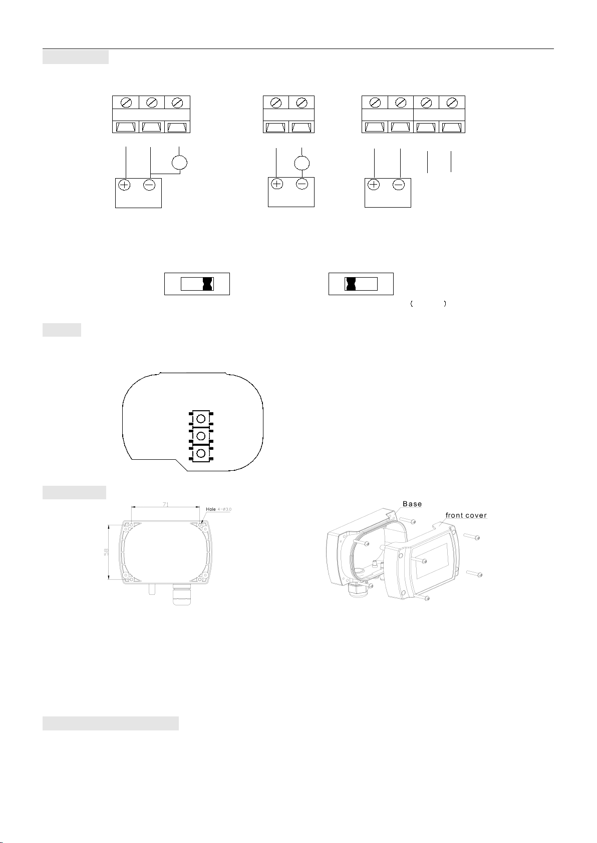
Connection
Different models have different electrical connections.
RS485/Modbus communication refer to “DPT series Modbus Communication Manual”. RS485 terminal resistance jumper J8 is
described as follows:
Terminal resistance 120 Ω:the jumper J8 is at position “on”
Terminal resistance 0 Ω(None):the jumper J8 is at position “off”
As shown below:
Button
“SET”: Set/Confirm/Save; “SEL”: Bit Select/Decrease/ Zero Reset(press for 5s); “ADJ”: Adjust/Increase;
See the operation instruction for the button operation.
SET
SEL
ADJ
Installation
● The installation site should be far away from heater, cooler, fan or other humidity and ventilation sources. Figure 1 is bottom
view of the product, for opening the 4 holes on the mounting surface.
● It should to be installed vertically on the wall, with the outlet gland downwards, shown as figure 2. Open the front cover and
screw the base on the mounting surface with 4 mounting screws.
● Feed the cable into the base through the cable gland, finish wiring according to the wiring diagram. Restore the front cover and
finish the pressure connection, pay attention to the difference between high (+) and low (-) pressure ports. Make sure to
completely air-tighten the gland to the base and the cover to the base with the seal rings, thus the housing overall protection
rate could meet up to IP65.
Zero reset & Calibration
According to different environment and sensor’s characteristics, for long term of using, the sensor’s accuracy maybe drift. The
transmitter should be zero reset after initial power on to meet the specified accuracy, and be zero reset periodically in every 6-12
months’ using. It is recommended to be “zero reset” after the initial 7 days continuous working.
Zero reset: keep the high(+)/low(-)pressure ports unconnected in stable air, or directly connect them, press the button “SEL”
for 5s to perform “zero reset”. It means “remove the zero drift of the transmitter in order to improve the accuracy”. It
isrecommended that this operation could be done periodically.
RS485
9600,8,N,1
Slave Add.= 1
BA
V
POWER SUPPLY
24VDC
A
POWER SUPPLY
24VDC/AC
V+ GND OUT
Voltage Output Model Current Output RS485 Model
POWER SUPPLY
24VDC/AC
V+ OUT V+ GND B A
120
J8
ON
1
120
J8
ON
1
Terminal resistance:120 Ω Terminal resistance:None Default
Figure 1
Figure 2

DPTH High Accuracy Differential Pressure Transmitter-Operation Manual Edition: A/2
3
Initial zero reset: when initial power on, it should be zero reset after fully warm-up and stable, to meet the specified accuracy.
Long term zero drift & reset: It may have long term zero drift after continuous working; customers can reset it periodically.
Re-calibration & zero reset: when re-calibration needed, zero reset should be done first. A qualified standard manometer is
needed for re-calibration operation. Please follow the operation procedures below.
Attention
It should be power OFF during installing and wiring. When using 24VAC, it is strongly recommended to power the unit with
independent transformer. If sharing a 24VAC transformer with other equipments such as controllers, transmitters or actuators,
please make sure the terminals 24V and GND are connected correctly. Otherwise, it may reduce serious damages.
Warranty
● It has limited warranty for eighteen (18) months after the production date.
● It does not extend to any unit that has been subjected to misuse or accident.
● It is, in any event, strictly limited to the replacement or repair of the product itself.
DPTH High Accuracy Differential Pressure Transmitter - Operation Instruction
(need LCD to apply)
Button definition:
“SET”: Set/Confirm/Save; “SEL”: Bit Select/Decrease/ Zero Reset(press for 5s); “ADJ”: Adjust/Increase;
Zero reset: keep the high(+)/low(-)pressure ports unconnected in stable air, or directly connect the two, press the button “SEL”
5s to reset the actual “zero point”. It means “remove the zero drift of the transmitter in order to improve the accuracy”. It is
recommended that this operation could be done periodically.
Operation instruction:
1."P810": Reset
SET→SEL/ADJ→P810→SET
User can restore the factory default set. Input “P810”, “Pret” will blink, press button SET, all factory default set will restore.
2. "P075": Set the response time (Default set: 0.5s, available range: 0.5-30.0s)
SET→SEL/ADJ→P075→SET→SEL/ADJ→XXX→SET. (XXX means set time).
3. "P083": Check LED display function, it will display the 4 digits one by one.
SET→SEL/ADJ→P083→SET
4."P081": Set Engineering Unit (Default set: 1, for engineering unit Pa, available ranges: 1-5)
SET→SEL/ADJ→P081→SET→SEL/ADJ→XXX→SET (XXX means the code of engineering unit),then the relevant LED on.
(Index: 1: Pa; 2: kPa; 3: mbar; 4: mmW.C.; 5: inW.C.)
5."P485": Set RS485 address(Default set: 1, available ranges 1~255, but recommend 1~32)
SET→SEL/ADJ→P485→SET→SEL/ADJ→XXX→SET (XXX means RS485 address)
Note:Refer to the communication data table
6."P483": Set RS485 Baud Rate (Default set: 9600, available 9600 or 4800)
SET→SEL/ADJ→P483→SET→SEL/ADJ→XXX→SET (XXX means Baud Rate index)
Index:1: 9600; 2: 4800.
7."P482": Set RS485 Parity Bit (Default set: 0, available 0,1 or 2)
SET→SEL/ADJ→P482→SET→SEL/ADJ→XXX→SET (XXX means Parity Bit index)
Index:0: none; 1: odd;2: Even.
System Error signal:
Err 1 Keys input operation code is wrong
Err 2 Input data is not available
Err 3 Modbusattempt to write read only register error
Err 4 Modbus CRC check error
Err 6 Password Key input error
Shenzhen TEREN Control Technology Co. Ltd.
Add: 3F, 2nd Industrial Zone, Nankeng, Longgang
District, Shenzhen,Guangdong,P.R.CHINA
Tel: 0755-23935155 Fax: 0755-23935156
web: www.teren.com.cn
TEREN website Alibaba shop
Table of contents
Other TEREN Transmitter manuals


