Termal HKED 261 X User manual
Technical Manual (07/2010 - VA1)
Monosplit “Wall” type Air Conditioners
“Personal Line DC Inverter” Models
Outdoor Units:
HCND 261 X
HCND 351 X
HCND 511 X
HCND 631 X
Indoor Units:
HKED 261 X
HKED 351 X
HKED 511 X
HKED 631 X

Monosplit “Wall” Personal Line DC Inverter - Table of Contents
- Table of Contents -
Table of Contents
1. GENERAL INFORMATION ........................................................................................................................... IG-1
1.1 GUIDELINES TO CONSULTATION & WARNINGS .......................................................................................IG-1
1.2 ESSENTIAL FEATURES OF THESE MODELS ..................................................................................................IG-2
1.3 APPEARANCE OF UNITS ............................................................................................................................IG-8
1.4 OUTLINE OF INDOOR & OUTDOOR UNITS ..............................................................................................IG-13
1.5 IR REMOTE CONTROL ..............................................................................................................................IG-14
1.6 LED PANEL ON INDOOR UNITS................................................................................................................IG-18
1.7 OPERATING USE CONDITIONS ................................................................................................................IG-20
1.8 HOW TO ADJUST AIR DIRECTION ............................................................................................................IG-21
1.9 EMERGENCY OPERATION & “SELF-CHECK” ..........................................................................................IG-23
1.10 AUTO-RESTART FUNCTON AFTER A BLACKOUT ...................................................................................IG-25
1.11 SUGGESTIONS FOR ECONOMIC USE OF SYSTEM ................................................................................IG-26
2. GENERAL TECHNICAL DATA .....................................................................................................................DG-1
2.1 SPECIFICATIONS .......................................................................................................................................DG-1
2.2 DIMENSIONS OF UNITS .............................................................................................................................DG-5
2.3 REFRIGERANT CIRCUIT DIAGRAMS .........................................................................................................DG-8
3. ELECTRICAL DATA .......................................................................................................................................DE-1
3.1 WIRING DIAGRAMS ..................................................................................................................................DE-1
3.2 R/T FEATURES OF TEMPERATURE SENSORS ..............................................................................................DE-5
4. CONTROL LOGIC FUNCTIONS ................................................................................................................... FU-1
4.1 HARDWARE FEATURES .............................................................................................................................. FU-1
4.2 SOFTWARE FEATURES ................................................................................................................................ FU-2
4.3 BASIC FUNCTIONS ................................................................................................................................... FU-13
4.4 SOME INDICATIONS OF MALFUNCTIONS & PROTECTION FUNCTIONS .............................................. FU-19
5. INSTALLATION ..............................................................................................................................................IN-1
5.1 CHECKS AND PRELIMINARY OPERATIONS ...............................................................................................IN-3
5.2 INSTALLATION OF INDOOR UNITS HKED 261, 351, 511, 631 X .................................................................IN-6
5.3 INSTALLATION OF OUTDOOR UNITS HCND 261, 351, 511, 631 X .......................................................... IN-21
5.4 VACUUM PROCEDURE AND REFRIGERANT CHARGE ..........................................................................IN-30
6. DIAGNOSTIC & MAINTENANCE ................................................................................................................DM-1
6.1 AUTODIAGNOSIS OF MALFUNCTIONS: ERROR CODES ON INDOOR UNIT ..........................................DM-2
6.2 FLOWCHARTS FOR MALFUNCTIONS’ SOLUTION ...................................................................................DM-7
6.3 CLEANING & MAINTENANCE OF AIR CONDITIONER .........................................................................DM-13

IG-1
Monosplit “Wall” Personal Line DC Inverter - Section 1: General Information
1. GENERAL INFORMATION
1.1 GUIDELINES TO CONSULTATION & WARNINGS
This Manual describes operation, installation and procedures for solving operation malfunctions of
HOKKAIDO Air Conditioners Monosplit “Wall” Personal Line DC Inverter HKED-HCND 261, 351, 511,
631 X”.
This Manual is addressed to Installers and to Authorized Technical Service, that is charged to interventions
for malfunction diagnosis and for repairing and/or servicing of system.
This Manual implies that Installers and Authorized Technical Service do know well the equipments and
tools which are usually used for repairing electric, mechanical parts and refrigerant components of
air-conditioning systems with R410A refrigerant. Furthermore, people who this Manual is addressed to
should know terms of current use that are used for describing relevant operations.
In particular, it is recommended to read and follow carefully Safety Precautions and Warnings that are listed
in this Manual. Missed observance of above prescriptions may lead to serious injuries to people, and even
to death.
Relevant Documents
This Manual is not exhaustive about system operation, so it has to be consulted together with the User
Manual, the Installation Sheets of Units and Spare Parts List referred to this Models of Units.
General Precautions and Warnings
WARNING
In order to avoid the risk of death or of serious personal injuries caused by electric shocks, disconnect the
power cable of Units before whatever intervention of repairing or maintenance.
WARNING
In order to avoid the risk of death or of serious personal injuries caused by electric shocks, NEVER tamper
with the ground wire for any reason. The appliance must always been equipped with a ground wire. Do not
remove the Safety label referred to ground wire, which is on the power cable. If the electric system on
installation site is not equipped of ground wire, please contact a qualified Electrician, for conforming electric
system to current Regulations.
WARNING
In order to avoid the risk of death or of serious personal injuries caused by overheating of the system’s
components, it is recommended to always make the system checked for verifying if there are malfunctions
or if the system often stops suddenly.
WARNING
In order to avoid the risk of death or of serious personal injuries caused by electric shocks, earth cables and
cables whose sheath colour corresponds to ground wires, must not be used for power lines of Phase and
Neutral. Standard colour of Ground wires is Green or Yellow/Green. The electric components such as
compressor and fan motors are provided of an individual Ground wire, connected to a metal part of the
appliance. When interventions of repairing or maintenance are carried out, the above Ground wires must
not be disconnected, unless dismantling and replacing of components are needed. Before ending whatever
intervention of repairing or maintenance, it is extremely important to connect again all Ground wires
eventually disconnected before.

IG-2
Monosplit “Wall” Personal Line DC Inverter - Section 1: General Information
1.2 ESSENTIAL FEATURES OF THESE MODELS
â Power modulation by DC Inverter control
Power supplied by system changes according to thermal load in installation environment. When
temperature inside the room reaches a value which is close to value set by User, compressor rotation
lowers, so as to allow a sensible reduction in power consumption. Moreover, as regards to traditional
thermostatic control systems (On-Off), compressor’s stops and restarts are less frequent - thus
permitting a reduction in power consumption and allowing an immediate increase in comfort.
â Energy high efciency (Class A/A)
All capacities (261, 351, 511, 631) of these systems meet requirements of Class “A” Energy Efciency,
both for operation in Cooling mode and for operation in Heating mode.
â “Ozone friendly” R410A refrigerant
R410A refrigerant does not damage ozone at all (ODP=0). Best performances assured by R410A
refrigerant allow a sensible reduction in refrigerant amount, which is required for the operation of
system. Both factors reduce the environmental impact of system.
â Advanced control for malfunction diagnosis
In case of eventual operation malfunctions, the most common among them will be shown by “Error
Codes” (“F_”) on LED Display of Indoor Unit and by the status of “Running” LED and “Timer”
LED placed on Indoor Unit’s frontal panel.
This allows targeted and therefore quicklier interventions for solving of eventual malfunctions.
â Operation control by infrared remote control (IR)
On IR remote control, there is a wide range of options, that is:
The possibility to program Timer operation (“Timer On”, or “Timer Off”) of system, within max.
24 hours, by steps of ±1 hour.
By “SLEEP” function, noise level of Indoor Unit can be reduced, as well as power consumption.
This operation option, that foresees rotation of Indoor Unit’s fan at Low speed and gradual “correction”
of temperature set by remote control, is available both in Cooling mode and in Heating mode.
“TURBO” function allows to reach desired temperature value quickier, as indoor fan speed is
set to max. available speed (“Ultra-HIGH”), for increasing the volume of air treated by Indoor Unit.

IG-3
Monosplit “Wall” Personal Line DC Inverter - Section 1: General Information
This operation option - which however is detrimental to noise level produced by Indoor Unit - is
available both in Cooling mode and in Heating mode.
“SWING” option: automatic swinging downwards and upwards of air outlet horizontal louver,
for a uniform distribution of air supplied in the room by Indoor Unit.
“Natural ow” option: sequence which consists in the upwards and downwards swinging of the
air outlet horizontal louver, for twice, followed by a 30-seconds’ stop of the louver and so on. This
is for simulating a light air current in the room.
“AIR FLOW” option: automatic swinging rightwards and leftwards of air outlet vertical louvers,
for a uniform distribution of air supplied in the room by Indoor Unit (this function is available on
HKED 511 X and HKED 631 X Models only).
â Automatic restart of Units after a power failure
Normally, after 3 minutes since power is restored, the system is able to restart with the settings
that were selected before the blackout. This means there is no need to press the “ON/OFF” button.
However, if “TIMER” operation had been previously selected, it will be cancelled and need to
be set again.
“SLEEP” function (see above), has to be expressly selected again as well.
“TURBO” function (see above), has to be expressly selected again as well.
In the same way, if “SWING” and/or “AIR FLOW” options (see above) were active when the
blackout occurred, they will be expressly selected again.
â Devices for a higher salubrity of air
HKED 261, 351, 511, 631 X Indoor Units are equipped of lters of mechanical type (net lters) at high
efciency air inlet, which can be easily reached for periodical cleaning.
â Advanced control of rotation of Indoor Unit’s fan
During starting in Heating mode, indoor fan will start rotating only after Indoor Unit’s heat exchanger
has reached a temperature which avoids cold air supply by Indoor Unit. This “preheating” may require
a time interval variable from 2 minutes to 5 minutes.
During thermostatic pauses in Heating mode, indoor fan speed will be reduced to the lowest
speed to avoid cold air supply by Indoor Unit.
At the end of operation in Cooling mode, indoor fan will keep on rotating for a certain time interval
since compressor’s stop, so as to allow the removal of the humidity left over on Indoor Unit’s heat

IG-4
Monosplit “Wall” Personal Line DC Inverter - Section 1: General Information
exchanger. This logic of operation is in order to prevent humidity stagnation and the consequent
forming of mould on Indoor Uni’s heat exchanger.
â Operation in Heating mode with very low temperature
These systems are able to operate in Heating mode also if outdoor temperature is very low: in
fact, the lowest value of operating range in Heating mode is - 15°C. However, in these extreme
conditions, as a consequence of the operation principle of “heat pump” systems, the performance
of system will result remarkably reduced as regards environmental normal use conditions of the
system itself.
â Appearance and functions: Indoor Units HKED 261, 351, 511, 631 X
Operation in Emergency mode: also if the IR remote control is temporarily unavailable or
malfunctioning, in any case it will be possible to start the system in “Auto Mode”. To that end, it
will be necessary to press the special button placed below the up-and-over frontal panel of Indoor
Unit. Therefore, the control electronics will automatically select the operation mode, on the basis of
temperature conditions inside the room.
These Indoor Units have a new design, so as to t harmoniously in residential environments.
Moreover, for each capacity of Indoor Unit it is available on demand a range that includes 4 frontal
decorative boards in different colours (available colours: “Black”, “Gold”, “Silver”, “Light-Blue”), in
addition to the white decorative board preinstalled in factory. The installation of one of frontal decorative
board allows to adapt Indoor Unit’s appearance to different residential environments. This operation
must be carried out only by qualied Personnel.
On these Indoor Units there is a LED Display, of orange colour, with 2 alphanumeric characters,
that is able to display alternatively the following information: set temperature value (°C), remaining
time (hours) of operation programmed by “Timer” function, starting up of automatic defrosting function
or an eventual “Error/Protection Code” in case of a malfunction of the system. As a consequence of
this, it is always possible to carry out an instant monitoring of the system’s operation status.
LED Display, which is usually off during system operation, may be lighted up according to User’s
needs by pressing “LAMP” button on IR remote control. For turning off LED Display, it is necessary
to press “LAMP” button again on IR remote control. By turning off LED Display, sources of light inside
the room can be reduced, thus making night rest more comfortable.
â Appearance and functions: Outdoor Units HCND 261, 351, 511, 631 X
Frontal grille and back grille are both treated against corrosion, and the same is true for bolts

IG-5
Monosplit “Wall” Personal Line DC Inverter - Section 1: General Information
and xation screws placed outside the chassis.
The refrigerant ttings (service valves) and the electrical connections (terminal blocks) are protected
from atmospheric agents (inltrations of rainwater) by panels and service covers.
IG-6
Monosplit “Wall” Personal Line DC Inverter - Section 1: General Information
Recapitulatory outline of main available functions on Units
Wide range of Error/Protection Codes that can be shown
on bright Display of Indoor Unit. “Self-Check” programme.
Indoor Units
ON/OFF by IR remote control
Indoor temperature sensor and outdoor temperature sensor.
Indoor heat exchanger temperature sensor and outdoor heat exchanger sensor.
Monitoring of temperature values
Room temperature is kept on the basis of temperature value set by remote control, by thermostat under microcomputer
control and compressor operation at variable speed (control by DC Inverter).
Ambient temperature control
During starting phase in Heating mode, indoor fan will rotate at set speed after a delay of a few seconds.
Anti-cold drafts prevention function
Between each ON/OFF cycle of system and the following one, at least 3 minutes must elapse.
Protection against close ON/OFF
“ULTRA-HIGH” speed, “HIGH” speed, “MED” speed, “LOW” speed, “BREEZE” speed.
Speed ranges of indoor fan
“Running” (Operation indicator), “Timer” (Indicator of starting up of Timer function, and corresponding remaining
time), “dF” (Defrosting), “F_” (Error Code) and “P_” (Protection Intervention): Indications on LED Display with 2 digits).
Logic control of horizontal air outlet flap
“Sleep”: Control of indoor fan and of set temperature for reducing noise level and electric power consumption.
“Turbo”: “ULTRA-HIGH” speed of indoor fan and max. frequency of compressor rotation, for reaching desired comfort quickier.
“Sleep” function and “Turbo” function
In environments with high humidity, this function allows to
restore quicklier your desired comfort conditions.
“DRY” function
Indications by Display + LED on frontal panel
Operation in Auto Mode
Simplified connections
Automatic defrosting
“TIMER On/Off” function
For preventing cold air supply during
starting in Heating mode.
“HOT- KEEP” function
Auto-Restart after a blackout
Autodiagnosis of malfunctions function
During starting phase, operation mode is automatically
selected according to indoor temperature conditions.
If you press “SWING” button on remote control to select “natural flow” mode, the horizontal air outlet flap on Indoor Unit
is controlled so as to simulate a light natural air inside the room.
Besides fixed stop positions, the automatic swinging of
air outlet flaps is also available.
Stop/swinging of air outlet flaps

IG-7
Monosplit “Wall” Personal Line DC Inverter - Section 1: General Information
Min. interval between ON/OFF cycles of compressor is of 3 minutes.
Outdoor Units
Timed ON/OFF of compressor
This kind of control allows a continuous modulation of system operation on the basis of thermal load and of desired comfort,
and allows to reduce power consumption especially at medium-low speed.
Control of compressor rotation speed by DC Inverter technology
For reducing noise level of outdoor fan, the shape of fan wheel has been expressly redrawn.
Outdoor fan with “silent” shape
Aluminium fins of outdoor heat exchanger ensure a higher efficiency in heat exchange.
Special fins in treated aluminium
It absorbs energy during operation in Heating mode only.
Protection against compressor’s overload
Anticorrosive surface treatment of chassis
Protection covers for electrical & refrigerant connections
Operation in Heating mode up to -15°C outdoor temperature
4-ways valve “energy saving” control
IG-8
Monosplit “Wall” Personal Line DC Inverter - Section 1: General Information
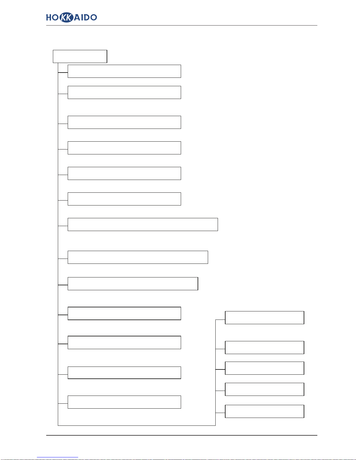
1.3 APPEARANCE OF UNITS
Indoor Units “Wall” Personal Line DC Inverter:
Models HKED 261 X, HKED 351 X
Frontal board standard “White” (by factory)
Models HKED 261 X, HKED 351 X
Frontal board optional “Black” (HSD-2-BCK)
Models HKED 261 X, HKED 351 X
Frontal board optional “Gold” (HSD-2-GLD)

IG-9
Monosplit “Wall” Personal Line DC Inverter - Section 1: General Information
Indoor Units “Wall” Personal Line DC Inverter:
Models HKED 261 X, HKED 351 X
Frontal board optional “Silver” (HSD-2-SLV)
Models HKED 261 X, HKED 351 X
Frontal board optional “Light-Blue” (HSD-2-LBL)

IG-10
Monosplit “Wall” Personal Line DC Inverter - Section 1: General Information
Indoor Units “Wall” Personal Line DC Inverter:
Models HKED 511 X, HKED 631 X
Frontal board standard “White” (by factory)
Models HKED 511 X, HKED 631 X
Frontal board optional “Black” (HSD-3-BCK)
Models HKED 511 X, HKED 631 X
Frontal board optional “Gold” (HSD-3-GLD)

IG-11
Monosplit “Wall” Personal Line DC Inverter - Section 1: General Information
Indoor Units “Wall” Personal Line DC Inverter:
Models HKED 511 X, HKED 631 X
Frontal board optional “Silver” (HSD-3-SLV)
Models HKED 511 X, HKED 631 X
Frontal board optional “Light-Blue” (HSD-3-LBL)
IG-12
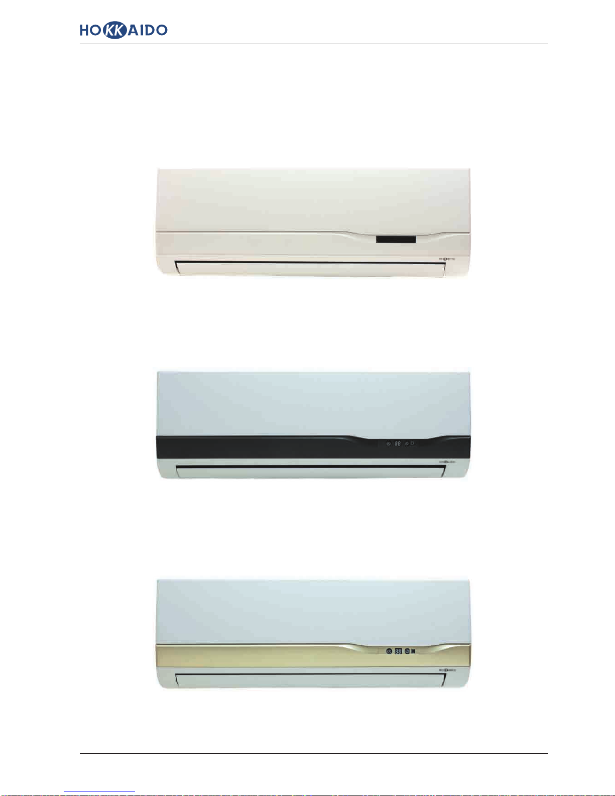
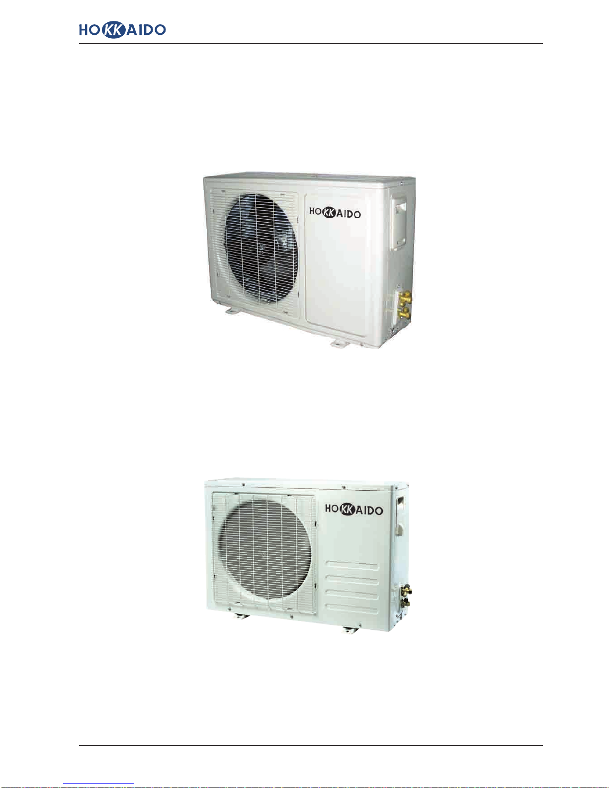
Monosplit “Wall” Personal Line DC Inverter - Section 1: General Information
Outdoor Units Personal Line DC Inverter:
Models HCND 511 X, HCND 631 X
Models HCND 261 X, HCND 351 X

IG-13
Monosplit “Wall” Personal Line DC Inverter - Section 1: General Information
Indoor Unit
Air inlet
Louver for adjusting air in
horizontal direction. The louver
is motorized on HKED 511, 631X
Models only.
Flap for adjusting air in
vertical direction.
Display Panel & LED Indicators
High efficiency air filter
Air inlet Electrical & refrigerant connections
Emergency button
a) Panel’s opening
Frontal panel of Indoor Unit
It removes impurities on air inlet.
Drain tube
Outlet air
Outdoor Unit
Air outlet
b) Panel’s closing
Press both sides of panel and pull the panel
towards you till max. opening angle (about 60°
as regards vertical position).
Never force the panel more than max. opening
angle.
Below the panel there is the Emergency Button,
which allows operation (in Auto Mode) if IR remote
control is not available.
Push the panel downwards till closing position,
indicated by the “click” of blockage mechanism.
Frontal panel
1.4 OUTLINE OF INDOOR & OUTDOOR UNITS
Note:
The Figures sideways are for explicative aim
only. The real appearance of components of
Units may be different from what is shown in
Figures.

IG-14
Monosplit “Wall” Personal Line DC Inverter - Section 1: General Information
1.5 IR REMOTE CONTROL
nIR Remote Control for Models HKED (261, 351, 511, 631) X
Notes:
¦For a detailed explication concerning the function of each button of IR remote control, and concerning
symbols which are shown on remote control’s LCD Display, please refer to the “User Manual” provided with
Indoor Units, or to the following pages.
¦For a detailed explication about options and operation modes of system, please refer to the “User Manual”
provided with Indoor Units.
¦Concerning these Models HKED-HCND (261, 351, 531) G (On-Off), even if “TURBO” button and “LAMP”
button are available on remote control, they refer to unavailable functions. Consequently, if you press these
buttons, there will be no effect on these systems.

IG-15
Monosplit “Wall” Personal Line DC Inverter - Section 1: General Information
n Outline of IR remote control’s buttons
Set Temperature “ON/OFF” Button
“SWING” Button
“AIR FLOW” Button
“SLEEP” Button
“LAMP” Button
“HOLD” Button
Operation Mode
Fan Speed
“Turbo” Button
“Timer” Button
Reception of signals trasmitted to Indoor Unit
To start/stop the system.
To select operation in “SLEEP” mode.
To change fan speed:
• LOW:
• MED:
• HIGH:
• AUTO:
(flashing).
MODE
FAN SPEED
TURBO
SWING
TIMER
HOLD
AIR FLOW
SLEEP
LAMP
These buttons allow to adjust
ambient temperature.
If you press “+” button, set
temperature is increased by 1°C.
If you press “-” button, set
temperature is reduced by 1°C.
The range of temperatures that
can be set is the following: 16°C ~
32°C.
(In “AUTO” mode and in “DRY”
mode, temp. is automatically set to
25°C and cannot be modified by
the User).
To select operation mode:
• “AUTO”
• “COOL”
• “DRY”
• “HEAT”
• “FAN”.
In COOL and HEAT modes, if you
press this button, operation in
“Turbo” mode is started up.
This function is not available on
these Models On-Off.
To programme the automatic start
(TIMER ON) or the automatic stop
(TIMER OFF) of system.
To select position of motorized
louvers for air outlet in horizontal
direction (left/right).
Flaps may swing continuously, or
stop in fixed position.
This function is available on
HKED 511 X, HKED 631 X Models
only.
To light up/go out the Display on
the Indoor Unit.
This button is not operating on
these Models.
To lock/unlock all buttons of remote
control.
If buttons of remote control are pressed by orienting correctly remote
control itself towards the IR receiver on Indoor Unit, signals will be transmitted
to Indoor Unit.
If signals have been correctly received, the buzzer on Unit emits a sound.
+
-
• “natural flow”: (ON).
• Swinging: (flashing).
• Fixed position : (ON).
To adjust motorized flap for air
outlet in vertical direction
(up/down):
In “DRY” mode, the flap’s angle is
adjusted in fixed position.
IG-16
Monosplit “Wall” Personal Line DC Inverter - Section 1: General Information
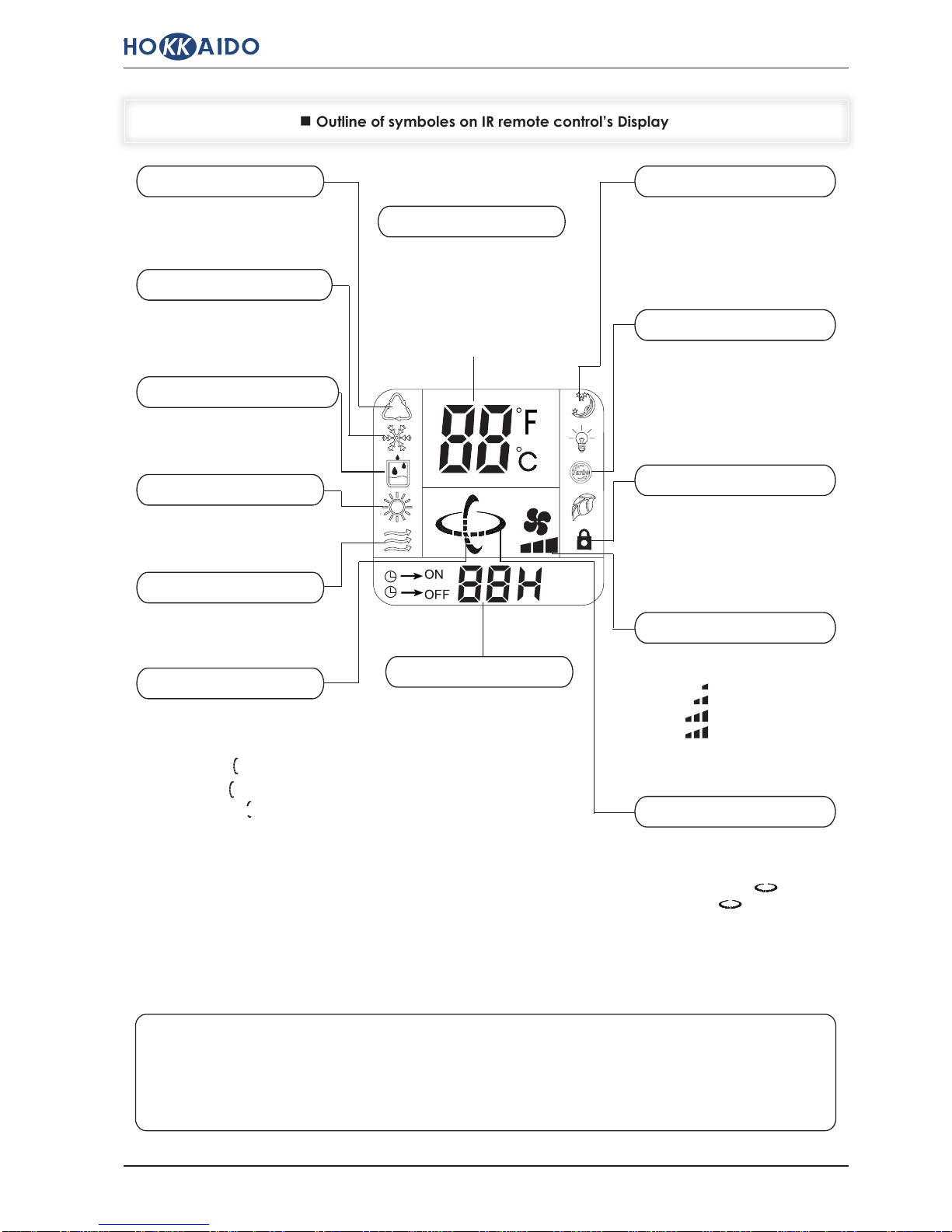
n Outline of symboles on IR remote control’s Display
TEMPERATURE
This indicator shows set temperature.
Range of temperature that can be
set is the following: 16°C ~ 32°C.
(In AUTO and DRY modes,
temperature is automatically set to
25°C and it cannot be adjusted by
the User).
Automatic Mode
Cooling Mode
Drying Mode
Heating Mode
Fan only Mode
“SWING” Indicator TIMER
It indicates TIMER setting.
“SLEEP” Indicator
“TURBO” Indicator
“KEY LOCK” Indicator
“FAN SPEED” Indicator
“AIR FLOW” Indicator
Notes:
The Figure above shows all possible indications that can be displayed on IR remote control’s
Display.
In reality, only indications referred to current operation selections will be displayed.
This symbol indicates that “AUTO”
Mode has been selected.
This symbol indicates that “COOL”
Mode has been selected.
This symbol indicates that “DRY”
Mode has been selected.
This symbol indicates that “HEAT”
Mode has been selected.
This symbol indicates that “FAN”
Mode has been selected.
It indicates that “SLEEP” mode has
been selected.
In COOL and HEAT modes, this
indicator lights up if “TURBO”
mode has been selected.
This function is not available on
these Models On-Off.
This indicator is displayed if remote
control’s buttons have been locked.
It indicates current setting of fan
speed:
• LOW:
• MED:
• HIGH:
• AUTO:
(flashing).
It indicates current setting of
motorized louvers for horizontal
adjustment (right/left) of air outlet:
• Automatic swinging: (flashing).
• Fixed angle: .
This function is available on
HKED 511 X, HKED 631 X
Models only.
• “natural flow”: (ON).
• Swinging: (flashing).
• Fixed position: (ON).
It indicates the setting of motorized
flap for air outlet in vertical direction
(up/down):
In “DRY” mode, the angle of flap is
adjusted in fixed position by control
electronics.

IG-17
Monosplit “Wall” Personal Line DC Inverter - Section 1: General Information
Make sure that batteries (“AAA” type, 1.5V) are fully charged and correctly tted in the special case
on remote control, by respecting the polarity marked on remote control itself. The average life of
batteries is of about 1 year. Never use rechargeable batteries.
Use the remote control by turning it towards the Indoor Unit at no more than 8 metres from the Unit’s
IR receiver.
Remote control will not work properly if curtains, doors or other objects placed between remote
control and Indoor Unit’s IR receiver do not allow the transmission of signals sent to Indoor Unit. In
these cases, the operating range of remote control will be remarkably reduced.
If remote control is placed sideways as regards the signal receiver, remote control will operate within
a maximum angle of 30° on the right or on the left of receiver. If remote control is xed on its wall
bearing, it will work within a side max. distance of 0.5 metres on the right or on the left of receiver.
If IR receiver on Indoor Unit is exposed to direct sunlight, remote control (and consequently the air
conditioner) may not work properly.
In order to avoid interferences, keep remote control at least 1 metre away from Hi-Fi, TV, etc.
If remote control does not work properly, press “RST” button (reset of settings) placed on the back
of the remote control itself. Check if remote control do operate properly now. Otherwise, remove
both batteries from remote control, then wait for a few minutes and reinstall batteries in their case.
Never wet the remote control and prevent any liquid from falling on it.
Do not use any liquid, solvent or detergent for cleaning the remote control. Use only a soft cloth,
clean and dry.
Maximum allowed distance: 8 metres
n Recommendations for the correct use of IR remote control
IR receiver for remote
control
IG-18
Monosplit “Wall” Personal Line DC Inverter - Section 1: General Information
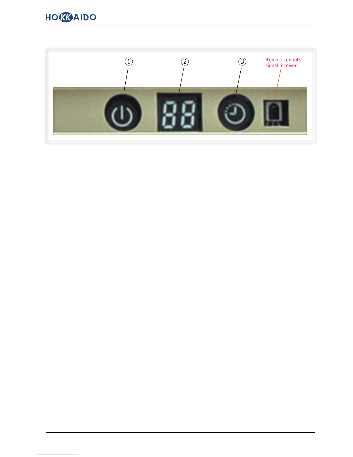
Remote control’s
signal receiver
1
“Running” LED (Orange):
It lights up when the Indoor Unit is operating.
It goes out when the Indoor Unit is OFF (stop by remote control).
It flashes (once/second) when at operation start in Heating mode, the preheating of heat exchanger on
Indoor Unit is in progress (Indoor Unit’s fan is still stopped).
It flashes in different ways or it lights up (see “Section 6: Diagnostic & Maintenance” of this Technical
Manual), respectively when a system’s malfunction occurs or in case of intervention of a protection function.
LED Display with 2 alphanumeric characters (Orange):
During normal operation, it displays temperature value set by IR remote control.
If one of Timer options has been selected (“Timer On”, or “Timer Off”), LED Display shows the remaining
time interval (hours) before the programmed start or stop. The same time interval is shown on LCD Display of
IR remote control.
While automatic defrosting is in progress (with reversal of refrigerant cycle as regards operation in Heating
mode), LED Display shows “dF ” indication.
If control electronics diagnoses a malfunction which is in the list of codified malfunctions, LED Display shows
the corresponding Error Code [F _ ]. In case of intervention of a protection, LED Display shows the
corresponding Protection Code [P _ ]. For the list of Error Codes or Protection Codes, please refer to “Section
6: Diagnostic & Maintenance” of this Technical Manual.
“Timer” LED (Orange):
It lights up when one of Timer options has been selected (“Timer On”, or “Timer Off”).
It lights up or flashes in different ways (see “Section 6: Diagnostic & Maintenance” of this Technical Manual),
respectively when a system malfunction occurs or in case of intervention of a protection function.
3
2
1.6 LED PANEL ON INDOOR UNITS
This manual suits for next models
7
Table of contents
Other Termal Air Conditioner manuals


Popular Air Conditioner manuals by other brands


Mitsubishi Electric
Mitsubishi Electric Mr. Slim PUZ-M200YKA2.UK Service manual

Panasonic
Panasonic CU-2S18NBU-1 Service manual

Sanyo
Sanyo STB0811C1-S parts list

GE
GE AHE18 Series Owner's manual and installation instructions

Mitsubishi Electric
Mitsubishi Electric MFZ-KA25VA Service manual

LG
LG LS243HLV3 Engineering manual


