TERMOFOL Mark II TF-H2 User manual

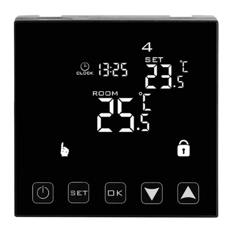
Poniżej przedstawiono identykację graczną przycisków panelu sterującego (wyświetlacza) termoregu-
latora. Przyciski te są multi-funkcjonalne, tzn. w zależności od stanu pracy termoregulatora, oraz różni-
cując czas utrzymywania dotyku możliwe jest wydawanie różnych komend termoregulatorowi. Poniżej
dokonano deskrypcji przycisków oraz szczegółowo omówiono dostępne z ich udziałem funkcje termo-
regulatora.
INSTRUKCJA OBSŁUGI I KONFIGURACJI TERMOSTATU
TERMOFOL TF-H2 Mark II
CHARAKTERYSTYKA I DANE TECHNICZNE
Dziękujemy za zakup naszego produktu. Liczymy, że będziecie Państwo zadowoleni z korzystania z ter-
moregulatora TERMOFOL TF-H2 Mark II. Jest to w pełni funkcjonalny sterownik instalacji i urządzeń
grzewczych, zapewniający najwyższy komfort obsługi oraz precyzyjne i użyteczne funkcje, które pozwolą
Państwu w pełni uzyskać kontrolę nad klimatem pomieszczeń. Poniżej przedstawiono wyświetlacz ter-
moregulatora oraz jego podstawowe parametry techniczne.
pobór mocy < 3 W • napięcie zasilające: 230 V AC 50/60 Hz • maksymalne natężenie przełączanego prądu: 20A • zakres
programowanej temp.: 1÷99 °C • fabryczny zakres programowanej temp.: 5÷35 °C • wewnętrzny czujnik temp. powie-
trza • dokładność: ±0.5 °C • stopień ochrony IP20 • zewnętrzny czujnik temp. podłogi: NTC • sterowanie manualne • moż-
liwość programowania • sposób montażu: natynkowy • kolor: biały • wymiary zewnętrzne: 86 mm x 86 mm x 37 mm
INSTALACJA TERMOSTATU, POŁĄCZENIA ELEKTRYCZNE
TERMOFOL TF-H2 Mark II to nowoczesny, wyposażony w panel LCD, programowalny termoregulator
przeznaczony do sterowania elektrycznymi systemami grzewczymi. Termoregulator odczytuje tempera-
turę z wewnętrznego i zewnętrznego czujnika temperatury, który jest dołączony w zestawie. Przed mon-
tażem, demontażem, czyszczeniem, dokonywaniem przeglądu, zawsze odłącz termoregulator od źródła
zasilania, np. wyłączając linię zasilającą w rozdzielni elektrycznej. Zapoznaj się z całą treścią niniejszej in-
strukcji przed rozpoczęciem instalacji termoregulatora. Na terenie RP, połączeń elektrycznych termore-
gulatora musi dokonać elektryk posiadający czynne uprawnienia SEP do robót elektroinstalacyjnych do 1
kV. Instalacja elektryczna zasilająca termoregulator powinna odpowiadać wymogom określonym w Roz-
porządzeniu Ministra Infrastruktury i Budownictwa w sprawie warunków technicznych jakim powinny
odpowiadać budynki i ich usytuowanie [DZ.U. z 7 czerwca 2019, poz. 1065] wraz z normami odniesienia.
Rys. 3 Przykład umiejscowienia termoregulatora
Instalacja termoregulatora powinna być zaplanowana w miejscu nienarażonym na kontakt z promie-
niami słonecznymi. Rysunek nr 2. przedstawia listwę zaciskową termoregulatora służącą do wykonania
podłączeń elektrycznych urządzenia z siecią elektryczną. Przewody należy podłączyć według podanego
schematu. Po zakończeniu instalacji i wykonaniu połączeń elektrycznych należy dokonać konguracji
systemu zgodnie z kolejnym punktem niniejszej instrukcji.
STEROWANIE – OPIS FUNKCJI PRZYCISKÓW STERUJĄCYCH
–
+
IKONY WYŚWIETLACZA – SPECYFIKACJA
Nr Symbol Rodzaj funkcji /
parametru Zakres wartości parametru /
opcji funkcji Wartość
fabryczna
1 SEN
Rodzaj czujników
0: tylko wewnętrzny czujnik temp. wł.
1: tylko zewnętrzny czujnik temp. wł.
2: włączony wewnętrzny i zewn. czuj-
nik temperatury
2
2 OSU
Ograniczenie maksymalnej
temp. czujnika zewnętrz-
nego
5–99 °C 28 °C
3 dlF Histereza zewnętrznego
czujnika temperatury 1–9 °C 2 °C
4SUH Maksymalna wartość pro-
gramowanej temp. 5–99 °C 35 °C
5 SUL Minimalna wartość progra-
mowanej temperatury 5–99 °C 5 °C
6 AdJ Kalibracja temperatury –5÷5 °C 0,0 °C
7 FrE
Funkcja zapobiegająca
zamarzaniu (tylko dla pod-
grzewania wody)
00: funkcja wyłączona
01: funkcja włączona 00
8 POn Zapamiętywanie ustawień
00: urządzenie nie zapamiętuje usta-
wień sprzed zaniku napięcia
01: urządzenie zapamiętuje ustawie-
nia sprzed zaniku napięcia
00
9 FAC Przywrócenie ustawień
fabrycznych
08: bez zmian
00: przywrócenie ustawień fabrycz-
nych
08
sensor
1,2m
Termoregulator jest przeznaczony do montażu
natynkowego.
1. Zdejmij czarną blachę znajdującą się z tyłu termoregu-
latora (przesuwając ją w dół) i przykręć ją do ściany.
2. Odkręć klapkę znajdującą się z tyłu
termoregulatora.
3. Dokonaj połączenia przewodów zgod-
nie ze schematem i przykręć klapkę.
Rys. 4
Rys. 5
Rys. 6
1. Zacisk podłączenia przewodu fazowego zasilania termoregulatora
2. Zacisk podłączenia przewodu neutralnego zasilania termoregulatora
3. Zacisk podłączenia przewodu neutralnego zasilania sterowanego odbiornika ( maty,folii grzewczej)
4. Zacisk podłączenia przewodu fazowego zasilania sterowanego odbiornika (maty,folii grzewczej)
5,6. Zaciski podłączenia zewnętrznego czujnika temp. NTC (biegunowość nie ma znaczenia)
Rys. 2
Rys. 1
4. Zamontuj termoregulator na ścianie.
Rys. 7
Przycisk włącz/wyłącz
Przycisk ten służy do zmiany trybu pracy z automatycznego na manualny. Naciśnięcie tego przyci-
sku przez około 5 sekund pozwala ustawić harmonogram pracy termoregulatora.
Dotknięcie tego przycisku pozwala na ustawienie aktualnej godziny i dnia tygodnia.
Przycisk kursora zwiększającego.
Wielokrotne dotknięcia zwiększają wartość temperatury zadanej.
Przycisk kursora zmniejszającego.
Wielokrotne dotknięcia zmniejszają wartość temperatury zadanej.
W przypadku pracy termoregulatora w trybie automatycznego harmonogramu, przyciski +/– umożliwiają
czasową korektę temperatury dla wykonywanego przez termostat aktualnego okresu automatycznego
harmonogramu.
tryb manualny tryb pracy
aktywny czujnik
powietrza
aktywny czujnik
zewnętrzny
dzień tygodnia
godzina temp. zdalna
aktualna
temperatura
6 okresów grzewczych
w trybie automatycz-
nego programu
USTAWIENIE HARMONOGRAMU PRACY
W stanie włączonego termoregulatora naciśnij przycisk przez około 5 sekund. Następnie za pomocą
+/- wybierz tryb harmonogramu (5+2, 6+1 lub 7-dniowy). Następnie ustaw żądaną temperaturę dla sze-
ściu okresów grzewczych. Aby przejść do kolejnego okresu naciskaj . Schemat powtórz również dla
dni weekendowych. Poniższa tabela przedstawia fabryczny cykl dnia.
Okres Ikona Rozpoczęcie
okresu Fabryczna temperatura
Dzień roboczy
106:00 20 °C
208:00 15 °C
311:30 15 °C
412:30 15 °C
517:30 22 °C
622:00 15 °C
Weekend
108:00 22 °C
223:00 15 °C
USTAWIENIA ZAAWANSOWANE
Aby przejść do ustawień zaawansowanych należy wyłączyć termoregulator. Następnie należy nacisnąć
„–” oraz przecisk włącz/wyłącz. Aby przejść do kolejnego parametru należy naciskać . Wartości zmie-
nia się za pomocą + oraz –.
+–
TF-H2 Mark II
1
2
3
4

Histereza czujnika zewnętrznego – dodatkowa informacja: limit wartości temperatury mierzonej przez
czujnik zewnętrzny wynosi 28 °C dla ustawień fabrycznych opcji zaawansowanych, a fabryczna wartość
histerezy czujnika zewnętrznego wynosi 2 °C. Gdy temperatura wzrośnie do 28 °C, termostat przestanie
zasilać sterowane urządzenie grzewcze.
Jeśli temperatura mierzona przez czujnik zewnętrzny spadnie do 26 °C, termostat ponownie zacznie
zasilać sterowane urządzenie grzewcze (tylko w sytuacji, gdy temperatura powietrza w pomieszczeniu
jest niższa od zadanej).
Kody błędów wyświetlane przez termostat.
Należy wybrać poprawną kongurację wbudowanego i zewnętrznego czujnika temperatury. Błędny wy-
bór lub usterka czujnika (awaria) spowoduje wyświetlenie na ekranie komunikatu o błędach. Wyświetla-
nie komunikatu o treści „Er” oznacza usterkę czujnika zewnętrznego temperatury.
Termostat nie zasili sterowanego urządzenia grzewczego do czasu usunięcia usterki!
INSTALACJA CZUJNIKA ZEWNĘTRZNEGO
Proszę umieścić peszel ochronny w wyżłobieniu podłogi z czujnikiem w środku. Koniec przewodu
ochronnego należy zaślepić. Przewód czujnika może być wydłużony do 50 metrów za pomocą innych
przewodów, jeśli to konieczne. Jeśli do przedłużania używamy kabla wielożyłowego, to nie używamy go
do zasilania (np. do zasilania kabla grzejnego), aby uniknąć zakłócenia sygnału napięciowego z sygnałem
ogrzewania termostatu. Należy wykonać pomiar rezystancji czujnika NTC. Pomiar rezystancji czujnika
NTC przeprowadzamy miernikiem uniwersalnym ustawionym na pomiar rezystancji w zakresie od 20
kΩ. Pomiar rezystancji czujnika podłogowego, ma charakter kontrolno-informacyjny i ma na celu, po-
dobnie jak pomiar rezystancji systemu grzewczego wykluczyć uszkodzenie przewodu przyłączeniowego
(np. jego naderwanie przy wciąganiu do peszla) czy też samego czujnika NTC. Orientacyjne wartości re-
zystancji w zależności od temperatury podłoża instalacji podano w poniższej tabeli. Tolerancja wartości
mierzonej na poziomie +/– 10%.
INFORMACJA:
Nie wolno podłączyć do termoregulatora urządzenia
grzewczego, którego moc nominalna przekracza 3600W.
Przekroczenie tej wartości grozi uszkodzeniem termore-
gulatora, a nawet pożarem przeciążonej instalacji. Pod-
łączenie urządzenia grzewczego mającego większą moc
niż 3600W wymaga zastosowania stycznika. Prawidłowa
konguracja i eksploatacja termoregulatora jest obliga-
-toryjnym warunkiem możliwości skorzystania z upraw-
nień wynikających z rękojmi i gwarancji udzielanej przez
producenta termoregulatora.
Temperatura powierzchni instalacji
°C
Rezystancja
kΩ
5 22
10 18
15 15
20 12
25 10
www.termofol.pl
biuro@termofol.pl
+48 (12) 376 86 00
POZNAJ INNE NASZE PRODUKTY:
TERMOFOL TF-WIFI Mark II TERMOFOL TF-H6 WIFI
INSTRUKCJA OBSŁUGI
W INNYCH JĘZYKACH
MIEJSCE INSTALACJI
DANE INSTALATORA
Nazwa rmy
Imię i Nazwisko
Adres (ulica, nr)
Kod Miejscowość
NIP Telefon
KARTA GWARANCYJNA
Data
Podpis instalatora Pieczątka instalatora

TF-H2 Mark II
The graphic identication of the thermoregulator control panel buttons (display) is presented below.
These buttons are multifunctional, i.e., depending on the operating status of the thermoregulator, and
by varying the duration of holding them down, it is possible to give various commands to the thermore-
gulator. The description of the buttons and the thermoregulator functions available with their use can
be found below.
OPERATING AND CONFIGURATION MANUAL
OF THERMOREGULATOR TERMOFOL TF-H2 Mark II
CHARACTERISTICS AND TECHNICAL DATA
Thank you for purchasing our product. We hope that you will enjoy using the TERMOFOL TF- H2 Mark
II thermoregulator. It is a fully functional controller of installations and heating devices providing the
highest comfort of use, as well as precise and useful functions that will allow you to fully control the
climate in your rooms. The display of the thermoregulator and its basic technical parameters are pre-
sented below.
power consumption < 3 W • supply voltage: 230 V AC 50/60 Hz • maximum amperage of switching current: 20A •
programmable temperature range 1+99 °C • factory range of programmed temperature.: 5+35 °C • internal air tem-
perature sensor accuracy: ±0.5 °C • protection class IP20 • external oor temperature sensor: NTC • manual control •
possibility of programming • mounting method: surface • color: white • dimensions: 86 mm x 86 mm x 37 mm
TERMOSTAT INSTALLATION, ELECTRIC CONNECTIONS
The TF-H2 Mark II is a modern, programmable thermoregulator equipped with LCD control panel in-
tended for controlling electric heating systems. The thermoregulator reads the temperature from the
built-in sensor and external temperature sensors, which is included in the kit along with the thermore-
gulator. Prior to its installation, disassembly, cleaning, inspection or change of the conguration, always
disconnect the thermoregulator from the power source, e.g., by switching o the power line in the elec-
tric switchboard. Read the entire contents of this manual before installing the thermoregulator. In the
territory of the Republic of Poland, the electric connections of the thermoregulator should be made by
an electrician holding a valid SEP license for electric installations up to 1 kV.
The electric installation supplying the thermoregulator should meet the requirements specied in the
Regulation of the Minister of Infrastructure and Construction on technical conditions to be met by buil-
dings and their location (Journal of Laws of 7 June 2019, item 1065) along with the reference standards.
Fig. 3 Example of thermoregulator location
The installation of the thermoregulator should be planned in a place not exposed to direct sunlight.
Figure 2 shows the thermoregulator terminal strip used for making electrical connections of the device
to the electric network. The cables must be connected as indicatedthe given scheme. After completing
the installation and making electrical connections, check the system guration in accordance with the
next section of this manual.
CONTROLLING – DESCRIPTION OF THE FUNCTIONS OF THECONTROL BUTTONS
–
+
DISPLAY ICONS – SPECIFICATION
No. Symbol Setting item Parameter setting function Factory
default
1
SEN Sensor control option
0: internal sensor
1: external sensor
2: internal control temperature and
external limit temperature
2
2 OSU Limit temperature value of
external sensor 5–99 °C 28 °C
3 dlF
Return dierence of limit
temperature value of exter-
nal sensor
1–9 °C 2 °C
4SUH Set upper limit temperature
value 5–99 °C 35 °C
5 SUL Set lower limit temperature
value 5–99 °C 5 °C
6 AdJ Measure temperature –5÷5 °C 0,0 °C
7 FrE Anti-freezing function (only
for water heating)
00: anti-freezing function close
01: anti-freezing function open 00
8 POn Power on memory 00: Power on no need memory
01: Power on need memory 00
9 FAC Factory default 08: no change
00: factory reset 08
sensor
1,2m
The thermoregulator is designed for surface
mounting.
1. Remove the black sheet on the back of the
thermoregulator (by moving it down) and
screw it to the wall.
1
2
3
4
2. Unload the ap on the back of the thermo-
regulator.
3. Make the connection of the wires accor-
ding to the diagram and screw the ap.
Fig. 4
Fig. 5
Fig. 6
1. Terminal for connecting for phase wire of thermoregulator power supply
2. Terminal for connecting the neutral wire of thermoregulator supply
3. Terminal for connecting the neutral wire of the controlled receiver (heating mat, heating foil)
4. Terminal for connecting the phase wire of the controlled receiver (heating mat, heating foil) supply
5, 6. Terminals for connecting the external temperature sensor NTC (polarity is irrelevant)
Fig. 2
Fig. 1
4. Mount the thermoregulator on the wall.
Fig. 7
Power ON/OFF button
This button is used to change the operating mode from automatic to manual. Pressing this button
for about 5 seconds allows you to set the thermoregulator work schedule.
Touching this button allows you to set the current time and day of the week.
Increasing cursor button. Repeated touches increase the value of the set temperature.
Decrease cursor button. Repeated touches decrease the set temperature value.
When the thermoregulator is operating in the automatic schedule mode, the buttons +/- allow for a
temporary temperature correction in respect of the current period of the automatic schedule of the
performed by the thermostat.
manual mode operating mode
active air
sensor
active external
sensor
day of the week
time set temperature
current temperature
6 heating periods
in the automatic
schedule mode
SETTING THE OPERATING SCHEDULE
When the thermoregulator is on, press the button for about 5 seconds. Then with +/– select schedu-
le mode (5+2, 6+1 or 7). Then set the desired temperature for the six periods heating. Presses to
move to the next period. Also repeat the schemefor weekend days.
Period Icon Default
Period Time
Default
Period Temperature
Working Day
106:00 20 °C
208:00 15 °C
311:30 15 °C
412:30 15 °C
517:30 22 °C
622:00 15 °C
Weekend
108:00 22 °C
223:00 15 °C
ADVANCED SETTINGS
To go to the advanced settings, turn o the thermoregulator. Then you should press - and the button on
/ o. To go to the next parameter, press . Values are changed with + and –.
+–

Hysteresis of the external oor sensor – additional information:
the limit of a temperature value measured by the external oor sensor is of 28 °C for the factory setting
of the advanced options and the factory value of the external oor sensor hysteresis is of 2 °C. When the
temperature rises to 28 °C, the thermostat stops supplying the controlled heating device and reminds
you of the high temperature alarm. If the temperature measured by the external oor sensor decreases
to 26 °C, the thermostat will start supplying the controlled heating device again (only if the air temperatu-
re in the room is lower than the set temperature). The thermostat will not supply power to the controlled
heating device until the error has been corrected!
INSTALLATION OF THE EXTERNAL SENSOR
Place the protective conduit in the groove in the oor with the sensor inside. The end of the protective
conductor must be sealed. The sensor wire can be extended up to 50 meters with other wires, if neces-
sary. If a multi-core cable is used for the extension, it must not be used for power supply (e.g., for the
heating cable) in order to avoid interference of the voltage signal with the heating signal of the thermo-
stat. The resistance of the NTC sensor must be measured.
The resistance of the NTC sensor is measured with a universal meter set to measure resistance in the
range from 20 kΩ. The measurement of the oor sensor resistance is of control and informational natu-
re, and its purpose is, similarly to the measurement of the heating system resistance, to exclude damage
of the connection wire (e.g., its tearing when pulling it into the conduit) or the NTC sensor itself. Approxi-
mate resistance values, depending on the temperature of the installation base, are given in the following
table. Tolerance of the measured value is +/– 10%.
INFORMATION:
It is forbidden to connect a heating device which nomi-
nal output power exceeds 3600W to the thermoregu-
lator. Exceeding this value may cause damage to the
thermoregulator or even re in the over-loaded system.
Connection of a heating device with power greater than
3600W requires the use of a contactor. Correct congu-
ration and operation of the thermoregulator is obligato-
ry condition to be able to make use of the statutory war-
ranty and warranty rights granted by the manufacturer
of the thermoregulator.
Temperature of installation surface
°C
Resistance
kΩ
5 22
10 18
15 15
20 12
25 10
www.termofol.pl
biuro@termofol.pl
+48 (12) 376 86 00
DISCOVER OUR OTHER PRODUCT:
TERMOFOL TF-WIFI Mark II TERMOFOL TF-H6 WIFI
Installation manual
in dierent languages
ERROR CODES DISPLAYED BY THE THERMOSTAT
The correct conguration of the built-in and external oor temperature sensor must be selected in
advanced settings (SEN). Incorrect selection or a sensor failure (malfunction) will cause an error messa-
ge to appear on the screen. Displaying ‘Er’ indicates a malfunction of the external temperature sensor.
The thermostat will not supply power to the controlled heating device until the error has been corrected!
PLACE OF INSTALLATION
FITTER’S DETAILS
Name of com-
pany
Forename
and surname
Address
(street, no.)
Postal
code Locality
NIP Tel.
WARRANTY CARD
Date
Fier’s signature Fier’s stamp
Table of contents
Languages:
Other TERMOFOL Controllers manuals
Popular Controllers manuals by other brands
LEGRAND
LEGRAND Wattstopper LMRC-611MCC quick start guide
ALDEN
ALDEN SPS 180 AGM quick start guide
Ranco
Ranco O10 Installation data
Rail King
Rail King Z-750 manual

Special Projects Group
Special Projects Group SP-500 installation guide
KROHNE
KROHNE OPTISENS CAC 050 R Installation and operating instructions
