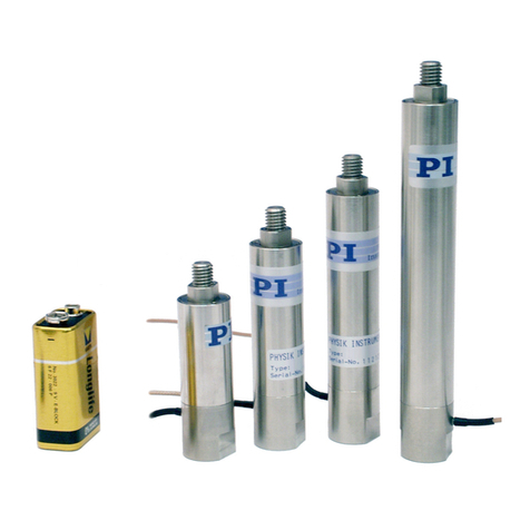
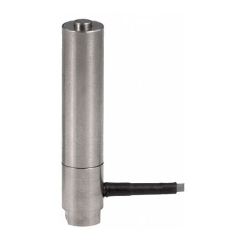
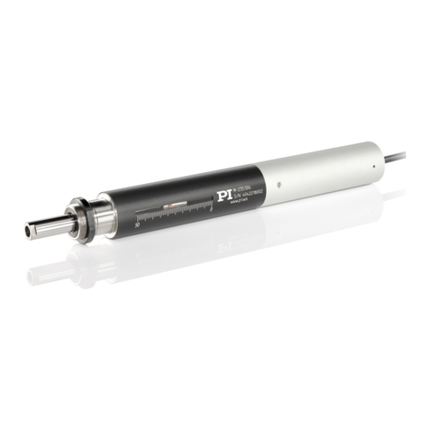
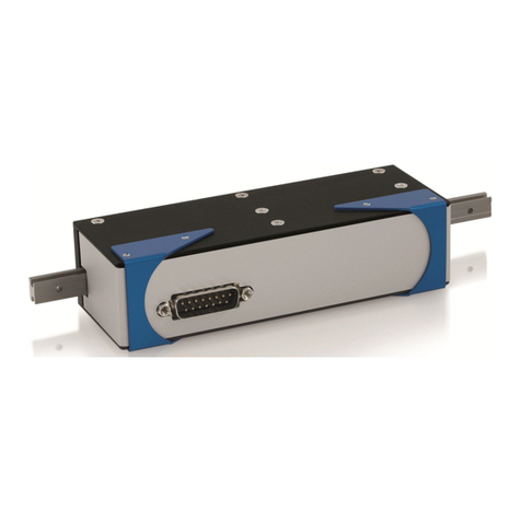
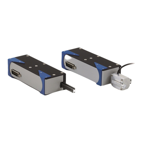
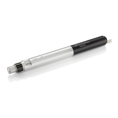
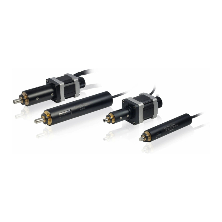
PI M-238 User manual

PI miCos GmbH, Freiburger Strasse 30, 79427 Eschbach, Germany
Phone +49 7634 5057-0, Fax +49 7634 5057-99, Email info@pimicos.com, www.pi.ws
MP77E
M
-238 High-Load Linear Actuator
User Manual
Version: 1.1.0
Date: 11/4/2020
This document describes the following high
-load-
linear actuators with 50 mm travel range:
M-238.5PG
with DC gear motor with PWM power amplifier
(ActiveDrive), with rotary encoder
M-238.5PL
with DC gear motor with PWM power amplifier
(ActiveDrive), with linear encoder

The following company names and brands are registered trademarks of Physik Instrumente (PI) GmbH & Co.
KG:
PI®, NanoCube®, PICMA®, PIFOC, PILine®, NEXLINE®, PiezoWalk®, PicoCube®, PiezoMove®, PIMikroMove,
NEXACT®, Picoactuator®, PInano®, NEXSHIFT®, PITOUCH®, PIMag®, PIHera, Q-Motion®
© 2020 Physik Instrumente (PI) GmbH & Co. KG, Karlsruhe, Germany. The text, photographs, and drawings in
this manual are protected by copyright. With regard thereto, Physik Instrumente (PI) GmbH & Co. KG reserves
all rights. The use of any text, images, and drawings is permitted only in part and only when indicating the
source.
Original instructions
First print: 11/4/2020
Document number: MP77E, ASt, Version 1.1.0
Subject to change. This manual is superseded by any new release. The latest release is available for download
from our website (p. 2).

1About this Document 1
1.1 Objective and Target Group of this User Manual ...................................................... 1
1.2 Symbols and Typographic Conventions...................................................................... 1
1.3 Other Applicable Documents ..................................................................................... 2
1.4 Downloading Manuals................................................................................................ 2
2Safety 3
2.1 Intended Use .............................................................................................................. 3
2.2 General Safety Information........................................................................................ 3
2.2.1 Organizational Measures............................................................................... 3
3Product Description 5
3.1 Model Overview ......................................................................................................... 5
3.2 Product View .............................................................................................................. 5
3.2.1 Elements of the M-238 .................................................................................. 5
3.2.2 Type plate ...................................................................................................... 6
3.3 Scope of Delivery........................................................................................................ 6
3.4 Suitable Electronics .................................................................................................... 6
3.5 Technical Features...................................................................................................... 7
3.5.1 Integrated PWM amplifier............................................................................. 7
3.5.2 Encoder.......................................................................................................... 7
3.5.3 Limit Switches................................................................................................ 7
3.5.4 Reference Switch........................................................................................... 7
4Unpacking 9
5Installing 11
5.1 General Notes on Installing ...................................................................................... 11
5.2 Providing a Suitable Mechanical Mounting and Installation Environment.............. 12
5.3 Installing the M-238 into a Mechanical Mounting................................................... 13
5.4 Connecting the M-238.............................................................................................. 14
6Starting 15
6.1 General Notes on Starting........................................................................................ 15
6.2 Starting and Operating the M-238 ........................................................................... 16
Contents

7Maintenance 17
7.1 Lubricating the M-238 .............................................................................................. 17
7.2 Cleaning the M-238 .................................................................................................. 17
8Troubleshooting 19
9Customer Service Department 21
10 Technical Data 23
10.1 Specifications............................................................................................................ 23
10.1.1 Data Table.................................................................................................... 23
10.1.2 Maximum Ratings........................................................................................ 24
10.1.3 Ambient Conditions and Classifications ...................................................... 24
10.1.4 Limit Switch Specifications .......................................................................... 25
10.1.5 Reference Switch Specifications.................................................................. 25
10.2 Dimensions ............................................................................................................... 25
10.3 Pin Assignment ......................................................................................................... 26
10.3.1 Drive connector ........................................................................................... 26
10.3.2 Voltage connector ....................................................................................... 27
10.4 Measured Curves...................................................................................................... 27
11 Old Equipment Disposal 29
12 EU Declaration of Conformity 31

1 About this Document
M-238 High-Load Linear Actuator MP77E Version: 1.1.0 1
1.1 Objective and Target Group of this User Manual
This user manual contains the information necessary for using the M-238 as intended.
Basic knowledge of closed-loop systems, motion control concepts, and applicable safety
measures is assumed.
1.2 Symbols and Typographic Conventions
The following symbols and typographic conventions are used in this user manual:
CAUTION
Dangerous situation
Failure to comply could lead to minor injury.
Measures for avoiding the risk.
NOTICE
Dangerous situation
If not avoided, the dangerous situation will result in damage to equipment.
Measures for avoiding the risk.
INFORMATION
Information for easier handling, tricks, tips, etc.
Symbol/
Label
Meaning
1.
2.
Action consisting of several steps with strict sequential order
Action consisting of one or more steps without relevant sequential order
Lists
p. 5 Cross-reference to page 5
RS-232 Label on the product indicating an operating element
1
About this Document

1 About this Document
2 Version: 1.1.0 MP77E M-238 High-Load Linear Actuator
1.3 Other Applicable Documents
The devices and software tools from PI mentioned in this documentation are described in
separate manuals.
Document number Document type Product
MP122EK Short Instructions Linear actuators
Manual Manual for the electronics
1.4 Downloading Manuals
INFORMATION
If a manual is missing or problems occur with downloading:
Contact our customer service department (p. 21).
Downloading manuals
1. Open the website www.pi.ws.
2. Search the website for the product number (e.g., F-238).
3. Click the corresponding product to open the product detail page.
4. Click the Downloads tab.
The manuals are shown under Documentation.
5. Click the desired manual and fill out the inquiry form.
The download link will then be sent to the email address entered.

2 Safety
M-238 High-Load Linear Actuator MP77E Version: 1.1.0 3
2.1 Intended Use
The M-238 is a laboratory device as defined by DIN EN 61010-1. It is intended for indoor use
and use in an environment which is free of dirt, oil, and lubricants.
According to its design, the M-238 is intended for positioning, adjusting and shifting loads in
one axis at various velocities. The M-238 can be mounted horizontally or vertically.
It is only possible to use the M-238 as intended when it is installed and connected properly, and
only in conjunction with a suitable controller. The controller must be able to read and process
the signals from reference and limit switches, and from the incremental position sensors. The
controller is not included in the scope of delivery of the M-238.
2.2 General Safety Information
The M-238 is built according to state-of-the-art technology and recognized safety standards.
Improper use may result in personal injury and/or damage to the M-238.
Use the M-238 only for its intended purpose, and only when it is in perfect technical
condition.
Read the user manual.
Eliminate any malfunctions that may affect safety immediately.
The operator is responsible for the correct installation and operation of the M-238.
2.2.1 Organizational Measures
User manual
Always keep this user manual together with the M-238.
If the user manual is lost or damaged, please contact our customer service (see p.
The latest versions of the user manuals are available on our website (p. 2) for
download.
Add all information from the manufacturer such as supplements or technical notes to
the user manual.
If you give the M-238 to other users, include this user manual as well as all other
relevant information provided by the manufacturer.
Do the work only if the user manual is complete. Missing information due to an
incomplete user manual can result in minor injury and damage to equipment.
Install and operate the M-238 only after you have read and understood this user
manual.
2
Safety

2 Safety
4 Version: 1.1.0 MP77E M-238 High-Load Linear Actuator
Personnel qualification
The M-238 may only be installed, started, operated, maintained, and cleaned by authorized and
appropriately qualified personnel.

3 Product Description
M-238 High-Load Linear Actuator MP77E Version: 1.1.0 5
3.1 Model Overview
Model Description
M-238.5PG High-load linear actuator, 400 N, 50 mm, DC gear motor, ActiveDrive
M-238.5PL High-load linear actuator, 400 N, 50 mm, DC gear motor, ActiveDrive, direct
position measuring
3.2 Product View
3.2.1 Elements of the M-238
Elements of the M-238
Labeling Type Function
Controller D-sub 15 (m) (p. 26) Drive connector: Connects the M-238 to the
electronics
24 V DC Mini XLR 3-pole (m) (p.
27)
Connector for the power supply
3
Product Description

3 Product Description
6 Version: 1.1.0 MP77E M-238 High-Load Linear Actuator
3.2.2 Type plate
Labeling Description
Manufacturer's logo
M-238.5PL Product name (example); the characters after the period refer
to the model
415002159 Serial number (example), individual for each M-238
Meaning of each position (from the left):
1 = internal information,
2 and 3 = year of manufacturer,
4 to 9 = consecutive numbers
Warning sign "Pay attention to the manual!"
Country of origin: Germany Country of origin
CE conformity mark
WWW.PI.WS Manufacturer's address (website)
Old equipment disposal
M-238 Product series
3.3 Scope of Delivery
Order number Components
000023194 24 V 120 W wide input range power supply, with barrel connector socket
3763 Power cord
K050B0002
Power adapter, barrel connector 5.5 mm x 2.1 mm to mini XLR3 (f)
MP122EK Short instructions for linear actuators
3.4 Suitable Electronics
The M-238 must be connected to suitable electronics. The following electronics are suitable:
Product number
Description
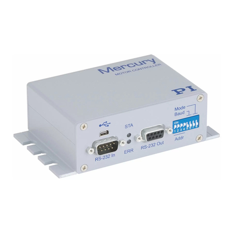
C-863 Mercury DC motor controller
C-884 DC motor controller
The required PC software is included in the scope of delivery of the electronics from PI. The
operation of the controllers is described in the corresponding user manuals.
Note that the cables required for connecting the M-238 to the electronics must be ordered
separately.
To order, contact the customer service department (p. 21).

3 Product Description
M-238 High-Load Linear Actuator MP77E Version: 1.1.0 7
3.5 Technical Features
3.5.1 Integrated PWM amplifier
The M-238 model is equipped with a PWM amplifier ("ActiveDrive concept").
The integrated PWM amplifier for ActiveDrive DC motors only receives control signals from the
control electronics, whereas the supply voltage is provided via an external power adapter. The
higher motor performance allows better dynamics.
3.5.2 Encoder
The M-238.5PG model is equipped with a rotary encoder. A rotary encoder is implemented at a
rotating point in the drivetrain, e.g., the motor shaft. The encoder provides a certain number of
signals for each change of position. The controller counts the encoder signals, the so-called
pulses, in order to determine the relative position. The M-234 must be moved to a limit or
reference switch in order to measure the absolute position (referencing).
The M-238.5PL model is equipped with an optical linear encoder. Optical linear encoders
measure the actual position directly and therefore eliminate drive errors such as nonlinearity,
backlash or elastic deformation.
The resolution of the encoders can be found in the data table (p. 23).
3.5.3 Limit Switches
The limit switches are sensors at each end of the travel range that enable the electronics to
abort motion in order to prevent the pusher from colliding with the mechanical hard stop.
The M-238 is equipped with noncontact Hall effect limit switches (p. 25).
3.5.4 Reference Switch
The reference switch is a sensor whose fixed position serves as the reference point for
incremental sensor signals.
The M-238 is equipped with a magnetic (Hall effect), direction-sensing reference switch (p. 25)
positioned approximately at the midpoint of the travel range. This sensor sends a TTL signal
that indicates whether the positioner is on the positive or negative side of a specified point.
Both the rising and falling edges of the signal can serve as reference (accuracy approx. 0.5 μm,
depending on the controller). The difference between the reference points is approx. 0.2 to 0.4
mm when approached from the positive or negative direction.
The commands that use the reference signal are described in the user manual for the
controller.


4 Unpacking
M-238 High-Load Linear Actuator MP77E Version: 1.1.0 9
1. Unpack the M-238 with care.
2. Compare the contents with the items listed in the contract and the packing list.
3. Inspect the contents for signs of damage. If there is any sign of damage or missing parts,
contact PI immediately.
4. Keep all packaging materials in case the product needs to be returned.
4
Unpacking


5 Installing
M-238 High-Load Linear Actuator MP77E Version: 1.1.0 11
5.1 General Notes on Installing
NOTICE
Damage due to mechanical stress on the cable!
The cable will break from excessive bending or crushing. A broken cable will lead to failure of
the M-238 or damage to the actuator or the electronics.
Install the M-238 so that the cable cannot be bent or crushed too strongly.
NOTICE
Increased friction!
Lateral forces acting on the pusher of the linear actuator increase the friction of the internal
drive components. Increased friction impairs the motion of the pusher and increases wear on
the drive components.
Avoid lateral forces on the tip and on the pusher of the M-238.
NOTICE
M-238 heating up during operation!
The heat produced while operating the M-238 can affect your application.
Install the M-238 so that the application is not impaired by dissipating heat.
5
Installing

5 Installing
12 Version: 1.1.0 MP77E M-238 High-Load Linear Actuator
5.2 Providing a Suitable Mechanical Mounting and Installation
Environment
Example of installing a linear actuator
A suitable mechanical mounting and installation environment are necessary for the proper use
of the actuator.
Make sure that the following conditions have been met:
−Material and statics of the mounting are designed so that the static and dynamic
forces that occur can be safely and continuously managed.
−The dimensions of the mounting are adapted to the dimensions of the actuator (see
dimensions, (p. 25).
−The intended motion of the pusher and the load must not be inhibited by the
dimensions of the installation environment.
Take into account the following specifications as well when planning the application
and installing the actuator:
−Tip dimensions (see Dimensions (p. 25))
−Travel range (see data table (p. 23))
−Space requirements for bend-free and proper guiding of the connecting cable and
additional motor cables
−Length of the connecting cable and the motor cable
If the limit switches of the actuator cannot be reached with the planned minimum and
maximum displacements: Make sure that the actuator and the load only move within
the planned range. Suitable measures:
−Corresponding programming of the controller
−Emergency off switch
−Automatic shutdown systems
In accordance with the legal regulations, avoid or label danger areas resulting from the
installation of the actuator and from use (e.g., risk of crushing in the case of heavy
moving loads, fast actuator motion and/or high drive torques).

5 Installing
M-238 High-Load Linear Actuator MP77E Version: 1.1.0 13
5.3 Installing the M-238 into a Mechanical Mounting
INFORMATION
To achieve an optimal repeatability, the mounting shaft must not have any backlash.
When assembling, make sure that the actuator and the mechanical mounting have been
connected perfectly.
We recommend installing the actuator into the mounting with a clamp connection. The
following instructions refer to this case.
Clamp connection (schematic)
1. Mechanical mounting
2. Sleeve
3. Mounting nut
4. Mounting shaft with thread
5. Pusher with tip
Requirements
You have read and understood the general notes on installation (p. 11).
You have provided your application with a suitable mounting for the mounting shaft of
the actuator (p. 12).
Tools and Accessories
Open-end wrench AF 41
Installing the Actuator
1. Loosen the mounting nut on the mounting shaft of the actuator.
2. Position the actuator in the mounting of your application.

5 Installing
14 Version: 1.1.0 MP77E M-238 High-Load Linear Actuator
3. If necessary, put a suitable flat washer or a suitable spring washer onto the mounting
shaft.
4. Turn the mounting nut a few times by hand into the thread of the mounting shaft.
5. To clamp the actuator in the mounting, tighten the mounting nut using the open-end
wrench until you feel a resistance. The torque may not exceed 2 Nm!
6. Check that the actuator is fixed firmly in the mounting.
5.4 Connecting the M-238
NOTICE
Damage if the wrong controller is connected!
Connecting a linear actuator to an unsuitable controller can damage the linear actuator or
controller.
Connect the M-238 to a DC motor controller only.
Requirements
You have read and understood the general notes on installation (p. 11).
You have read and understood the user manual for the electronics.
You have installed the electronics properly.
The electronics are switched off.
Tools and Accessories
Suitable electronics (p. 6)
Cable set suitable for the electronics used
Wide input range power supply with power adapter and power cord (included in the
scope of delivery, p. 6)
If necessary: Suitable screwdriver for the locking screws of the connectors
Connecting the Actuator
1. If necessary: Remove the ESD protective caps from the M-238's connectors.
2. Connect the electronics:
a) Connect the M-238's drive plug to the drive socket on the electronics.
b) Secure the connectors against unintentional removal.
3. Connect the power adapter:
a) Connect the power cord to the M-238's power connector with the help of the
power adapter.
b) Connect the power cord to the power adapter.

6 Starting
M-238 High-Load Linear Actuator MP77E Version: 1.1.0 15
6.1 General Notes on Starting
CAUTION
Unintentional movement of the linear actuator when switching the controller on!
Failure to comply could lead to minor injury.
Do not place any objects in areas where they could be caught by moving parts.
Keep a safe distance from the motion range of the linear actuator.
NOTICE
Damage due to the pusher hitting the hard stop!
When the limit switches are deactivated, the motion of the pusher is stopped by the hard stop
and the M-238 could be damaged.
Do not deactivate the limit switches in the software.
Test the function of the limit switches at low velocities only.
NOTICE
Damage or considerable wear due to high acceleration!
High acceleration could cause considerable wear and damage the mechanics.
Stop motion immediately if a controller malfunction occurs.
Make sure that the end of the travel range is approached at low velocity.
Set the control signal so that the moving part does not stop abruptly or try to continue
motion at the end of the travel range.
Determine the maximum velocity for your application.
6
Starting

6 Starting
16 Version: 1.1.0 MP77E M-238 High-Load Linear Actuator
6.2 Starting and Operating the M-238
Requirements
You have read and understood the general safety instructions (p. 3).
You have installed the M-238 properly (p. 11).
You have read and understood the user manual for the electronics.
If a digital controller is used: You have read and understood the manual for the PC
software used.
The electronics and if required, the PC software, have been installed (refer to the user
manual for the electronics).
Starting and Operating the Actuator
1. Plug the power cord of the power adapter into the power socket.
2. Start the electronics (refer to the user manual for the electronics).
3. Configure the electronics for the M-238 during startup:
−If you are using a digital controller from PI: In the PC software, select the entry in
the positioner database that matches the M-238 model exactly.
−If you are using electronics from another manufacturer: Configure the electronics
according to the parameters of the M-238 (p. 23).
4. Start a few motion cycles for testing purposes (refer to the user manual for the
electronics).
Table of contents
Other PI Controllers manuals
Popular Controllers manuals by other brands

Converging Systems
Converging Systems ILC-100 Series quick start guide

dixell
dixell Emerson iChill IC100CX EVO Quick reference guide

Pelltech
Pelltech DK8002A1 instruction manual

LSI
LSI MegaRAID SATA 300-8XLP Quick installation guide

Dantel
Dantel PointMaster TL1 installation guide

SpaGuts
SpaGuts VS300FC5 installation instructions