enertik BSSC4-29-1000-110V User manual

CONTENTS
1.Safety------------------------------------------------------------------------------3
2.Technical Specificationy--------------------------------------------------------4
3.Protect Function Manualy------------------------------------------------------4
4.Installation Guidey----------------------------------------------------------------5
5.Operating Board Instructiony--------------------------------------------------8
6.Angle of installation of the solar panel---------------------------------------10
7.Test Runningy-------------------------------------------------------------------11
8.Maintanance Methody----------------------------------------------------------11
9.Error Code and Meaningsy-----------------------------------------------------12
Attention:
1.Please carefully check the manual before installation.
2.The only usage of the product is to control the matched DC solar pumps.
Pump Controller Manual
BSSC4-29-1000-110V
BSSC4-53-10000110V
BSSC4-88-1000-110V
BSSC4-60-1500-150V
BSSC4-77-1500-150V
BSSC4-130-1500-150V
BSSC4-47-2200-220V

1.Safety
1.1 Before Power On
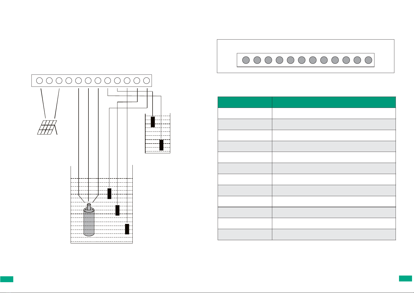
●Make sure the terminal wire connections are correct,“P+”、“P-”are for
panel connection,“1”、“2”、“3”for pump connection,wrong connection will
lead to controller damage.
●The voltage of panel system is not allowed to exceed the open-circuit
voltage of controller , avoid to use same power supply with strong
interference equipment , otherwise it will damage the controller.
●Match correct pump power with controller.
●Ensure the insulation of MOSFET and aluminum board during the
installation.
1.2 In running
●When the system is running,it is not allowed to disconnect the connection
between pump and controller,other wise it may damage the pump motor and
controller.
●When the system is running,do not tough or exam the The parts of the circuit
board or signal.
●Do not tough the radiator or any heat parts,in case of burns.
●Unprofessinal operators are not allowed to operate or exam the controller.
2.Technical Specification
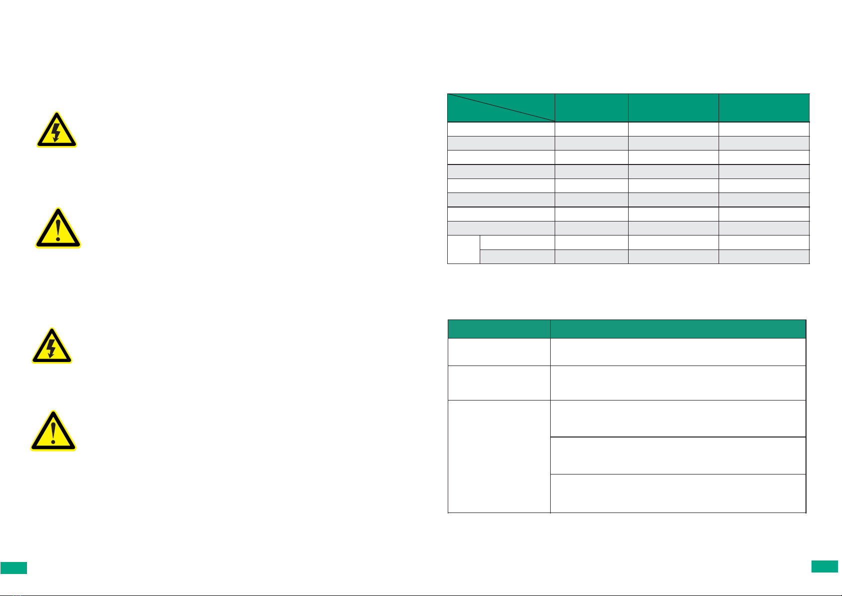
Table 1 Specification
150V 220V 300V
Rated Voltage 150VDC 220VDC 300VDC
Rated Current 10A 10A 10A
Max working Current 12A 12A 12A
Min working Current 1.3A 1.3A 1.3A
Open circuit voltage input >170VDC >272VDC >340VDC
Open circuit voltage Max 250VDC 350VDC 450VDC
Open circuit voltage Min 90VDC 150VDC 220VDC
Max Power 1.5KW 2.2KW 3KW
Current
Overload 15±0.5A 15±0.5A 15±0.5A
Over current 32±0.5A 32±0.5A 32±0.5A
Model
Specification
3.Protect Function Manual
Table 2 Protect Function Instruction
Protection Manual
Protection of opposite
connection
Solar Panel “PV+”“PV-”polarity are opposite connected, controller can
continue working after adjust.
Load over current and short
circuit protection
If the load current is more than15A and longer than 10s,the controller will
be in protection mode; If more than 32±0.5A,the controller will stop
working immediately. Try to re-start the controller 15mins later.
Weak Power Protection
(Details See Table 4)
50V: The working current smaller than 1.3A;Solar Panel input voltage
smaller than 60VDC or bigger than 250VDC;Come into Protection mode
.
Try to re-start the controller 6mins later.
220V: The working current smaller than 1.3A;Solar Panel input voltage
smaller than 110VDC or bigger than 350VDC;Come into Protection
mode. Try to re-start the controller 6mins later.
300V: The working current smaller than 1.3A;Solar Panel input voltage
smaller than 220VDC or bigger than 450VDC;Come into Protection
mode. Try to re-start the controller 6mins later.
03 04

4. Installation Guide
4.1 Wire connection
Typical wire connection as below pictures:
P+ ETH P- NC 1 2 3 COM2
TH
COM1
WL
WH
solar panel
4.2 Terminal Instruction:
Table 3 Terminal instruction
Terminal Instruction
P+ Anode of solar panel
ETH Earth
P- Cathode of solar panel
NC Blank
1 Connect with Pump motor Wire 1
2 Connect with Pump motor Wire 2
3 Connect with Pump motor Wire 3
COM2 Low level of Tank(Water level sensor)
TH High level of Tank(Water level sensor)
COM1 Public wire of Well(Water level sensor)
WL Low level of Well(Water level sensor)
WH High level of Well(Water level sensor)
P+ ETH P- NC 1 2 3 COM2
TH
COM1
WL
WH
05 06

4.3 Instruction of water level sensors
Tank water level sensor: The tank water level senor is used to detect the water level of
tank.Once the tank is full,the sensor will stop the system.When installation,connect“COM2”at
the bottom of tank,connect“TH”at the top of tank.Once the water level is full,the system will
stop in 8s;once the tank is empty,the system will re-start to work in 5mins.
4.4 Light Instruction
Table 4 150V/220V/300V Light Instruction
Lighting Light Situation
Light Situation Instruction Recover
Time
150V 220V 300V
POWER Stay On System Normal
MPPT Flashing MPPT mode on
ERR_I
Stay On T≥15S
,
I≥15A;
T≥15min
Flashing I≥32A.
Stay On A:Vsolar≤50
V
B:I≤1.3A.
A:Vsolar≤110
V
B:I≤1.3A.
A:Vsolar≤220
V
B:I≤1.3A. T≥6min
Flashing Vsolar≥250V Vsolar≥350V Vsolar≥450V
Tank_F
Stay On The tank is full
Flashing Wait for pumping up T≥5min
WELL_L
Stay On No water in the well
Flashing Wait for pumping up T≥30min
AN - Meaningless for Now
Well water level sensor: The well water level sensor is used to detect the water level of
well.Once the well is empty, the sensor will stop the system .When installaiton,connect
“COM1”at the bottom of well,connect“WH” higher than “COM1”.Once the well is empty,the
system will stop in 10s; once the water level is higher than “WH”level,the system will re-start
to work in 30mins.
5.Operating Board Instruction
5.1 Operating Board
C h a r t 2 O p e ra t in g B o a rd
5 . 2 B u t to n I n s t r u ct io n
START VAP NEH STOP
Ta b le 5 B u tto n F u n ct io n h
Button Instruction
“Start” The pump will start running immediately, no 1min delay
when power connecting any more
“V/A/P“ Display the system parameters sequently,
voltage/current/power
“n/E/h“ Display the system parameters sequently, speed/ fault
code/system operate time
“Stop“ Stop the pump immediately, and the pump must be reboot
manually
07 08

5.3 Digital Display Manual
Ta b le 5 D ig ita l D is p la y S ho w s
Digital Display Shows Instruction
Decimal points are lit successively an
d
circularly
1.When electrified, the system enter into the defaul
t
energy saving mode
2.After 1 minute of no button operation, the system
enter into the energy saving model
“N” is displayed on screen Press “ STAR” button and will enter into the startup
mode
“U XXX” is displayed on screen The first time to press “V/A/P” button, and will
display the system voltage
“C XX.X” is displayed on screen The second time to press “V/A/P” button, and will
display the over-load current
“P XXX” is displayed on screen The third time to press “V/A/P” button, and will
display the motor power
“XXXX” is displayed on screen
The first time to press “n/E/h” button and a number
displayed on screen. Calculate the motor speed
according to this number. Speed=number/pole pair
s
(note: pole pairs= number of poles/2)
“E-XXX” is displayed on scree System abnormal(more details refer to Error Code)
“X” is displayed on screen Display the motor run time
“N XXX” is displayed on screen Press “STOP” button to enter into the stop mode
6. Angle of installation of the solar panel
Use the following graphics to help determine your optimal mounting angle. If you are located
in the Northern hemisphere, face your panels south, and tilt back to an angle equal to your
latitude. The opposite is required if located in the Southern Hemisphere.This is a standard
year-round default position. For seasonal positioning, please see the chart below.
Latitude Year Round Tilt Year Round Tilt Winter Tilt
50 60 55 65
45 55 50 60
40 45 40 50
35 40 35 45
20 20 15 25
+ 6 0°
+ 3 0°
0°
- 3 0°
- 6 0°
+ 9 0°
+ 6 0°
+ 3 0°
0°
- 3 0°
- 6 0°
- 9 0°
L A T I T U D E
09 10

7.Test Running
7.1 Key check project before test running
● Set all the terminal screws tight before running.
● Check all the connection of the terminal.
● Make sure no short circuit phenomenon.
7.2 Test running method
According to “Installation Guide”,make COM1 and WH short circuit;The system situation and
the light as follow table:
NO. Light System Situation
1 All the lights flash once Power on
2 “POWER”light is on System starts to self-check
3 “POWER + MPPT”light on Pump starts to run
Remark:1、If water level sensors are not used,make COM1 and WH short circuit to run the
system.
8.Maintanance Method
8.1 Regular maintanance project
● Every panel’s output voltage is in normal range.
● The tightness of terminal screws.
● Check if there are any dust/iron scrap/mordant liquidin controller.
● Check if there are any noise or shaking of the pump when the system is on.
8.2 Attentions during the maintanance
●Disconnect the input power of controller before maintanance;
●The demounted metal spare parts are not allowed to put into controller,it will lead to open-
circuit of controller;
●Keep the controller clean after maintanance,avoid any dust or liquid invade into the
controller.
9. ERROR CODE AND MEANING
E001: Current Protection
E002:Voltage Protection
E003:Current+Voltage Protection
E004: Tank Protection
E005: Current+Tank Protection
E006: Voltage+Tank Protection
E007: Current+Voltage+Tank Protection
E008: Low level Protection
E009: Low level+Current Protection
E010: Low level+Voltage Protection
E011: Low level+Current+Voltage Protection
E012: Tank+Low level Protection
E013: Tank+Low level+Current Protection
E014: Tank+Low level+Voltage Protection
E015: Tank+Low level+Current+Voltage Protection
E016: Data error
E032: Verify and Error
E064: Communications Blackout
11 12
This manual suits for next models
6
Table of contents
Other enertik Controllers manuals