Terumo BCT T-SEAL MOBILE User manual
LCT-7010en 12/2015

2
INTRODUCTION
Every effort has been made to ensure that the information in this document is correct, but
we make no guarantee to this effect and would appreciate any observations regarding the
contents of this document. We may make improvements and alterations to the instrument
and these changes will be incorporated in new issues of this publication when practicable.
Print: Uffe Tryckare, Upplands Väsby, 2015

3
INTRODUCTION
CONTENTS
1INTRODUCTION ........................................................................................... 4
2SYMBOLS/MARKINGS DESCRIPTION ......................................................... 5
3WARNINGS AND CAUTIONS ........................................................................ 6
4SPECIFICATIONS, PARTS AND ACCESSORIES ............................................7
4.1 Specifications.............................................................................................................................. 7
4.2 Parts .............................................................................................................................................8
4.3 Accessories ................................................................................................................................9
4.4 User Interchangeable Parts .....................................................................................................9
5INSTALLATION............................................................................................ 10
5.1 Unpacking and Inspection ..................................................................................................... 10
5.2 Environmental Requirements................................................................................................ 10
5.3 Installation Procedure ..............................................................................................................11
6FUNCTIONAL DESCRIPTION....................................................................... 12
6.1 Description of Sealing ............................................................................................................. 13
6.2 Description of Equipment....................................................................................................... 13
6.3 Checking the Battery unit....................................................................................................... 14
7OPERATING INSTRUCTIONS....................................................................... 15
7.1 Preparation before Use .......................................................................................................... 15
7.2 How to Seal Tubes .................................................................................................................. 15
7.3 If the Sealer Doesn´t Start....................................................................................................... 16
7.4 LED indications......................................................................................................................... 16
8TROUBLESHOOTING .................................................................................. 17
8.1 Battery Unit ............................................................................................................................... 17
8.2 Hand Unit................................................................................................................................... 18
9CLEANING .................................................................................................. 19
9.1 Battery unit................................................................................................................................ 19
9.2 Hand Unit.................................................................................................................................. 20
10 WARRANTY AND SERVICE ......................................................................... 21
10.1 Warranty .................................................................................................................................... 21
10.2 Service ....................................................................................................................................... 21
10.3 Product Disposal..................................................................................................................... 22
11 EMC TABLES ............................................................................................. 23
12 DECLARATION OF CONFORMITY .............................................................. 27

4
INTRODUCTION
1INTRODUCTION
This chapter contains a description and specifications of the T-SEAL MOBILE, a Portable
Battery sealer from Terumo BCT.
T-SEAL MOBILE is a fully automatic system for sealing PVC or EVA tubes, especially for tubes
in blood pack systems. Following the sealing procedure the tube is easily pulled apart, due to
the distinct sealing pattern, with no damage to the blood inside the tubes. Segments are
formed by inserting the tubing into the slot at the front of the Hand unit to create a series of
seals.
T-SEAL MOBILE is comprised of a Hand unit and Battery unit which is connected to the Hand
unit with the integrated cable. It is complete with inbuilt sealing head and ready to operate.
The moving electrode front can be easily removed for cleaning. Different types or sizes of
tubes can be used and the necessary sealing time is self-adjustable to suit the tubes that are
being used.
T-SEAL MOBILE works with radio frequency (RF) energy to generate heat for sealing. Users
are requested to be cautious of potential electrical shocks or hazards while handling this
sealer.

5
SYMBOLS/MARKINGS DESCRIPTION
2SYMBOLS/MARKINGS DESCRIPTION
On instrument and labels:
This marking reflects compliance with the Council Directive 93/42/EEC on
Medical Devices.
This marking reflects compliance with EN 60601-1 and national standards for
USA (ANSI/AAMI ES60601-1:2005) and Canada (CSA C22.2 No. 60601-1)
Markets
Class II Battery charger: double insulation during charging.
Battery charger UL recognized component for Canada and U.S.A.
Symbol for “CATALOGUE NUMBER”.
Symbol for “WARNING”.
Follow instructions.
Symbol for “SERIAL NUMBER”.
Symbol for “DATE OF MANUFACTURE”.
Symbol for “Manufacturer”.
Storage conditions - Symbol for “TEMPERATURE”.
Storage conditions - Symbol for “RELATIVE HUMIDITY”.
Symbol for “Non-ionizing radiation”.
Symbol (WEEE 2002/96/EC) - Do not dispose Product as municipal waste.
Collect Product separately. Use collection and return systems available to you.
Product brought to EU market after August 13th, 2005.
Indicates information about the battery
6
WARNINGS AND CAUTIONS
3WARNINGS AND CAUTIONS
The general safety information in the manual is for operating personnel. Specific notes,
cautions and warnings are found throughout the manual where applicable. Please read the
Instructions For Use (IFU) carefully before use.
NOTE Identifies conditions that should be noted carefully.
CAUTION Identifies conditions that could result in damage to the equipment.
WARNING Identifies conditions that could result in personal injury or loss of life.
WARNINGS T-SEAL MOBILE must be used in compliance with all specifications
and operational procedures listed in this manual.
Only trained personnel should use the T-SEAL MOBILE
Cables and accessories, others than those specified, may result in
increased emission or decreased immunity of the equipment or
system. Only accessories designed for use with T-SEAL MOBILE
should be used.
The equipment or system should not be used adjacent to or stacked
with other equipment. If adjacent or stacked use is necessary, the
equipment or system should be observed to verify normal operation
in the configuration in which it will be used.
If any of the components of T-SEAL MOBILE are exposed to blood,
they must be cleaned with an appropriate disinfectant solution.
The T-SEAL MOBILE generates RF energy during the sealing
procedure and during movement of the electrode.
T-SEAL MOBILE is not intended for use in an oxygen rich
environment.
T-SEAL MOBILE is not intended to be used with flammable
anesthetics and not intended for use in conjunction with flammable
agents.
CAUTION ELECTROMAGNETIC INTERFERENCE REGULATIONS
This equipment fulfils EN 60601-1-2:2007 Standards Electromagnetic
Compatibility. Nevertheless this equipment uses radio-frequency (RF)
energy to generate heat while the tube is being sealed and can affect
other Medical Electrical Equipment.
See table 1 for guidance.
If
installation and use is not performed in accordance with the IFU, it
could cause interference with radio, television and instrument
communications.

7
SPECIFICATIONS, PARTS AND ACCESSORIES
4SPECIFICATIONS, PARTS AND ACCESSORIES
4.1 Specifications
The table below lists the physical specifications.
Terumo BCT code............... T5460
T-SEAL MOBILE, a complete sealing system, which includes
Battery unit, Hand unit, Charger and IFU.
Type of PVC (EVA) tube ..... Different types and sizes of tubes up to 6.2 mm (5.4 mm)
outer diameter can be sealed due to a sophisticated sensing
system, which automatically adapts sealing time.
Sealing capacity ................... Approximately 1500 seals/charge with PVC tubes up to 5 mm
outer diameter at 20 °C (68 °F)
Continuous seal capacity ... 50
Mode of operation............... Operation: 25%, Intermittent: 75%
Sealing time .......................... 0.4 up to 3 sec. depending on tubing
Intended Use ........................ The T-SEAL MOBILE is an automatic system for sealing PVC
and EVA tubes connected to blood bags included either in
Blood Packs or in Apheresis Disposable Sets. The sealing can
be performed when the donor is still connected to the Blood
Pack or the Apheresis Disposable Set.
Input Power .......................... Charger 110-240 V~ / 50/60 Hz
Battery 29.6 VDC, 1.5 Ah, Li-Ion Mangan
Consumption........................ Charger: 30 W, Sealer: 150 W max
Fuses ..................................... Charger: T2 A 250 V (internal)
Battery: 2 A (input) / 10 A (output) (internal)
RF Output.............................. 80 W max. / 50 Ω/ 40.680 MHz
Size (W x H x D) Battery unit 165 x 106 x 32 mm (6.5 x 4.2 x 1.2 in)
Weight kg (Ib) ....................... Battery unit: 0.68 kg (1.50 lb)
Hand unit: 0.39 kg (0.86 lb)
Temperature......................... Operating: 15 to 35 °C (60 - 95 °F)
Storage: - 20 up to + 70 °C (- 4 up to 158 °F)
Humidity................................. Operating: 10 up to 90% Rh (non condensing)
Storage: 10 up to 90% Rh (non condensing)
Altitude................................... Operating: maximum 3000 meters (9842 feet)
In compliance with............... EN 60601-1: 2006
General Reqirements for basic safety and essential
performance
EN 60601-1-2: 2007
Collateral standards for Electromagnetic Compatibility

8
SPECIFICATIONS, PARTS AND ACCESSORIES
Electrical safety .................... During charging Class II.
During use: Internal power supply.
The T-SEAL MOBILE is used in the same environment as
medical equipment (hospitals and blood banks).
It must be used by highly qualified personnel.
Manufacturer according to
MDD .......................................
Conroy Medical AB:
Valhallavaegen 1
S-194 63 Upplands Vaesby
SWEDEN
Distributor.............................. Terumo BCT Europe NV
Ikaroslaan 41
1930 Zaventem
Belgium
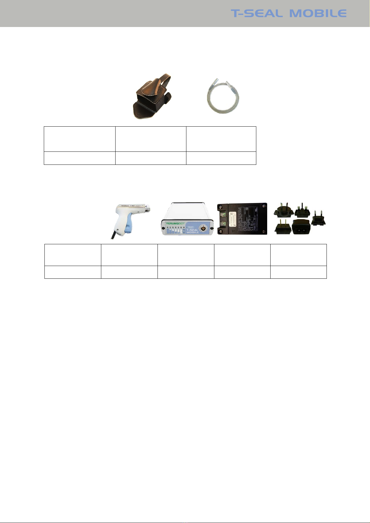
4.2 Parts
T-SEAL MOBILE comprises the parts listed below:
Description Hand unit Battery unit Battery charger
without plug
Kit Primary
Adaptors
Part No. 546900000 547900000 544900000 54410120
List of all cables and maximum lengths of cables, transducers and other electrical
accessories with which the manufacturer claims compliance (cables, accessories used
other than those listed may impact emission/immunity):
Part Reference Specification
Battery charger
without plug
8METSM003 Input: 100-240 V~/50-60 Hz/700 mA
Output: 18VDC/1.66A
Kit Primary Adaptors 8METSM037 Euro mains connector
UK mains connector
Australia mains connector
USA/Japan mains connector
IEC 320 mains connector
9
SPECIFICATIONS, PARTS AND ACCESSORIES
4.3 Accessories
Description Holster Extension cord
1.2 m 5-pol
REF 8METSM004 8METSM005
4.4 User Interchangeable Parts
Description Hand unit Battery unit Battery charger
without plug
Kit Primary
Adaptors
REF 8METSM001 8METSM002 8METSM003 8METSM037

10
INSTALLATION
5INSTALLATION
This chapter involves unpacking, temperature requirements and installation of the
instrument.
5.1 Unpacking and Inspection
1. Visually inspect the cardboard box for damage. Report any damage immediately.
2. Lift the instrument out of the cardboard box and place it on a flat surface.
The instrument is shipped in one cardboard box that includes:
I. 1 Hand unit
II. 1 Battery unit
III. 1 Battery charger without plug
IV. 1 IFU (English)
V. 1 Kit Primary Adaptors
3. The above list is subject to change, refer to the packing list for accurate description of
contents. If any parts are missing or if the parts are damaged, report it immediately.
4. Please keep all shipping and packaging materials, as they may be required for later
transportation, at least during the warranty time.
5.2 Environmental Requirements
To keep the instrument operating at its best, please observe the following:
•The instrument should be placed on a flat surface free from dust, solvents and acidic
vapor.
•Use the instrument in an area free from vibration and with a room temperature of 15 -
35°C (60 - 95°F), and relative humidity 10% - 90%.
•Handle the components with care in a clean environment.
11
INSTALLATION
5.3 Installation Procedure
Preparing the sealer for use
1. Fit correct mains input plug to the Battery charger.
2. The changeable mains connector is available for European continent (standard), UK,
USA/Canada and Australia/New Zealand and as IEC standard 320 C8.
3. Connect the charger (grey on connector) to the combined Hand unit/Battery charger
cable connector.
4. Plug the charger into the mains. The charger can be connected to mains voltages
between 100 and 240 V AC.
5. It takes about three hours to charge the Battery unit completely. When the charging
level indication on the unit indicates 100% and the recharge indication flashes, the
battery is fully charged.
6. Charge the battery to 100% before the first use.
7. Connect the Hand unit cable (grey at end of the cable) into the Battery unit connector.
Make sure the connector snaps in secured position.
8. Perform a test seal on an empty or water filled tube to ensure proper operation.
CAUTION Only use the enclosed Battery charger for charging the Battery unit.
NOTE Ensure that cable to handle is connected before use.

12
FUNCTIONAL DESCRIPTION
6FUNCTIONAL DESCRIPTION
This chapter describes how T-SEAL MOBILE works, where the connectors and the
indications are placed on the unit and their functions.
Front view of Battery unit
Charge level
indicator
Recharge
indicator
Battery test
button
Hand unit/Battery
charger cable
connector
Rear view of Battery unit
View of Hand unit
Seal indicator
Tube slot
Spring lock
Trigger
Electrode remove grip

13
FUNCTIONAL DESCRIPTION
View of Charger
6.1 Description of Sealing
The tube to be sealed is placed in the slot of the Hand unit, between the electrodes. When
the user presses the trigger on the Hand unit, the tube is pressed together and the sealing
procedure will commence automatically. The radio frequency (RF) generator starts and the
energy is transferred from the fixed electrode to the tube, which melts to a sterilized welding
pattern.
During the whole sealing process the orange Seal light on the front of the Hand unit is lit.
When this light goes out, the sealing is complete and the trigger may be released. The
intelligent sense control in the Hand unit detects, controls, and adjusts the necessary sealing
activity to give the best sealing quality for the type of tubes that are being used.
See section 7.4 for a description of the different LED indications on the Hand unit in case of
problems.
6.2 Description of Equipment
T-SEAL MOBILE consists of a Battery unit and a Hand unit. Below is a short description of
each component.
The Hand unit consists of an RF-generator with intelligent sense control, ergonomic handgrip
with trigger, the moving electrode (which can be removed for cleaning) and the cable with
connector. The Hand unit takes no power between sealing.
The Battery unit consists of the environmental friendly LiIonMn battery pack, built-in optic
charge level indicator and the combined charger/handle connector. The charge in the
Battery unit is sufficient for approximately 1500 seals.
Power indicator

14
FUNCTIONAL DESCRIPTION
6.3 Checking the Battery unit
To check the battery, just press the “TEST” button ❸and the battery charge level indicator
❶lights up. The capacity indication is in steps of twenty percent. The battery can be
recharged at any time or at least when zero (red) remains. The zero level is also indicated on
the handle with the red light and when seal is attempted, the seal function will be blocked.
Recharging the battery:
Connect the Battery charger to the Battery unit ❹and the charger to the mains. The
recharge indicator ❷lights up.
When the recharge indicator starts flashing, the battery is fully charged and the charge
current is automatically turned off. The charge can be interrupted at any time without
damage to the cells, but a full recharge will take less than three hours and is recommended.
❶❷❸❹
CAUTIONS Always check the seals when the battery capacity is low (20% or
less). See section 7.2 for sealing pattern.
Only use the enclosed Battery charger for charging battery in the
Battery unit.
NOTES To guarantee a long lifetime for the rechargeable battery, please
observe the following requirements: Charge the battery at
temperature between 5 and 35°C (40-95°F).
If the indicator ❷does not light up, check the connection to the
charger and mains.

15
OPERATING INSTRUCTIONS
7OPERATING INSTRUCTIONS
This chapter describes the use of the instrument.
WARNINGS T-SEAL MOBILE uses radio frequency (RF) energy to generate heat
for sealing. Users should be cautious of potential electrical shocks or
hazards while handling this sealer. Always keep your fingers away
from the electrodes in the slot. Never place any object other than the
tube between the electrodes.
This machine emits a low level of electromagnetic (non-ionizing)
radiation while sealing. It should not be used near high frequency
sensitive electronic equipment.
See table 1 for guidance.
Do not allow the Hand unit to come directly in contact with the donor.
Do not perform a seal within 8 cm (3 in) of needle to preclude an RF
burn at the needle entry point.
CAUTIONS Inspect all parts of the instrument for defects before use. Check
sealing pattern if Hand unit is dropped.
Always check the seals when the battery capacity is low (20% or
less).
7.1 Preparation before Use
1. Place the instrument on a flat surface near the working place or in the holster.
2. Check that there is sufficient battery capacity by pushing the “TEST” button.
3. Connect the Hand unit cable into the combined Hand unit/Battery charger cable
connector.
NOTE Do not try to connect other sealers to the T-SEAL MOBILE Battery
unit than the Terumo BCT T-SEAL MOBILE Hand unit.
7.2 How to Seal Tubes
1Put the tube to be sealed down to the bottom of the slot in the Hand unit.
2Check that the tube is placed between the electrodes in the slot.
3Press the trigger to bring the two electrodes closer together until the light on top of the
Hand unit comes on. The sealing time is normally 0.4 to 0.9 seconds; after a
maximum of 3 seconds the RF is turned off.
4When the light goes out, sealing is finished. Release the trigger and remove the tubing.
5The center of the sealed pattern is very thin and pulling both sides will divide the tube
into two pieces.
6Check the tube for leakage.
CAUTION If you should make two or more seals, they should not be within 1 cm
(0.4 in) of each other, otherwise the resulting pressure in the tube
may cause microscopic cracks and holes in the seals.
16
OPERATING INSTRUCTIONS
CAUTIONS In case of sealer malfunction (intermittent operation, poor seal quality,
the sealing time seems too long or too short) contact your local
Terumo BCT representative for assistance.
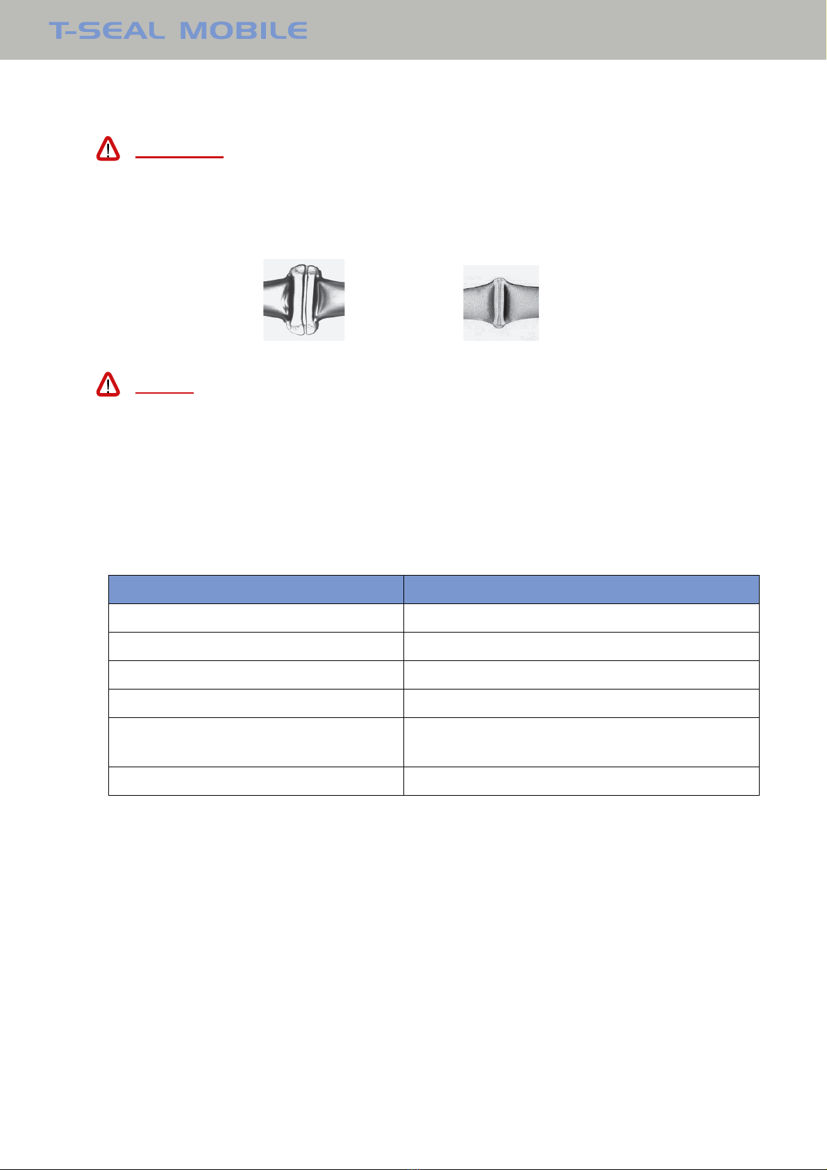
Periodically check whether the shape of the seal is symmetrical and
there is a clear line in the middle of the seal (see picture below).
Good sealing pattern Bad sealing pattern
NOTES The tube must be dry on the outside.
Do not pull the tube and keep the trigger fully pressed down until the
light goes out. If the trigger is released the sealing process stops.
7.3 If the Sealer Doesn´t Start
The Sealer has several safety functions. Before sealing, these functions control and identify
whether it is possible to seal the tube. The table below covers the common probable causes
for problems and suggests some recommended actions.
Probable cause Recommended action
Leaky or wet tube Dry the tube and try again
Tiny arcs between the electrodes Dry the electrodes and try again
Wet or dirty electrodes Clean and dry the electrodes
Low/no capacity in battery Check/charge battery
Overheated (Hand unit LED red blinking)
Let the Hand unit cool down.
No seals Check Battery unit and connection.
If the sealer still doesn’t start, see chapter 8 for further information
7.4 LED indications
Battery unit
•“Colored LEDs bar indicating battery status.”
•“TEST”: button to check the battery. When pressed, the battery charge level indicator
lights up. Refer to section 6.3.
Hand unit
•Indicator lights orange when RF-energy is being applied to the fixed electrode and
turns off when sealing is completed.
•Indicator flashes red at overheating, sealing function is blocked.
•Indicator lights red one second in case of short circuit, sealing function is blocked.
•Indicator lights red in case of battery low level, sealing function is blocked.

17
TROUBLESHOOTING
8TROUBLESHOOTING
Maintenance performed by the user is limited to changing Battery unit and Hand unit. The
following information covers common problems and offers suggested solutions.
8.1 Battery Unit
Problem Probable cause Recommended action
Charge level LEDs doesn’t
light.
Battery too low voltage. Charge battery for 3 hours.
Fuse blown. Contact your local Terumo BCT representative.
Other cause. Contact your local Terumo BCT representative.
Charge Level LEDs do not
light up during charge
No voltage Charge battery for 48 hours
Fuse blown. Contact your local Terumo BCT representative.
Other cause. Contact your local Terumo BCT representative.
Charge Level LEDs do not
light up after 48 hours
charge
Battery unit defective. Change battery unit or contact your local
Terumo BCT representative.
18
TROUBLESHOOTING
8.2 Hand Unit
Problem Probable cause Recommended action
The sealing doesn’t start. Wet electrodes. Dry the electrodes, see chapter 9.2.
Dirty electrodes. Clean the electrodes, see chapter 9.2.
Wet tube. Dry the tube and electrodes, try again.
Tiny arcs between the
electrodes.
Dry the electrodes and try again.
The trigger does not “click"
when it is fully squeezed.
Change Hand unit or contact your local Terumo
BCT representative.
The trigger cannot fully
engage when it is
squeezed
Hand unit defective.
Battery not charged/low
charge.
Charge battery for 3 hours.
Cable broken. Contact your local Terumo BCT representative.
Other cause.
Bad sealing. Low battery charge. Check the Battery unit charge level.
Charge battery if needed.
Moving electrode doesn’t
move smoothly in handle.
Clean and oil electrode shaft,
see chapter 9.2.
Wet electrodes. Dry the electrodes and try again.
Dirty electrodes. Clean the electrodes, see chapter 9.2.
Moving electrode out of
position.
See chapter 9.2, assembly of electrode.
Hand unit defective. Change Hand unit or
contact your local Terumo BCT representative.
Other cause. Contact your local Terumo BCT representative
Hard to divide tube after
seal.
Moving electrode doesn’t
move smoothly in handle.
Clean and oil electrode shaft, see chapter 9.2.
Wet electrodes. Dry the electrodes and try again.
Dirty electrodes. Clean the electrodes, see chapter 9.2.
Rim on moving electrode
damaged. Contact your local Terumo BCT representative.
Other cause.
Intermittent sealing. Hand unit defective. Change Hand unit or contact your local Terumo
BCT representative.
Cable broken. Contact your local Terumo BCT representative.
Battery unit defective
Hand unit LED still alight
after seal trigger has been
released.
Hand unit defective Change Hand unit or contact your local Terumo
BCT representative.
Hand unit LED doesn’t
light.
Hand unit defective Contact your local Terumo BCT representative.
Hand unit LED flickers. Cable broken Contact your local Terumo BCT representative.
Other cause
Electrode cannot be
inserted after cleaning
Trigger has been pressed
during cleaning which
means that internal spring
can come out of position.
The spring can be reset to its correct position by
pulling out the trigger to the outer locked
position. Thereafter carefully insert a pin (Ø3-
4mm, 100mm long) in the front hole where the
electrode is inserted and slightly push it
downwards. Be careful; do not scratch the
surface with the pin.

19
CLEANING
9CLEANING
This chapter gives information on the cleaning (procedure, frequency) of the Battery and
Hand units. The Sealer requires minimal maintenance for efficient operation. Follow the
cleaning procedure below.
WARNINGS For you own safety always disconnect the Hand unit or charger from
the Battery unit.
Blood and blood products must be treated as potentially infectious at
all times. In the event of blood spillages, appropriate protective
clothing should be worn during cleanup procedures.
After removing residual biological material, surfaces which have been in contact with blood or
components must be disinfected using a chemical agent considered to be “sterilizing”
(isopropyl Alcohol 70%,....). Alternatively, a freshly prepared sodium hypochlorite (household
bleach) solution may be used to disinfect surfaces. Diluted solutions of 1 part bleach to 10
parts water may be used.
Regardless of the “sterilant” or disinfection solution used, remember to remove any residue
to ensure that surfaces of the equipment are not subject to corrosion or discoloration.
Discard all materials in contact with blood according to institutional policies regarding disposal
of biohazardous materials.
CAUTIONS Do not disinfect or sterilize any part of the Sealer through autoclave,
or with ethylene oxide gas. To do so will render the Sealer unusable
and invalidate the warranty.
Do not use chemical or abrasive cleaners such as acetone, ammonia
or similar. Do not use sharp edged tools for cleaning, which could
damage the finish of the units.
Do not allow liquid to flow in the electronic part of the machine.
9.1 Battery unit
Cleaning may be required as a result of spilled drops of blood or once per month.
If spillage occurs, the unit must immediately be removed from service and cleaned
completely before resuming use.
Use a soft lint-free tissue, moistened with a mild detergent to clean the outside of the Battery
unit.
CAUTION Do not, under any circumstances, submerge the Battery unit in any
kind of liquid. This will damage the battery and void the warranty.
20
CLEANING
9.2 Hand Unit
Clean once per week or more frequently, as required, if spillage of blood occurs.
For cleaning the electrodes remove the moving electrode.
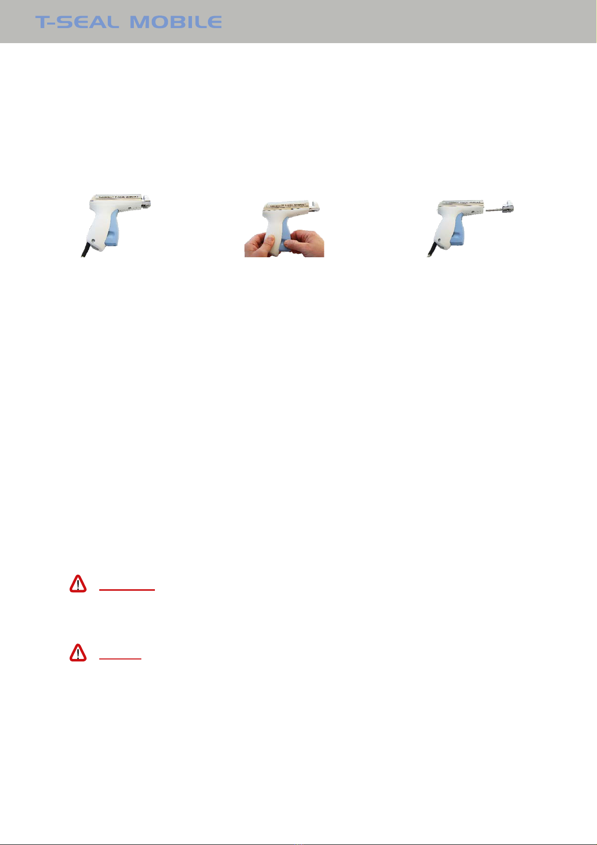
Removal of moving electrode:
1. Pull the blue trigger to “click” to release the moving electrode. Push spring lock
forward.
2. First push inward, then pull out the electrode.
Clean the handle and both electrodes with a soft lint free cloth moistened with mild
detergent. Dry carefully and ensure that the electrodes are completely dry to prevent sparks.
To clean the electrode shaft, use a dry cotton swab.
After cleaning, inspect the electrodes for any mechanical damage or wear out. Do not use
damaged part.
For proper function, add a drip of light machine oil on electrode shaft after each cleaning!
Assemble the parts in reverse order.
Make sure the trigger and spring lock is in full forward position before electrode insertion.
Insert the moving electrode ensuring that it is positioned so as to be parallel with the fixed
electrode. Press the trigger twice and ensure that the moving electrode moves smoothly, is
in position and not loose.
CAUTION The hand unit is not waterproof. Do not, under any circumstances,
submerge the hand unit in any kind of liquid. Doing so will generate
tiny electric discharges, cause the device to malfunction, and void the
warranty.
NOTES Some sealing tests are recommended before resuming use.
Compare the pattern against picture in section 7.2.
Do not push the trigger in after removing the electrode since this may
block the locking mechanism.
If electrode cannot be inserted after cleaning, the trigger is probably
pressed during cleaning. To insert the front electrode again, see
chapter 8.2.
This manual suits for next models
1
Table of contents


