TESSERA TK-78K0R/KG3+UD User manual

User’s Manual
TK-78K0R/KG3+UD
ZigBeeTM-ready
Wireless Network Evaluation Board
Using the UZ2400 RF chip
and the 78K0R/KG3 Microcontroller
Date published: October 2009
Rev. 3.0
© TESSERA TECHNOLOGY INC. 2009
Printed in Japan
- 1 -

Welcome to the world of TK-78K0R/KG3+UD.
You are now being navigated to the design environment
of the 78K0R microcontroller for developing wireless
network applications. Please follow the tutorial step by
step.
- 2 -

[NOTES]
The information in this document is subject to change without notice. No part of
this document may be copied or reproduced in any form or by any means without
the prior written consent of TESSERA TECHNOLOGY INC.
TESSERA TECHNOLOGY INC. assumes no liability for infringement of patents or
copyrights of third parties by or arising from use of a product described herein.
This product is designed and manufactured with intention for use in evaluation
and prototyping by engineers with knowledge of security, safety and reliability.
TESSERA TECHNOLOGY INC. would like to inform, that the standard quality
assurance procedure(s) have not been fully applied to this product and its
documentation and that TESSERA TECHNOLOGY INC. cannot assure the full
and error free function and/or the standard quality level.
[CAUTION]
This equipment should be handled like a CMOS semiconductor device. The user
must take all precautions to avoid build-up of static electricity while working with
this equipment. All test and measurement tool including the workbench must be
grounded. The user/operator must be grounded using the wrist strap. The
connectors and/or device pins should not be touched with bare hands.
- 3 -

Contents
1INTRODUCTION........................................................................................... 8
2PREPARATIONS........................................................................................ 10
2.1 Development Tools, Sample Programs, and the MAC Library.................................. 11
2.1.1 Integrated Development Environment PM + V6.31 .......................................................... 11
2.1.2 Device file DF781188 V3.00............................................................................................. 11
2.1.3 C Compiler CC78K0R W2.12 : Code size limited version................................................ 11
2.1.4 Assembler RA78K0R W1.33 : Code size limited version ................................................. 11
2.1.5 78K0R integrated debugger ID78K0R-QB V3.60............................................................. 11
2.1.6 78K0R Starter Kit Setting.................................................................................................. 11
2.1.7 Starter kit USB driver ........................................................................................................ 12
2.1.8 The RF Test Program....................................................................................................... 12
2.1.9 IEEE 802.15.4 MAC Library.............................................................................................. 12
2.1.10 The MAC Sample Program1 : Text Chat Program......................................................... 12
2.1.11 The MAC Sample Program2 : LED Control.................................................................... 13
2.2 Installation of Software Development Tools............................................................... 14
2.2.1 Start-up of the installation CD-ROM ................................................................................. 14
2.2.2 Installation of the software development tools.................................................................. 14
2.2.3 Uninstall ............................................................................................................................ 21
2.2.4 File Configuration in PC.................................................................................................... 22
2.3 USB Driver .................................................................................................................... 23
2.3.1 Install to Windows XP....................................................................................................... 24
2.3.2 Install to Windows2000..................................................................................................... 27
2.3.3 Confirmation of the installation ......................................................................................... 31
2.4 Sample Environment.................................................................................................... 32
2.4.1 Installation of the sample programs.................................................................................. 33
2.4.2 File Configuration of the sample program ........................................................................ 36
3EXPERIENCES........................................................................................... 37
3.1 Starting PM + ................................................................................................................ 39
3.2 Introduction to PM +..................................................................................................... 40
3.3 Loading Workspace (Project)...................................................................................... 42
3.4 Configuration of Linker Option.................................................................................... 44
- 4 -

3.4.1 "Output1" Tab ................................................................................................................... 44
3.4.2 "Output2" Tab ................................................................................................................... 46
3.5 Configuration of Compiler Option............................................................................... 47
3.5.1 "Extend" Tab..................................................................................................................... 47
3.5.2 "Startup Routine" Tab ....................................................................................................... 48
3.6 Configuration of Debugger setting ............................................................................. 49
3.7 TK board setting........................................................................................................... 51
3.8 Creating execution format ........................................................................................... 52
3.9 Starting integrated debugger (ID78K0R-QB).............................................................. 54
3.10 Introduction of the integrated debugger(ID78K0R-QB)............................................ 59
3.11 Executing a program.................................................................................................... 60
3.12 Stop a program............................................................................................................. 61
3.13 Terminating integrated debugger (ID78K0R-QB)....................................................... 62
3.14 The RF Test Program ................................................................................................... 63
3.14.1 Procedure for one to one transmit/receive test .............................................................. 63
3.14.2 PER test / receiver.......................................................................................................... 75
3.14.3 Continuous TX / Pseudo Noise ...................................................................................... 75
3.14.4 Continuous TX / Raw carrier .......................................................................................... 75
3.14.5 RX Mode......................................................................................................................... 75
3.14.6 IDLE MODE .................................................................................................................... 75
3.14.7 Standby MODE............................................................................................................... 75
3.14.8 Deep Sleep mode........................................................................................................... 76
3.14.9 Power down mode.......................................................................................................... 76
3.14.10 Set RF channel ............................................................................................................. 76
3.14.11 Manually set UZ2400 register....................................................................................... 76
3.14.12 Resetting RF................................................................................................................. 76
3.15 Terminating PM +.......................................................................................................... 77
4HARDWARE SPECIFICATIONS................................................................ 78
4.1 Layout of hardware functions...................................................................................... 79
4.2 Hardware Functions..................................................................................................... 80
4.2.1 SW1 .................................................................................................................................. 80
4.2.2 SW2 .................................................................................................................................. 82
4.2.3 SW3,SW4 ......................................................................................................................... 83
- 5 -

4.2.4 SW5 .................................................................................................................................. 83
4.2.5 JP1.................................................................................................................................... 84
4.2.6 LED1................................................................................................................................. 84
4.2.7 LED2, LED3 and LED4..................................................................................................... 84
4.2.8 FP1 ................................................................................................................................... 85
4.2.9 CON2 .................................................................................................................................. 85
4.2.10 U1 ..................................................................................................................................... 85
4.3 Universal Area .............................................................................................................. 85
4.4 Solder-short pad........................................................................................................... 85
4.5 Power supply................................................................................................................ 86
5THE IEEE 802.15.4 MAC SAMPLE PROGRAM........................................ 87
5.1 The MAC Sample program 1 :TextChat....................................................................... 88
5.1.1 Programming to the TK boards ........................................................................................ 89
5.1.2 Setting up the board to your PC ....................................................................................... 90
5.1.3 Designation of a coordinator............................................................................................. 92
5.1.4 Network Association ......................................................................................................... 92
5.1.5 Text Chat .......................................................................................................................... 93
5.2 The MAC Sample Program2 : LED Control................................................................. 95
5.2.1 Programming to the TK boards ........................................................................................ 96
5.2.2 Starting up a coordinator .................................................................................................. 96
5.2.3 Starting up end devices .................................................................................................... 98
5.2.4 Operation ........................................................................................................................ 100
6TROUBLESHOOTING.............................................................................. 101
6.1 If you cannot find USB driver when you connect PC to the kit............................... 101
6.2 Error when you start the debugger........................................................................... 101
6.2.1 "Can not communicate with Emulator..." (F0100 or A0109)........................................... 102
6.2.2 "Incorrect ID Code." (Ff603) ........................................................................................... 102
6.2.3 "The on-chip debug function had been disabled in the device." (F0c79) ....................... 102
6.2.4 "Disabling the on-chip debug function is prohibited." (F0c33)........................................ 103
7OTHER INFORMATION ........................................................................... 104
7.1 Create a new workspace............................................................................................ 105
7.2 Registration of new source files................................................................................ 110
7.3 Debugger tips ............................................................................................................. 112
- 6 -

7.3.1 Change display of buttons .............................................................................................. 112
7.3.2 Display source list and function list................................................................................. 112
7.3.3 Set/delete breakpoints.................................................................................................... 113
7.3.4 Display global variables.................................................................................................. 114
7.3.5 Display global variables while programs are running ..................................................... 115
7.3.6 Display local variables .................................................................................................... 116
7.3.7 Display memory and SFR contents ................................................................................ 116
7.4 Erase of flash memory............................................................................................... 117
7.5 BOM List & Circuit diagram....................................................................................... 119
8MODE SETTING OF THE BOARD........................................................... 125
- 7 -

1 Introduction
Target Reader Software development engineers who wish to become
familiar with the development environment of the 78K0R
microcontrollers. It is assumed that the readers have been
familiar with basics of microcontrollers, C and assembler
languages, and the WindowsTM operating system.
Purpose For readers to become familiar with the design environment
and the application examples of wireless networks.
Overview This manual consists of the following contents
Chapter 1 Introductions
→Overview of this manual
Chapter 2 Preparations
→Introduction of soft tools, and sample programs and installation
Chapter 3 Experiences
→Guide to the basic operations of PM + and the integrated
debugger using sample programs.
Chapter 4 Hardware Specifications
→Explain the hardware of TK-78K0R/KG3+UD
Chapter 5 IEEE 802.15.4 MAC Sample Programs
→Learn sample programs, which utilize the MAC library
Chapter 6 Troubleshooting
→Describe how to solve troubles you may face, such as errors when
starting the integrated debugger (ID78K0R-QB)
Chapter 7 Other Information
→Introduce other information, such as how to create a new
workspace (project) on integrated development environment (PM+),
how to register additional source file, and some useful tips of the
integrated debugger.
The circuit diagrams of demonstration kit are included in this
chapter.
- 8 -

Chapter 8 Mode Setting of the Board
→Explanation of switch setting.
Trademark Microsoft and Windows are either registered trademarks or
trademarks of Microsoft Corporation in the United States and/or
other countries.
Adobe and Acrobat are trademarks of Adobe Systems
Incorporated (Adobe System Incorporated).
Other company names and product names that appear in this
document are the registered trademarks or trademarks of their
respective companies.
- 9 -

2 Preparations
This chapter introduces the development environment and describes how to
install the sample programs. The sample program can be tested on this
hardware platform of the evaluation kit.
- 10 -

2.1 Development Tools, Sample Programs, and the MAC Library
This section outlines the development tools, sample programs and the MAC
library used in this tutorial.
2.1.1 Integrated Development Environment PM + V6.31
This is a project manager, where you work for editing the source code,
compiling it, and initiating the debugger. The project manager works on MS
Windows 2000 or XP.
2.1.2 Device file DF781188 V3.00
A device file contains an MCU specific information. It instructs the
development tools what kind of an MCU the tools shall work for.
2.1.3 C Compiler CC78K0R W2.12 : Code size limited version
This is a free compiler for the 78K0R microcontrollers. The object code size
is limited to 64 Kbytes. It works on MS Windows 2000 or XP.
2.1.4 Assembler RA78K0R W1.33 : Code size limited version
This is a free assembler for the 78K0R microcontrollers. The object code
size is limited to 64 Kbytes. It works on MS Windows 2000 or XP. The
RA78K0R Assembler Package contains Structured Assembler
Preprocessor, Assembler, Linker, Object Converter, Librarian, and List
Converter.
2.1.5 78K0R integrated debugger ID78K0R-QB V3.60
The Integrated Debugger ID78K0R-QB offers a debug environment on
your PC, where the MS Windows 2000 or XP runs, if the TK board is
connected to the PC with USB. The USB I/F accesses to the OCD, On
Chip Debug, interface on the microcontroller.
2.1.6 78K0R Starter Kit Setting
If you forget about the security ID or if you set “Does not erases data of
flash memory in case of failures in enabling on-chip debugging”, you can
erase the flash memory by using this starter kit.
- 11 -

2.1.7 Starter kit USB driver
This is a software driver for PC to access to the USB interface of the
TK-78K0R/KG3+UD board.
2.1.8 The RF Test Program
The RF Test Program is used in [chapter 3 Experiences].
The RF Test Program is provided in the form of the C source codes.
If you wish to tailor the RF Test Program to meet your specific needs, you
can edit the source code, re-compile it with debug build to generate a load
module file, then, start the debugger to load the tailored execution code on
to the microcontroller for further debugging on the project manager PM +.
Alternatively, if debugging is not required, you can make a release build to
achieve a new hex file, on the project manager PM +.
As a general remark, please respect your local regulation of
electro-magnetic emission. In general, it is suggested to use the
TK-78K0R/KG3+UD board in a radio anechoic chamber.
2.1.9 IEEE 802.15.4 MAC Library
The IEEE 802.15.4 MAC Library offers an executable object-code library of
the MAC stack specified in the IEEE 802.15.4. Please refer to the MAC
Library manual for further details.
2.1.10 The MAC Sample Program1 : Text Chat Program
The MAC Sample program 1 is developed to provide with a simple
example to construct a star network utilizing the IEEE 802.15.4 PHY/MAC
standard.
The MAC Sample Program 1 offers,
1). Designation of a network coordinator in a star configuration
2). Text chat between a coordinator and an end device
To use the MAC Sample Program 1, you need to prepare at least two PC
with a USB interface and two TK-78K0R/KG3+UD boards.
The MAC Sample Program 1 is provided in the form of the C source
codes.
If you wish to tailor the sample program to meet your specific needs, you
can edit the source code, re-compile it with debug build to generate a load
module file, then, start the debugger to load the tailored execution code on
to the microcontroller for further debugging on the project manager PM +.
- 12 -

However, because the USB connection to instruct operation to the program
is occupied for the debugging purpose,
alternatively, you can make a release build to achieve a new hex file, on
the project manager PM +.
As a general remark, please respect your local regulation of
electro-magnetic emission. In general, it is suggested to use the
TK-78K0R/KG3+UD board in a radio anechoic chamber.
2.1.11 The MAC Sample Program2 : LED Control
The MAC Sample program 2 is developed to provide with another simple
example to construct a star network utilizing the IEEE 802.15.4 PHY/MAC
standard.
The MAC Sample Program 2 offers,
1). Designation of a network coordinator in a star configuration
2). LEDs on the coordinator board indicate which switch on which end
device is pressed.
To use the MAC Sample Program 2, you need to prepare one PC with a
USB interface and two TK-78K0R/KG3+UD boards or more boards, up to
5.
The MAC Sample Program 2 is provided in the form of the C source codes.
If you wish to tailor the sample program to meet your specific needs, you
can edit the source code, re-compile it with debug build to generate a load
module file, then, start the debugger to load the tailored execution code on
to the microcontroller for further debugging on the project manager PM +.
However, because the USB connection is occupied for the debugging
interface, the USB connection is not available for applications. Alternatively,
you may make a release build to achieve a new hex file, on the project
manager PM +.
As a general remark, please respect your local regulation of
electro-magnetic emission. In general, it is suggested to use the
TK-78K0R/KG3+UD board in a radio anechoic chamber.
- 13 -

2.2 Installation of Software Development Tools
2.2.1 Start-up of the installation CD-ROM
The attached CD-ROM contains Development Tools, documents and sample
soft ware.
You can install it using an installer.
2.2.2 Installation of the software development tools.
Please insert the CD-ROM in the drive. The installer will show up automatically.
If it does not start automatically, please initiate it by double clicking the
SETUP.EXE.
<1> Readme First
The contents of the CD-ROM, and some notes are available.
Please read it at first.
<2> Install…
Click “Install” to start installation of development tools.
For details, please refer to the next section.
- 14 -

<3> Documents
Manuals of development tools and the evaluation kit are available in PDF
files.
When this button is clicked, the WWW browser will start. Adobe® Acrobat®
Reader is available in the CD-ROM.
<4> Sample Program
Click this button to start the WWW browser for the sample program and the
tutorial.
<5> Link to NEC Electronics Microcontrollers
Click this button to start the WWW browser display the link to the NEC
Electronics Microcontroller web site
(http://www.necel.com/micro/index_e.html)
The NEC Electronics Microcontroller web page provides with the latest
product/tool information and FAQs.
<6> Exit
Terminate the setup.
- 15 -
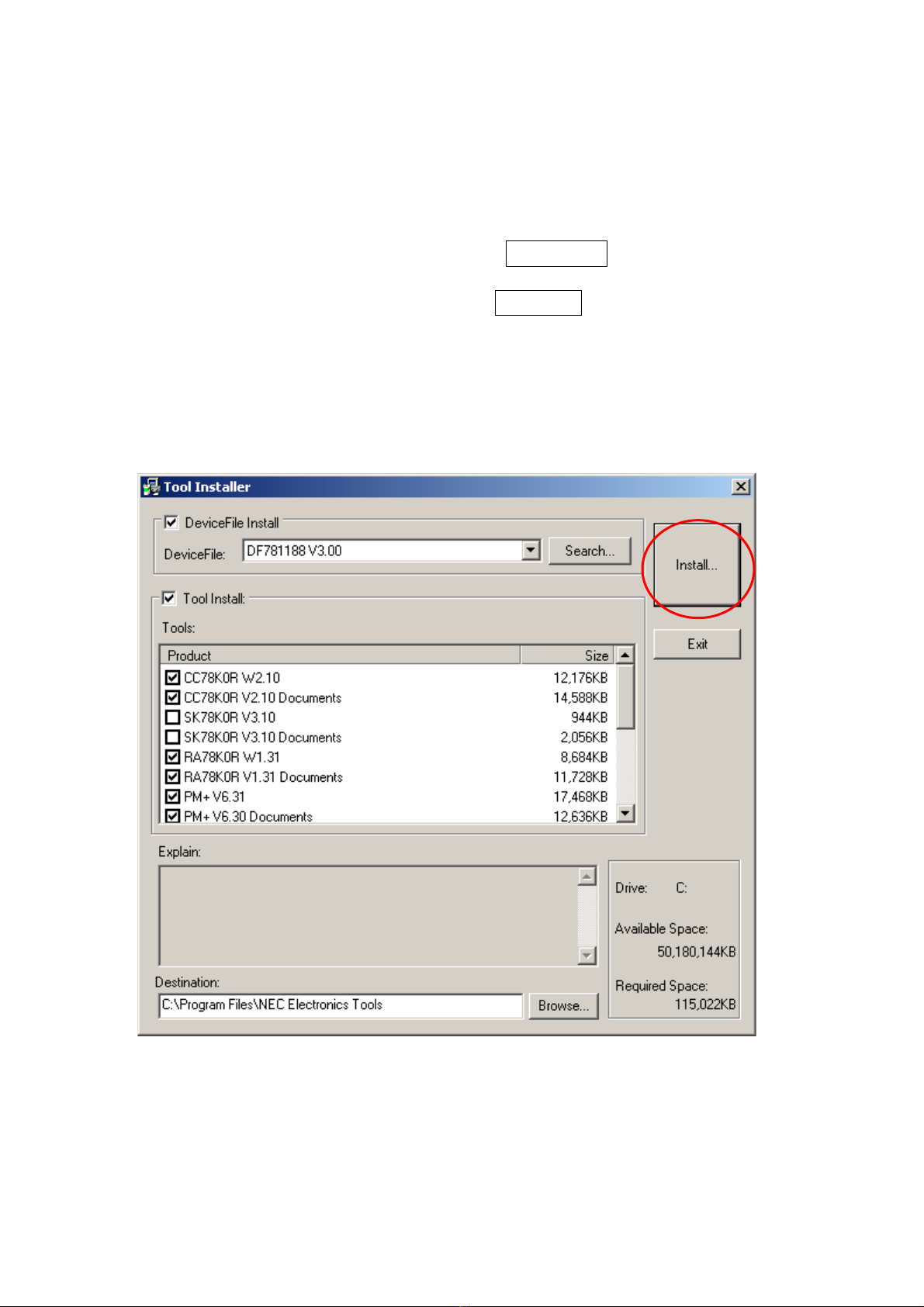
① Select products that you need to install.
(as default, all the products that you need to use the demostration kit
are selected.)
"Explain" area displays an explanation of the selected product.
To change the installation destination, click Browse….
When all the settings are completed, click Install….
* In this document, it is assumed that users install the programs under "NEC
Electronics Tools" directory (default installation directory). Users can find the
tools by selecting “Start Menu” -> "Programs" -> "NEC Electronics Tools".
- 16 -
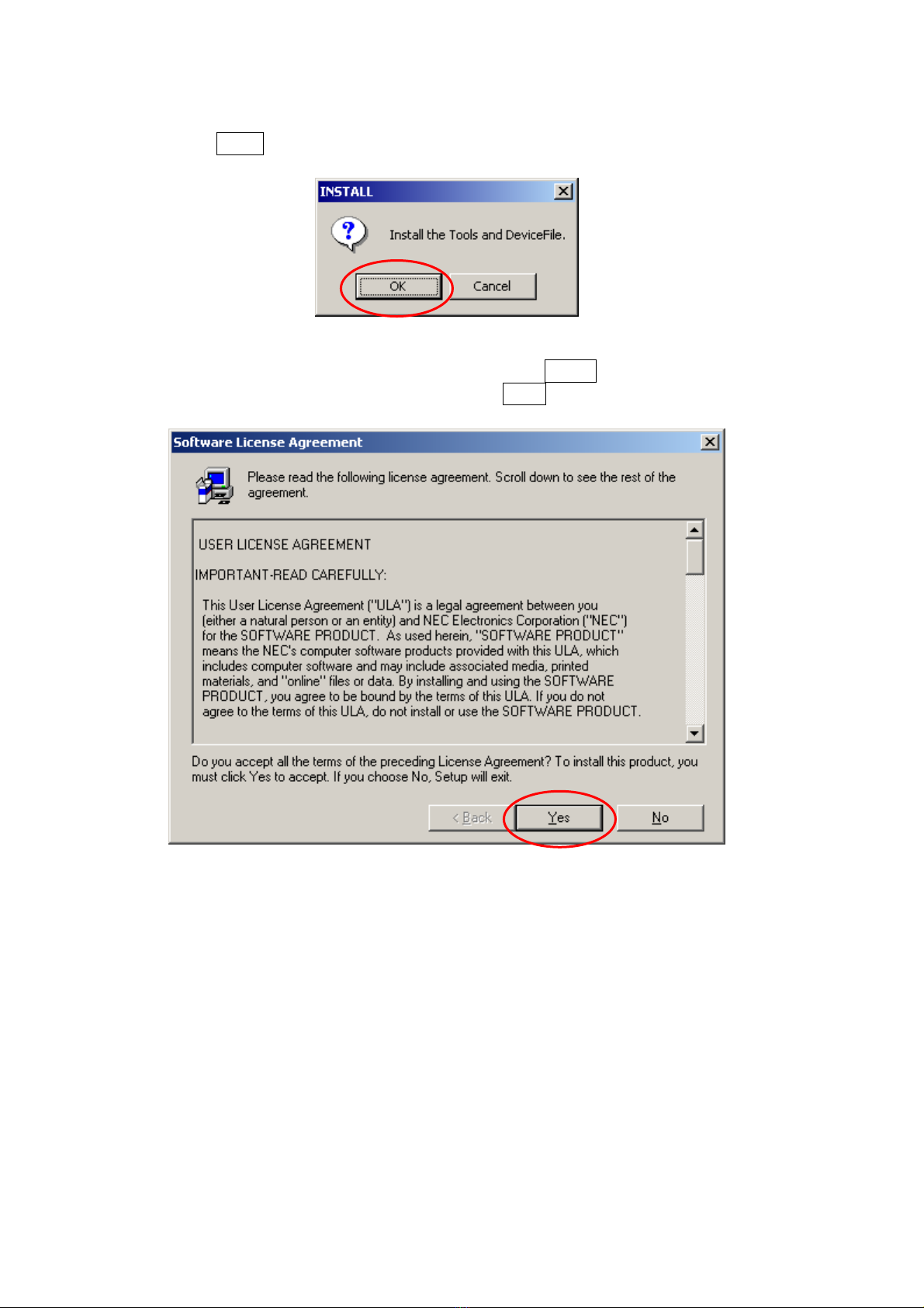
② Click OK when "Install" comfirmation dialog box is opened.
③ Read "software license agreement" and click Yes for continuing the
installation.To stop the installation, click No .
- 17 -
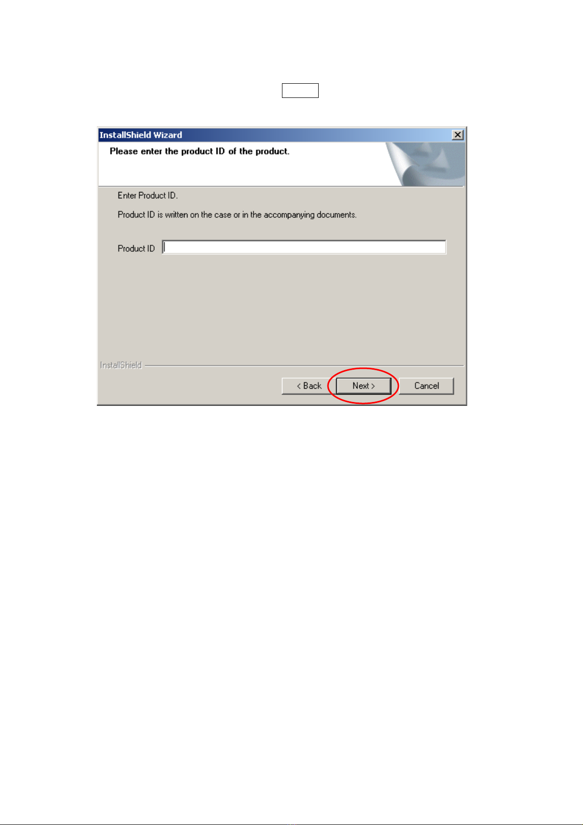
④ Enter the product ID, and click Next .
* The product ID is available on the “README.html” the other sheet.
⑤ It starts copying the files.
- 18 -
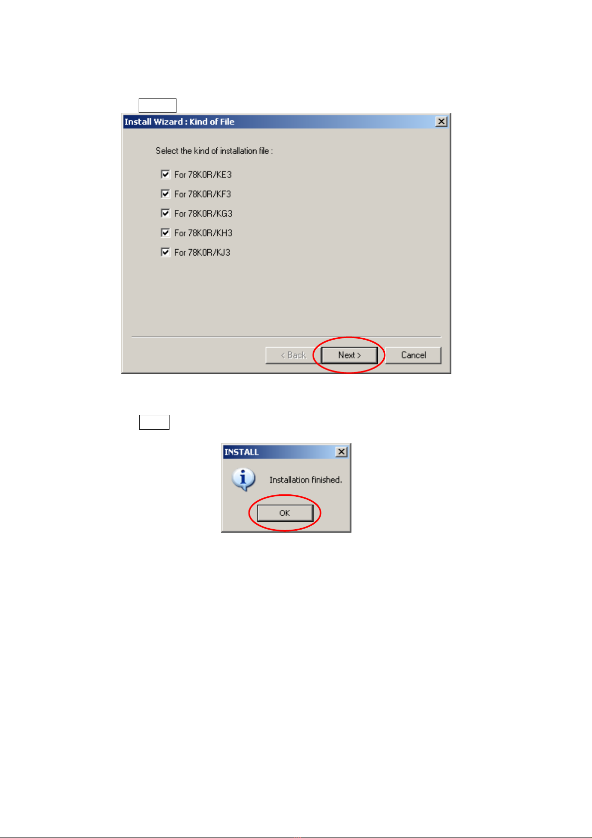
⑥ Click Next when "Select Files" installation wizard dialog opened.
⑦ When the installation is completed, the following dialog opens.
Click OK .
⑧ "NEC Electronics Starter Kit Virtual UART" USB driver must be installed on
PC before you connect to TK-78K0R/KG3+UD. Install the USB driver by
referring "2.3USB Driver".
- 19 -

Notes on the installation authority
To install this tool in Windows 2000 or XP, the authority of a administrator is
necessary. Therefore, please login as an administrator.
Notes on the install-directory
Please do not use 2-byte characters, such as umlaut in the directory name,
where the product is to be installed.
Note on the version of Windows
If the language of the Windows is not English, a file transfer error during
installation might be observed. In this case, please abort the installation in
the language, and re-install it in an English version of Windows.
The identical problem may be observed, if a language other than English is
specified as the system language in the “Regional Settings Properties” tab.
- 20 -
Table of contents
Other TESSERA Motherboard manuals


