Test Equipment Depot Skutch CK-2 User manual

Page 1 of 5
"Telecommunication Products to solve Telecommunication Problems"
CK-2
Promotion-On-Hold Module
(For GE 29487GE2 and 29488GE2)
Introduction
Thank you for purchasing
the Skutch CK-2 Promotion-
On-Hold Module for the
GE 29487 and 29488 four
line telephones. The CK-2
supplies Promotion-On-
Hold whenever any call is
placed ON HOLD with the
telephone's hold button. The
CK-2 not only supplies
Promotion-On-Hold, but it
also removes the annoying
"BEEPS" that these
telephones produce every 3
seconds when the phone is
placed on hold. The CK-2
will supply Promotion-On-Hold to callers that are placed ON HOLD ONLY from the
GE 2-9487 or 2-9488 telephones. Other makes and/or models of telephones can be used
with the CK-2 but they will not produce Promotion-On-Hold when placed ON HOLD.
Installation
There are two methods that can be used to install the CK-2 module. It basically depends
on how close the telephones are together. If all of the telephones are within 25 feet of a
central point, then method #1 can be used. In this case modular cords MUST be run
directly from the CK-2 box to each of the telephones. If your telephones are spread out
more than 25 feet apart, then you will need to use method #2. In this case you will have
to have a qualified person install four telephone jacks in front of your all of your
telephones. The CK-2 will have to be connected to these jacks. In this case the wiring to
the telephones remain unchanged. See method #2 for more details.
Modular Cords Power Cube
Audio Cord
99 Washington Street
Melrose, MA 02176
Fax 781-665-0780
TestEquipmentDepot.com

Page 2 of 5
Method #1 Installation:
This method should only be used when all phones are within close proximity of each
other. Up to five telephones can be connected with this method. It is okay to use
telephone extension cables if needed.
1- Disconnect all of your telephones.
2- Using a supplied telephone cord, connect one end to a wall telephone jack, Lines 1&2.
Connect the other end of the cord to the CK-2- "To Phone Lines", "Lines 1&2".
3- Using a supplied telephone cord, connect one end to a wall telephone jack, Lines 3&4.
Connect the other end of the cord to the CK-2- "To Phone Lines", "Lines 3&4".
4- Connect a telephone cord from each line 1&2 jack on each telephone, to a CK-2 jack
that is labeled "Phone 1&2". Order does not matter.
Telephone Jacks
1&2
1&2
1&2
1&2
1&2
3&4
3&4
3&4
3&4
3&4
Method #1
Test Equipment Depot - 800.517.8431 - 99 Washington Street Melrose, MA 02176
FAX 781.665.0780 - TestEquipmentDepot.com
Test Equipment Depot - 800.517.8431 - 99 Washington Street Melrose, MA 02176
FAX 781.665.0780 - TestEquipmentDepot.com

Page 3 of 5
5- Connect a telephone cord from each line 3&4 jack on each telephone, a CK-2 jack that
is labeled "Phone 3 & 4". Order does not matter.
6- Connect a audio cable from your audio source to the Audio In jack on the CK-2. Use
the audio cable supplied with the CK-2 ONLY if your audio source is a CD player. If you
are using a digital player, the digital player should have come with the needed audio
cable.
7- Connect the CK-2 and all telephone's power cubes to power.
Method #2 Installation:
This method should be used when your phones are spread out over a wide area It
requires that 4 telephone jacks be installed by a qualified person, in-between ALL
PHONES, and the telephone company. The DEMARCATION POINT is one place that
these jacks could be installed. The following diagram shows the relative location of these
jacks:
The following is a wiring diagram of how the jacks are to be installed:
Telephone Pole
De arcation Point
Office
Install Jacks within
this area
Test Equipment Depot - 800.517.8431 - 99 Washington Street Melrose, MA 02176
FAX 781.665.0780 - TestEquipmentDepot.com

Page 4 of 5
Red = Line #1 Ring GREEN CORDS are for Testing ONLY!
Green = Line #1 Tip They are removed before installing the CK-2.
Black = Line #2 Ring
Yellow = Line #2 Tip
1- When the jacks have been installed, without the modular cables attached as shown
above by the GREEN lines, all lines, on all phones should be dead. Check this before
continuing. If any of the phones get dial tone, the wiring is wrong. Fix this before
continuing.
2- Now attach the two modular cords (shown in GREEN), between the jacks, as shown
above. All lines should be working on all phones. If any lines are not working, the wiring
is wrong. Fix this before continuing!
3- Remove the two modular cords that are shown in GREEN.
4. Connect Jack Ato any one of the five CK-2 jacks labeled "Phone 1 & 2".
5. Connect Jack Bto "any one of the five CK-2 jacks labeled "Phone 3 & 4".
6. Connect Jack Cto "To Phone Lines" "Lines 1 & 2"
7. Connect Jack Dto "To Phone Lines" "Lines 3 & 4"
8- Connect the audio cable from your audio source to the "Audio In" jack on the CK-2. If
the audio source is a CD player, use the supplied audio cable with the CK-2. If your
source is a digital player, use the audio cable that came with it.
9- Connect Power Cube from CK-2 to power.
To Telephone Lines
To ALL Telephones
Lines
1&2
Lines
3&4
Lines
3&4
Lines
1&2
Modular Phone Cords
CO Side
Phone Side
A
B
C
D
Test Equipment Depot - 800.517.8431 - 99 Washington Street Melrose, MA 02176
FAX 781.665.0780 - TestEquipmentDepot.com

Page 5 of 5
Operation:
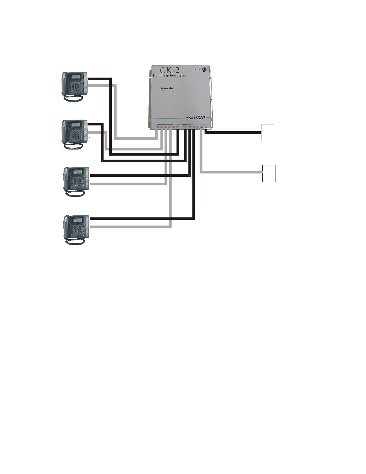
Operation is simple. When you place a caller ON HOLD from any of the GE 29487GE2
or 29488GE2 phones, the corresponding "Lines On Hold" light on the CK-2 will light
and the Promotion-On-Hold audio will be supplied to the ON HOLD caller. When the
line is re-answered, the Promotional audio will turn OFF and the call is re-connected to
the phone.
NOTE: When answering an ON HOLD call, the user must speak into the phone to reset
the CK-2. A "Hello" response is more than adequate.
• ONE YEAR LIMITED WARRANTY
This SKUTCH PRODUCT is warranted against defects for a period of one (1) year from the date of the
original invoice. Within this period, we will repair it without charge for parts and labor. To obtain
warranty service the product must be returned, at the customer's expense, to SKUTCH Electronics along
with a copy of the original invoice. After the unit has been repaired, SKUTCH will ship the PRODUCT
back via UPS GROUND service at our expense. If any other form of return shipment is requested, the
customer will pay for 100% of the shipping cost.
This Warranty does not apply if in the sole opinion of SKUTCH Electronics, the PRODUCT has been
damaged by lightning or any other Acts of God, or by accident, misuse, neglect, or improper packing,
shipping, modification or servicing by other than an authorized SKUTCH Service Center.
EXCEPT AS SPECIFICALLY PROVIDED IN THIS AGREEMENT, THERE ARE NO OTHER
WARRANTIES, EXPRESSED OR IMPLIED, INCLUDING, BUT NOT LIMITED TO, ANY IMPLIED
WARRANTIES OR MERCHANTABILITIES OR FITNESS FOR A PARTICULAR PURPOSE AND IN
NO EVENT SHALL SKUTCH ELECTRONICS BE LIABLE FOR LOSS OF PROFITS OR BENEFITS,
INDIRECT, SPECIAL, CONSEQUENTIAL OR OTHER SIMILAR DAMAGES ARISING OUT OF
ANY BREACH OF THIS WARRANTY OR OTHERWISE.
Test Equipment Depot - 800.517.8431 - 99 Washington Street Melrose, MA 02176
FAX 781.665.0780 - TestEquipmentDepot.com
Table of contents
Popular Control Unit manuals by other brands

System Sensor
System Sensor MDL3 Series Installation and maintenance instructions

MG
MG R7K4FML-6-DC32B instruction manual

Linear Technology
Linear Technology DC1872A manual

National Instruments
National Instruments NI PXI-2585 installation guide

MFB
MFB DRUM-07 operating manual

M-system
M-system R7M-SV4-R instruction manual

SMC Networks
SMC Networks VQC2000 Installation and maintenance manual

Kemper
Kemper KTS ComLog module operating instructions

Bandini Industrie
Bandini Industrie G:B:D: BA24 Instructions for installations

Cumberland
Cumberland Flex-Flo FLX-5350 Operation manual

Danfoss
Danfoss VMV 15 installation guide

Val-Matic
Val-Matic Swing-Flex Check Valve Operation, maintenance and installation manual