Test Products International Vib Meter 9085 User manual

© TPI Europe 2021 1 TPI 9085 User Guide V1.0
Vib Meter 9085
User Guide: Version 1.0
Vibration Monitoring & Analysis
Test Products International
9615 SW Allen Blvd Suite 104
Beaverton, OR 97005 USA
Tel: (800) 368-5719 Fax: (503) 520-1225
Web site: www.testproductsintl.com

© TPI Europe 2021 2 TPI 9085 User Guide V1.0
CONTENTS
CONTENTS.............................................................................2
DISCLAIMER..........................................................................2
1 OVERVIEW..........................................................................3
1.1 Special Requirement for Temperature Measurement...............................................................3
1.2 Turning the unit ON and OFF.....................................................................................................3
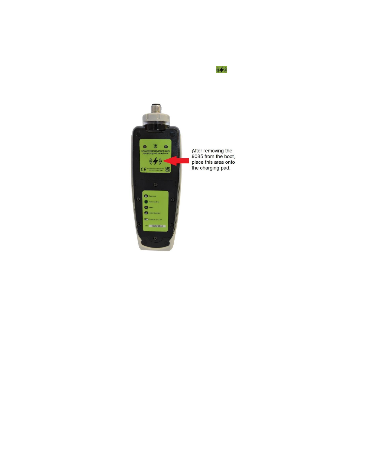
1.3 Batteries.........................................................................................................................................4
1.4 Service............................................................................................................................................4
2 OPERATION........................................................................5
2.1 Fitting the sensor...........................................................................................................................5
2.2 Taking a reading...........................................................................................................................5
2.2.1 Vibration & Temperature readings.........................................................................................6
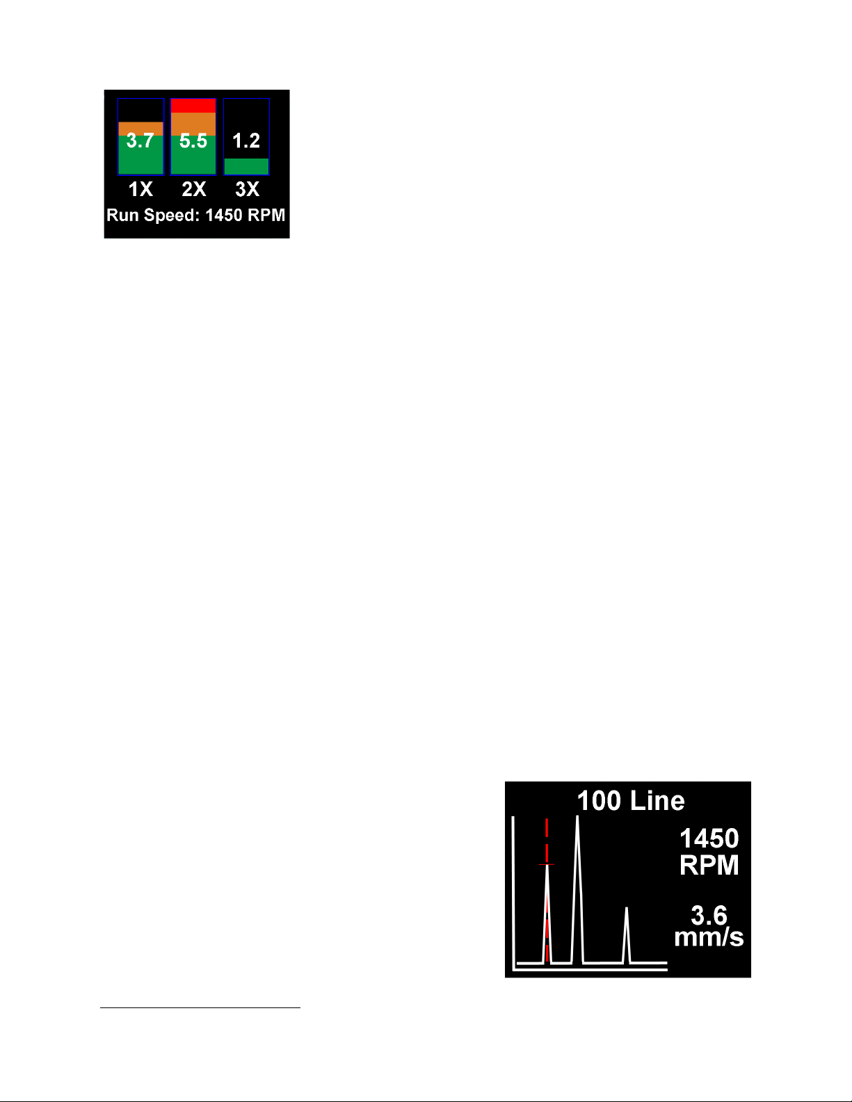
2.2.2 Vibration Analysis .....................................................................................................................7
2.2.3 Frequency spectrum ..................................................................................................................8
2.2.4 Live Update Mode......................................................................................................................9
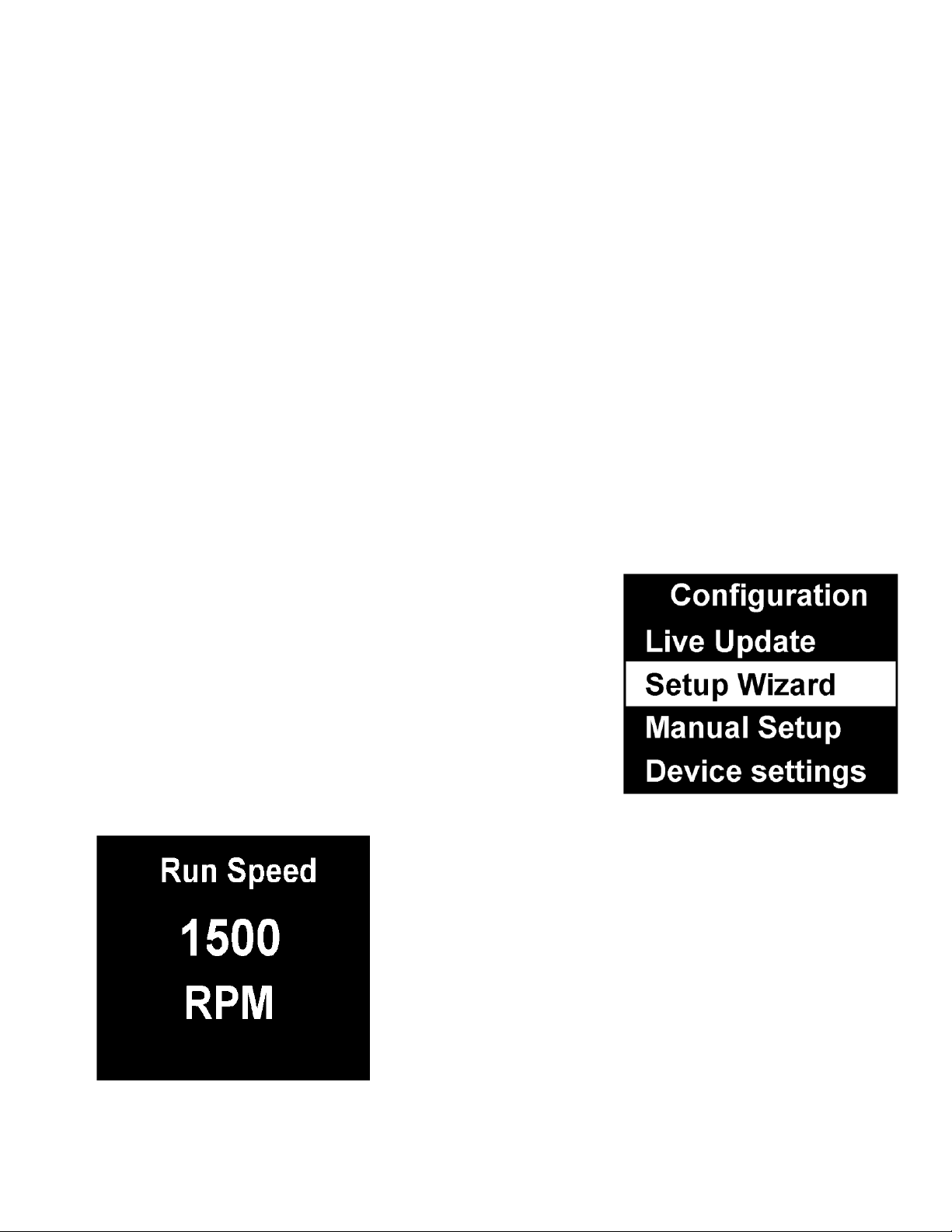
2.3 Configuration menus....................................................................................................................9
2.3.1 Setup Wizard..............................................................................................................................9
2.3.2 Manual Setup...........................................................................................................................10
2.3.2.1 BDU alarm settings...............................................................................................................10
2.3.3.2 Run Speed..............................................................................................................................11
2.3.3.3 Sensor mV/g ..........................................................................................................................11
2.3.4 Device Settings .........................................................................................................................11
3 ASSET MANAGEMENT ....................................................13
4 C-TREND II - TRENDING SOFTWARE.............................14
5 SPECIFICATIONS .............................................................15
6 BASIC OPERATION..........................................................16
Disclaimer
This document has been carefully prepared and checked. No responsibility can be assumed for inaccuracies.
TPI Europe reserves the right to make changes without prior notice to any products herein to improve
functionality, reliability or other design aspects. TPI Europe does not assume any liability out of the use of
any product described herein; neither does it convey any licence under its patent rights nor the rightsof others.
TPI Europe products are not authorised for use as components in life support services or systems. TPI Europe
should be informed of any such intended use to determine suitability of the products.
Copyright © 2021 TPI Europe Ltd.

© TPI Europe 2021 3 TPI 9085 User Guide V1.0
1 OVERVIEW
The Vib Meter 9085 is a simple to use vibration monitoring and analysis tool that allows
easy display of vibration signals. The meter automatically performs vibration analysis
functions based on machine running speed to help diagnose faults such as unbalance,
misalignment and looseness, as well as indicating the degree of bearing wear.
The Vib Meter 9085 unit is designed to enable a user to collect vibration and
temperature measurements from assets (e.g. pumps, motors, fans and bearings). The
unit displays vibration frequency plots and allows vibration severity and bearing
condition to be monitored, analysed and trended with the included VibTrend PC
analysis software.
1.1 Special Requirement for Temperature Measurements
To measure temperature with the 9085 the accelerometer with built in temperature
sensor (p/n A9101) must be used. This is a low power accelerometer with temperature
sensor and built-in magnet. Using the standard low power accelerometer (p/n A9100)
will allow the 9085 to measure vibration but not temperature.
1.2 Turning the unit ON and OFF
Turning the meter ON is achieved simply by pressing the center or button. The
unit has an auto dimming feature that dims the display after 10 seconds to conserve
battery life. Pressing any button will bring the unit back to full brightness. In addition, the
9085 will automatically turn OFF if not used for 1 minute (this time period can be
increased up to 60 minutes using the Setup Wizard).

© TPI Europe 2021 4 TPI 9085 User Guide V1.0
1.3 Batteries
The Vib Meter 9085 is powered by a wireless rechargeable Lithium-Ion battery. To
charge the battery, remove the 9085 from the protective boot by prying the boot off from
the bottom. Set the 9085 on the charging pad so the symbol comes in contact
with the pad. The display of the 9085 will turn on to indicate it is charging.
1.4 Service
The Vib Meter 9085 contains no user serviceable parts. In the unlikely case of
malfunction please return the complete unit to your supplier for repair.

© TPI Europe 2021 5 TPI 9085 User Guide V1.0
2 Operation
2.1 Fitting the sensor
The Vib Meter 9085 is supplied with a cable connected accelerometer (sensor) that
connects to the 5 pin M12 connector on the meter. The nominal sensitivity of the sensor
is 30mV/g and this is the meter’s default setting for sensor sensitivity.
The Vib Meter 9085 can accept the A9100 standard low power accelerometer or the
A9101 low power accelerometer with temperature sensor. The sensor sensitivity setting
of the 9085 can be adjusted to accommodate different accelerometer sensitivities (see
section 2.3.3.3 in Manual Setup).
2.2 Taking a reading
To take a reading, press the circle button to turn the unit ON. Place the sensor on
a rigid part of the machine as close as possible to the desired measurement point (e.g.
bearing block) using the magnet mount.
Pressing the circle button again takes the
reading.
N.B. for best results the sensor should
be placed gently onto the
measurement point by “rolling” the
magnet onto the machine.
This is in order to avoid any sudden
shocks that would be seen as large
acceleration peaks by the sensor and
could take some time (several
seconds) to die away.
Taking a reading causes the overall vibration numbers
and temperatrue screen to be displayed as shown in the
example screen left. Note: Temperature will not display
if a standard low power accelerometer without
temperature (p/n A9100) is used.
This screen gives an overall view of the machine’s
vibration condition as explained in the following section.

© TPI Europe 2021 6 TPI 9085 User Guide V1.0
2.2.1 Vibration & Temperature readings
Once a vibration reading has been taken, the display will show four values, as shown in
the example screen opposite. The values are colour coded to show their alarm status as
explained in the following sections.
The four values shown in the readings screen are:
•ISO value (velocity in mm/second or inch/s)
•Bearing Noise in BDU (Bearing Damage Units)
•Total g (acceleration)
•Temperature
These readings are explained in more detail below with some examples of what they
actually mean:
ISO value (mm/s)
The ISO value (in mm/s or inch/s) is the large number displayed at the top of the screen,
which is the RMS (average) of the vibration velocity in the frequency band 10Hz (600
RPM) to 1kHz (60,000 RPM) or 2Hz (120 RPM) to 1kHz (60,000 RPM), as specified by
the ISO standard
1
. The correct frequency band is automatically selected by the meter
based on running speed.
The ISO value background is colour coded according to the ISO 10816-1 vibration
velocity level chart (see below). The colour coded background indicates the condition of
the machine according to the size and type of machine selected with the Setup Wizard
(see section 2.3.1).
1
ISO 10816-1:1995. Mechanical vibration -- Evaluation of machine vibration by measurements on non-rotating parts

© TPI Europe 2021 7 TPI 9085 User Guide V1.0
Bearing Noise (BDU)
Below the displayed ISO value and to the left isthe valueof bearing noise (high frequency
vibration) in Bearing Damage Units (BDU), where 100 BDU corresponds to 1g RMS
(average) vibration measured above 1kHz. This is a measure of the wear state of the
bearings in the equipment being monitored. The higher the number, the more worn the
bearing.
It is commonly held that 1g of high frequency vibration (100 BDU) corresponds to a
relatively high level of bearing noise and so can be considered indicative of a damaged
bearing. In other words, it may be helpful to think of the Bearing Noise figure as being
very roughly equivalent to “percentage” of bearing wear. By default, the bearing noise
is displayed on a Red background if it is above 100 BDU, an Amber background between
50 and 100 BDU and a Green background below 50 BDU. However, the BDU alarm levels
can be changed using the Manual Setup menu (see section 2.3.2.1).
Total acceleration (g)
This is the RMS (average) value of the total vibration acceleration measured by the meter
over its entire frequency range (2Hz to 10kHz). This reading is shown in units of g(Earth’s
gravitational constant, where 1g = 9.81 m/s2).
Displacement
Pressing either the left (<) or right (>) arrow button when the reading screen is displayed
will cause the meter to display RMS displacement (in mm or thou) on a blue background.
Pressing either left or right arrow button again will revert to display of the ISO value (mm/s
or inch/s).
Temperature
The measured temperature will be displayed at the bottom of the LCD. Once the “Take
Measurement” key is pressed the 9085 will take a vibration measurement and then begin
a 10 second countdown which allows the temperature sensor to stabilize. After the
countdown the temperature will be displayed. Various settings can be adjusted for the
temperature range like save mode, minimum save time, auto save time, and whether the
temperature readings are saved with the vibration readings. These are explained later in
the manual.
2.2.2 Vibration Analysis
Pressing the down arrow button brings up a display similar to that shown below, which
shows the readings of vibration velocity (mm/s or inch/s), or displacement (mm or thou) if
selected, broken down into each of 3 bands.
The display shows the vibration level in frequency ranges that are all based on multiples
(1X, 2X and 3X) of the specified Run Speed of the machine as displayed beneath the 3
bar graphs.

© TPI Europe 2021 8 TPI 9085 User Guide V1.0
N.B. in order to perform a vibration analysis it is
important that the running speed of the machine is
entered correctly. This can be done with the “Setup
Wizard”as described in Section 2.3.1 of this user guide,
or by using the strobe attachment (see Section 5.1)
The frequency ranges of the VA bands are based on the
following multiples of running speed
2
:
1X = Unbalance:
The level of vibration in the frequency band based on the running speed is usually
indicative of how well balanced the machine is. A large vibration at the running speed
usually indicates that the machine is out of balance. However even a very well balanced
machine will typically show some vibration at the running speed but this figure should
ideally be quite low (e.g. typically less than about 2 mm/sec for a medium sized machine).
2X = Misalignment:
A high level of vibration in the frequency band centred at twice the running speed is a
possible indication of misalignment. This is based on the fact that shaft misalignment can
result in a double peak in the waveform due to there being two different centres of gravity
(one from each shaft). In other words the accelerometer picks up a peak as each centre
of gravity passes by and hence there will be two positive and two negative peaks each
revolution of the shaft. This will typically give rise to a vibration signal at double the
running speed of the machine.
3X = Looseness:
High vibration in the frequency band centred at 3 times running speed is a possible
indication that something may be loose (e.g. loose mounting bolts, weak foundations etc.)
as it is not usual to see third order vibration in a machine unless there is some structural
looseness that is being “excited” by the vibration of the machine.
2.2.3 Frequency spectrum
Pressing the down arrow button once more brings up
a display similar to that shown opposite, where the
vibration levels are shown as a frequency spectrum in
the range from 0 to 1kHz.
The heights of the peaks indicate the RMS vibration
level (in mm/s or inch/s) at each frequency point in the
spectrum.
2
Multiples of running speed are sometimes referred to as “orders”

© TPI Europe 2021 9 TPI 9085 User Guide V1.0
The readings to the right of the screen show the frequency (in Hz or RPM) and the RMS
vibration level (in mm/s or inch/s) at the position of the cursor (red dotted line). The cursor
position can be moved by use of the left (<) and right (>) arrow buttons.
Pressing the down arrow button increases the resolution of the frequency axis from 100
Lines (i.e. 10Hz or 600 RPM resolution) to 800 Lines (i.e. 1.25Hz or 75 RPM resolution).
Increasing the resolution effectively zooms into the frequency spectrum. In order to
display the full spectrum at the higher resolution the display must be scrolled using the
left and right arrow buttons.
2.2.4 Live Update Mode
It is possible to have the meter continuously display readings that are taken at intervals
of approx. 1 second.
Live Update is selected from the Configuration menu, which is entered by holding down
the circle button for approx. 2 seconds
It is possible to use live update with the basic readings screen, the VA bands screen or
100 line frequency spectrum. Pressing the circle button at any time during live update will
capture a full (800 line) resolution reading.
2.3 Configuration menus
The configuration menu is entered by pressing and holding
down the circle button for 2 seconds.
Moving up and down the menu is achieved by pressing the
left (up) and right (down)buttons which causesthe menu item
to be highlighted. Pressing the circle button will select the
highlighted menu item. Left and right arrow buttons can be
used to move backward and forward through the menus.
2.3.1 Setup Wizard
Selecting the Setup Wizard opens a dialogue that
allows the machine running speed to be entered and the
ISO alarm levels to be set automatically according to the
size and type of machine to be monitored.
The first Setup Wizard screen to be displayed shows the
currently selected running speed in the pre-selected
units (Hz or RPM).
Changing the running speed is achieved by pressing the
up arrow button (to increase run speed) or down arrow
button (to decrease run speed).

© TPI Europe 2021 10 TPI 9085 User Guide V1.0
Pressing the circle button again brings up the next
screen which allows the machine type (motor or
pump) to be selected.
If a motor is selected the size must be selected
(under or over 300kW) or if a pump is selected, it
must be specified whether it has an integrated or
external drive unit.
Selecting the machine type and size allows the ISO alarm levels to be set accordingly,
as does specifying the type of mounting (rigid or flexible).
As a basic “rule of thumb”, unless a machine is bolted
down to a concrete floor, its mounting should be
considered as being flexible.
Most motors and pumps are mounted on some kind of
frame or structure and as such should definitely be
considered as flexibly mounted.
2.3.2 Manual Setup
2.3.2.1 BDU alarm settings
Selecting BDU Settings allows the alarm levels at
which the BDU readings change colour to be altered by
the user. Normal levels are displayed on a Green
background.

© TPI Europe 2021 11 TPI 9085 User Guide V1.0
The BDU threshold values are designated as Warning (where
readings turn Amber) and Critical (where readings turn Red).
Both these threshold values can be set independently using the
up and down arrow buttons.
The default BDU thresholds are 50 for Warning and 100 for
Critical. These levels are typical for medium sized machine
bearings operating at run speeds in the region of 1000 to 3000
RPM. Larger bearings or higher run speeds may need increased
BDU threshold values to identify worn or bad bearings.
2.3.3.2 Run Speed
Run speed can also be set manually via the up and down arrow buttons.
2.3.3.3 Sensor mV/g
Accelerometer sensitivity (in mV/g) can be manually set using the up
and down arrow buttons to allow use of any desired sensitivity sensor
within the range 1mV/g to1000mV/g. This enables the resolution and
range of the meter to be set by the user.
2.3.4 Device Settings
There are three pages of Device Settings menus. To advance to the second and third
pages the down arrow button should be used. Selecting a menu option is achieved by the
up and down arrow buttons and by pressing the circle button.
The Auto Off Time can be set from 1 minute up to a maximum value of 60 minutes, in
increments of 1 minute.
The Brightness level can be set anywhere between 1 (least brightness) up to 10 (full
brightness).
The operating Language can be selected from any one of a number of different
languages depending on the exact model.

© TPI Europe 2021 12 TPI 9085 User Guide V1.0
Factory Reset will reboot the 9085 and set all parameters back to factory defaults.
The Graph Mode can be set to display the frequency spectrum as either a Line graph or
a Bar graph.
The display Color Scheme can be configured as standard (full
colour) or monochrome, e.g. for convenient viewing in direct
sunlight.
Date & Time setting can be achieved using the up, down, left and
right arrow buttons.
Selecting Units from the Device Settings menu allows the velocity readings to be
displayed in either mm/s or inch/s. Run Speed units can be displayed in units of Hertz
3
(Hz), revolutions per minute (RPM) or cycles per minute (CPM). The velocity type can be
selected between RMS and Peak. Displacement units can be set to Peak or Peak to
Peak. Temperature units can be set to Celsius or Fahrenheit.
Selecting Temp Settings enables several temperature parameters to be set. Save with
Vib can be enabled or disabled. When disabled the temperature reading will be displayed
only and not saved for download. When enabled, the temperature reading will be saved
with the vibration readings and transmitted to C-Trend software when the 9085 is docked.
Save Mode can be set to Manual or Auto. In manual mode the 9085 will prompt you to
press the center key after the countdown timer goes to zero to save the temperature
reading. This can be useful if you would like to control when the reading is saved. In auto
mode the temperature reading will be saved automatically after the countdown. Use Min
Save Time to set the minimum countdown before the 9085 prompts you to save the
temperature reading. This can be set from 10s to 120s. Auto Save Time allows
adjustment of the time before the temperature reading is automatically saved. This can
be set from 10s to 120s.
Lock Device immediately locks the 9085 to prevent unauthorized use. To unlock the
9085 turn the 9085 on and press the center key for several seconds until you are
prompted to enter the unlock code. The default unlock code is 375.
Lock Settings locks out the ability to get into the menu to change settings without the
unlock code. In this mode the 9085 will still take readings but the menu is inaccessible
unless the unlock key is entered. To unlock and turn off this feature turn the 9085 on and
press the center key for several seconds until you are prompted to enter the unlock code.
The default unlock code is 375.
Information displays the firmware version of the 9085 and the serial number.
Temperature Only Mode displays only the temperature reading. Pressing and holding
the menu key puts the 9085 in temperature display only mode. Pressing the center
test key will return the 9085 to normal operation.
3
Hertz are equivalent to, and also sometimes referred to as, cycles per second (CPS).

© TPI Europe 2021 13 TPI 9085 User Guide V1.0
3 Asset Management
Pressing the Asset Manager button (factory key, located just below the down arrow
button) brings up the Machines menu.
Machines have user-defined names up to 16
characters long.
Scrolling the list of machines is achieved with the
up and down arrow buttons.
Selecting a machine is done with the circle
button, which then brings up a list of
measurement points for that machine.
Measurement points also have user-defined names
up to 16 characters long.
The list of measurement points can also be scrolled
by using the up and down arrow buttons and each
measurement point can be selected using the circle
button.
The various options for each measurement point (MP) are
then displayed:
1. Take Reading –takes a new reading and saves it
to this MP
2. Save Reading –saves the previously taken reading
to this MP
3. Load Reading –loads a previous reading (e.g. for
re-display)
4. Configuration - allows the run speed and alarm
levels to be set independently for each individual MP.
Machines and their measurement points are downloaded from VibTrend, the supplied
trending and asset management software for PC using the supplied USB docking
cradle.
The exact list of machines to be downloaded is determined by the user in VibTrend.
There will also always be a machine downloaded named ‘off route’that contains 10
MPs. This is done to allow users to save readings for upload to VibTrend where they
can then be saved to a new or existing machine.

© TPI Europe 2021 14 TPI 9085 User Guide V1.0
4 C-Trend II - Trending Software
C-Trend II is the PC based software that
allows users to view trends of vibration
readings taken with the Vib Meter 9085,
in a way that enables predictions to be
made about machine condition.
C-Trend II is included with the 9085.
Once the software is installed go to the
activation screen and email the Hardware
Key that is displayed to:
C-Trend II is very intuitive and very easy
to drive and its full functionality is
described in more detail in its built-in
Help Guide.
In brief, C-Trend II allows display of vibration data in a variety of different ways including
vibration frequency spectra, bearing noise and ISO trend plots, waterfall diagrams (see
figure below) and can generate reports either manually or automatically (e.g. by sending
out email alerts).

© TPI Europe 2021 15 TPI 9085 User Guide V1.0
5 Specifications
Size
200 mm x 60mm x 26mm
Weight
280g (not including magnet)
Environmental
Water, Sand & Dust:
IP67 Waterproof
Operating:
32°F to 122°F (0°C to 50°C)
Storage:
-4°F to 158°F (-20°C to 70°C*) *Batteries not installed
Power supply
Lithium-Ion wireless rechargeable battery
Battery life
Auto power OFF - typically 20 hours continuous operating time depending on
brightness setting.
Frequency range
2 Hz to 1 kHz (ISO) / 1 kHz to 10 kHz (BDU)
Max frequency resolution
1.25 Hz @ 800 lines FFT setting
Accuracy
+/-5%
Measurements
Acceleration in g, Velocity in mm/s (or inch/s), Bearing noise in BDU (bearing
damage units), Displacement (mm, microns, inch), Temperature (F/C)
Displayed Frequency Units
Hertz (Hz), RPM or CPM
Input range
User selectable with accelerometer sensitivity
Dynamic range
96 dB (0.01g resolution)
VA diagnostic bands
(RPM = run speed)
Unbalance 1x RPM / Alignment 2x RPM /Looseness 3x RPM
Temperature
Measurement Range &
Accuracy
Range: -60°F to 300°F (-50°C to 150°C)
Accuracy: (+/- 4°F) / (+/- 2°C)
Accessories
· A9081A PC docking cradle –USB connection
· A9106 Carrying case
· A9101 Low power accelerometer with temperature & built-in magnet
· A9105 Curly cable for low power accelerometer with and without temperature
· A9086 Protective boot
· A9091 C-Trend II software
Optional Accessories
· A9100 Low power accelerometer (no temperature)
· A9073 Magnet with ¼ x 28 stud for accelerometer

© TPI Europe 2021 16 TPI 9085 User Guide V1.0
6 Basic operation
5 pin MIL connector enables
connection of the temperature and
non-temperature accelerometers.
Colour coded display shows ISO
reading, bearing quality in
Bearing Damage Units (BDU)
and RMS acceleration (g)
ISO and BDU values are alarm
colour coded in Green, Amber
and Red
Additional screens show
temperature, displacement (mm
or microns), frequency spectrum
with cursor, and diagnostics for
unbalance, misalignment and
looseness.
Power On/Off (left) and
Menu (right) buttons.
Press Circle button to
take readings - left, right,
up and down arrows to
navigate display
Asset manager button for
downloading routes to the
9085-Ex or transferring
machine readings to PC for
TRENDING
Accesses menu for adding
readings to machines
(assets)
Table of contents
Other Test Products International Measuring Instrument manuals
Popular Measuring Instrument manuals by other brands

horiba
horiba S48 BM Series instruction manual

SPI
SPI 40G03 Operation manual

Kedida
Kedida CT-3061 instruction manual

American Magnetics
American Magnetics 150 Installation, operation and maintenance manual

Agilent Technologies
Agilent Technologies U3401A quick start guide

Atkins
Atkins AquaTuff FW2000 operating instructions

Elenco Electronics
Elenco Electronics TWT-1K Assembly and instruction manual

Gigahertz Solutions
Gigahertz Solutions HF38B manual

Fema Electronica
Fema Electronica migan FI user manual

Dynamica
Dynamica HALO RB-10 instruction manual

Bruker
Bruker VERTEX 70v user manual

Bender
Bender ISOMETER iso175 quick start guide