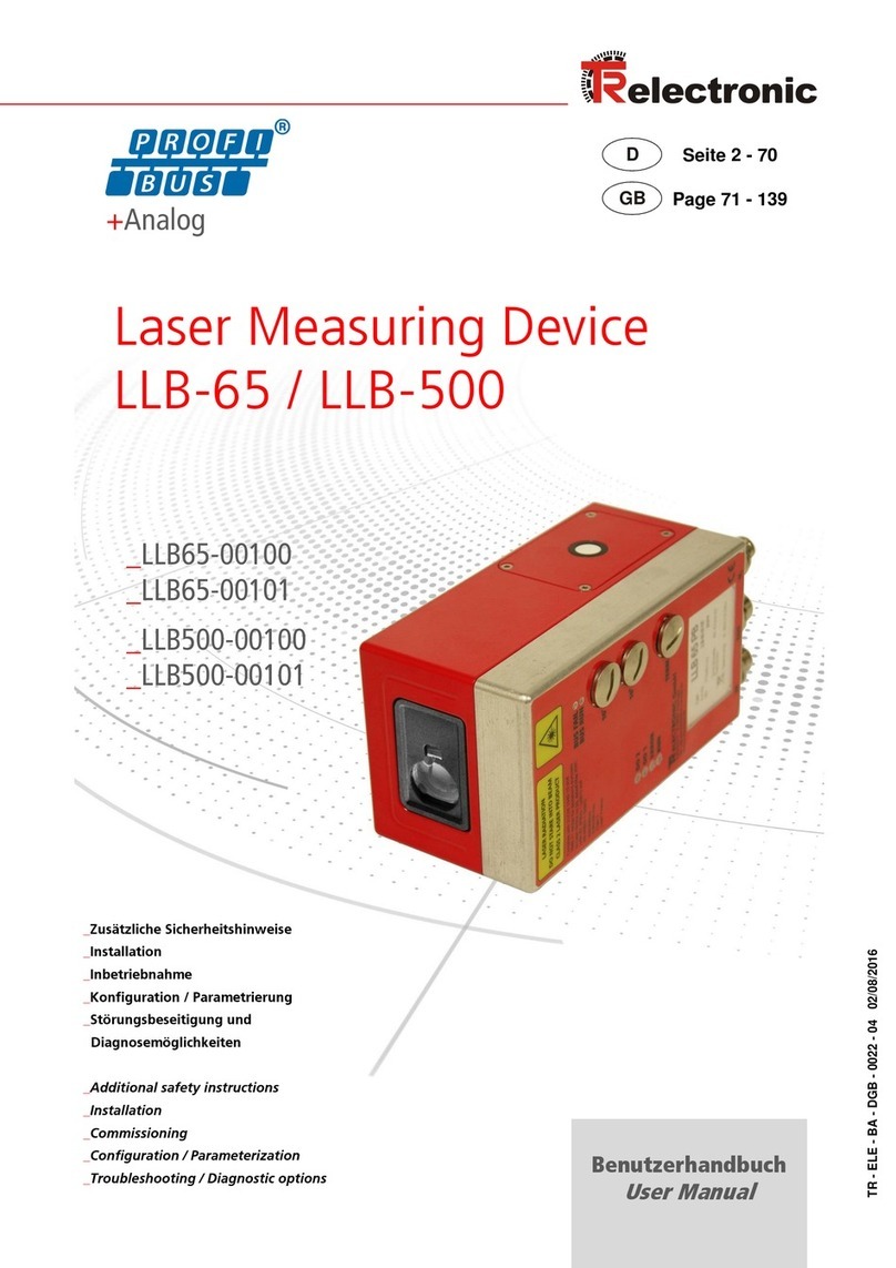
TR-Electronic LLB-502 Series User manual

TR - ELE - BA - DGB - 0028 - 02 04/06/2020
User Manual
_Basic safety instructions
_Introduction
_Technical data
_Electrical components
_Configuration
_Operation
_Command set
_Industrial Ethernet with exchangeable cover
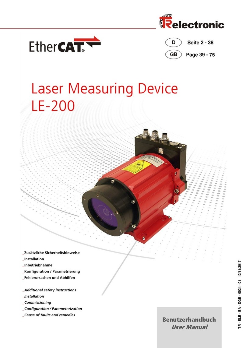
Laser Measuring Device
LLB-502
RS-232, RS-422/RS-485, Analog, SSI, Optional Ethernet Interfaces
Devices:
_LLB502-00001
_LLB502-00003
_LLB502-01111
_LLB502-01213
Exchangeable Interface Cover:
_LLB502-20700
_LLB502-20800
_LLB502-20900

TR-Electronic GmbH 2018, All Rights Reserved Printed in the Federal Republic of Germany
Page 2 of 102 TR - ELE - BA - DGB - 0028 - 02 04/06/2020
TR-Electronic GmbH
D-78647 Trossingen
Eglishalde 6
Tel.: (0049) 07425/228-0
Fax: (0049) 07425/228-33
email: [email protected]
www.tr-electronic.de
Copyright protection
This Manual, including the illustrations contained therein, is subject to copyright
protection. Use of this Manual by third parties in contravention of copyright
regulations is not permitted. Reproduction, translation as well as electronic and
photographic archiving and modification require the written content of the
manufacturer. Violations shall be subject to claims for damages.
Subject to modifications
The right to make any changes in the interest of technical progress is reserved.
Document information
Release date / Rev. date: 04/06/2020
Document / Rev. no.: TR - ELE - BA - DGB - 0028 - 02
File name: TR-ELE-BA-DGB-0028-02.docx
Author: STB
Font styles
Italic or bold font styles are used for the title of a document or are used for
highlighting.
Courier font displays text, which is visible on the display or screen and software
menu selections.
< > indicates keys on your computer keyboard (such as <RETURN>).

Printed in the Federal Republic of Germany TR-Electronic GmbH 2018, All Rights Reserved
04/06/2020 TR - ELE - BA - DGB - 0028 - 02 Page 3 of 102
Contents
Contents.............................................................................................................................................. 3
Revision index .................................................................................................................................... 7
1 General information ........................................................................................................................ 8
Applicability............................................................................................................................. 81.1 EU Declaration of conformity.................................................................................................. 91.2 Abbreviations and definitions.................................................................................................. 91.3
2 Basic safety instructions................................................................................................................ 10
Definition of symbols and instructions.................................................................................... 102.1 Obligation of the operator before start-up............................................................................... 112.2 General risks when using the product .................................................................................... 112.3 Safety information's ................................................................................................................ 112.4 Laser classification ................................................................................................................. 132.5 2.5.1 Laser specification.................................................................................................. 13
Permitted use.......................................................................................................................... 142.6 Prohibited use/Limits to use.................................................................................................... 142.7 Hazards in use........................................................................................................................ 152.8 Warranty and liability .............................................................................................................. 162.9 Organizational measures...................................................................................................... 162.10 Personnel qualification; obligations ...................................................................................... 162.11 Maintenance ......................................................................................................................... 17
2.12 Service.................................................................................................................................. 172.13
3 Transportation / Storage................................................................................................................. 17
4 Introduction...................................................................................................................................... 18
Labeling .................................................................................................................................. 194.1 Components............................................................................................................................ 204.2 Validity .................................................................................................................................... 214.3
5 Technical data.................................................................................................................................. 21
Device specifications.............................................................................................................. 215.1 Physical dimensions of LLB device with standard hood......................................................... 235.2 Measuring accuracy definition................................................................................................ 235.3
6 Electrical components.................................................................................................................... 24
Power supply .......................................................................................................................... 256.1 6.1.1 Specifications & Wiring........................................................................................... 25
6.1.2 Shielding ................................................................................................................. 25
Reset push button................................................................................................................... 266.2 Status LED.............................................................................................................................. 266.3 Digital output........................................................................................................................... 276.4 6.4.1 Specifications.......................................................................................................... 27
6.4.2 Wiring...................................................................................................................... 28
Digital input............................................................................................................................. 286.5

Contents
TR-Electronic GmbH 2018, All Rights Reserved Printed in the Federal Republic of Germany
Page 4 of 102 TR - ELE - BA - DGB - 0028 - 02 04/06/2020
Analog output.......................................................................................................................... 286.6 6.6.1 Specifications.......................................................................................................... 29
6.6.2 Wiring...................................................................................................................... 30
RS-232 interface..................................................................................................................... 306.7 6.7.1 Specifications.......................................................................................................... 30
6.7.2 Wiring...................................................................................................................... 31
RS-422/485 interface.............................................................................................................. 316.8 6.8.1 Specifications.......................................................................................................... 32
6.8.2 Wiring RS-422......................................................................................................... 32
6.8.3 Wiring RS-485......................................................................................................... 33
SSI interface ........................................................................................................................... 336.9 6.9.1 Specifications.......................................................................................................... 34
6.9.2 Timing ..................................................................................................................... 34
6.9.3 Wiring...................................................................................................................... 35
USB interface........................................................................................................................ 366.10 6.10.1 Specifications & Wiring......................................................................................... 36
6.10.2 Installation............................................................................................................. 36
Industrial Ethernet interface.................................................................................................. 376.11 6.11.1 Specifications........................................................................................................ 37
6.11.2 Wiring.................................................................................................................... 37
7 Configuration................................................................................................................................... 38
Configuration process............................................................................................................. 397.1 7.1.1 Connection.............................................................................................................. 39
7.1.2 Configuration types................................................................................................. 40
7.1.3 Configuration example............................................................................................ 41
Operation modes.................................................................................................................... 417.2 7.2.1 Controlled mode...................................................................................................... 42
7.2.2 Stand-alone mode................................................................................................... 42
7.2.3 Error behavior......................................................................................................... 43
Measuring characteristic......................................................................................................... 447.3 Data output ............................................................................................................................. 457.4 7.4.1 User output format / protocol.................................................................................. 45
7.4.2 User gain / offset..................................................................................................... 46
7.4.3 Output filter (Distance / error)................................................................................. 46
7.4.4 Moving Target filter................................................................................................. 47
Factory settings....................................................................................................................... 487.5
8 Operation.......................................................................................................................................... 49
Measurement overview........................................................................................................... 498.1 Installation............................................................................................................................... 508.2 8.2.1 Connection of the device ........................................................................................ 50
8.2.2 Mounting of the device............................................................................................ 50
8.2.3 Mounting of reflective plate..................................................................................... 51
8.2.4 Alignment of the laser beam................................................................................... 51
Measuring performance influence .......................................................................................... 518.3 Prevention of erroneous measurements ................................................................................ 528.4 8.4.1 Rough surfaces....................................................................................................... 52
8.4.2 Transparent surfaces.............................................................................................. 52
8.4.3 Wet, smooth or high-gloss surfaces ....................................................................... 52

Printed in the Federal Republic of Germany TR-Electronic GmbH 2018, All Rights Reserved
04/06/2020 TR - ELE - BA - DGB - 0028 - 02 Page 5 of 102
8.4.4 Inclined, round surfaces.......................................................................................... 53
8.4.5 Multiple reflections.................................................................................................. 53
8.4.6 Influence of other Iaser beams, sun light and others.............................................. 53
Laser life time consideration................................................................................................... 548.5 Heating functionality ............................................................................................................... 54
8.6
9 Command set................................................................................................................................... 54
General................................................................................................................................... 549.1 9.1.1 Command termination............................................................................................. 54
9.1.2 Device identification N............................................................................................. 54
9.1.3 Parameter separator............................................................................................... 54
9.1.4 Set/Get commands................................................................................................. 55
9.1.5 Startup sequence.................................................................................................... 55
Operation commands ............................................................................................................. 569.2 9.2.1 Stop / Clear command (sNc).................................................................................. 56
9.2.2 Distance measurement (sNg)................................................................................. 56
9.2.3 Single sensor tracking (sNh)................................................................................... 56
9.2.4 Single sensor tracking with timer (sNh).................................................................. 57
9.2.5 Tracking with buffering –Start (sNf)...................................................................... 57
9.2.6 Read out –Tracking with buffering (sNq)............................................................... 58
9.2.7 Signal measurement (sNm)..................................................................................... 58
9.2.8 Temperature measurement (sNt) .......................................................................... 59
9.2.9 Read/Clear error stack (sNre, sNce)................................................................... 59
9.2.10 Laser on (sNo)...................................................................................................... 59
Configuration commands........................................................................................................ 60
9.3 9.3.1 Set communication settings (sNbr)........................................................................ 60
9.3.2 Set device ID (sNid)............................................................................................... 60
9.3.3 Set/Get analog output min level (sNvm).................................................................. 61
9.3.4 Set/Get analog output value in error case (sNve).................................................. 61
9.3.5 Set/Get analog output distance range (sNv).......................................................... 62
9.3.6 Set/Get digital output type (sNot) .......................................................................... 62
9.3.7 Set/Get digital output hysteresis (sN1, sN2)........................................................ 63
9.3.8 Set/Get digital input function (sNDI1)..................................................................... 64
9.3.9 Get digital input (sNRI)........................................................................................... 64
9.3.10 Set/Get configuration of RS-422/485 and SSI...................................................... 65
9.3.11 Set/Get error value of SSI output.......................................................................... 66
9.3.12 Set/Get measuring characteristic (sNmc).............................................................. 66
9.3.13 Set/Get measurement filter configuration (sNfi)................................................. 67
9.3.14 Set auto start configuration (sNA)......................................................................... 67
9.3.15 Set configuration parameters to factory default (sNd).......................................... 68
9.3.16 Save configuration parameters (sNs)................................................................... 68
Extended configuration commands ........................................................................................ 689.4 9.4.1 Set/Get user output format (sNuo) ......................................................................... 68
9.4.2 Set/Get user distance offset (sNuof)..................................................................... 69
9.4.3 Set/Get user distance gain (sNuga)....................................................................... 70
9.4.4 Set user mode (sNum)............................................................................................. 70
Information commands........................................................................................................... 719.5 9.5.1 Get software version (sNsv)................................................................................... 71
9.5.2 Get serial number (sNsn) ....................................................................................... 71

Contents
TR-Electronic GmbH 2018, All Rights Reserved Printed in the Federal Republic of Germany
Page 6 of 102 TR - ELE - BA - DGB - 0028 - 02 04/06/2020
9.5.3 Get device type (sNdt, dt).................................................................................. 71
9.5.4 Get device generation and type (dg)...................................................................... 72
Error codes ............................................................................................................................. 729.6
10 Industrial Ethernet with exchangeable cover............................................................................. 74
In
tr
od
u
ct
io
n
.......................................................................................................................... 7410.1 10.1.1 Product identification............................................................................................. 74
10.1.2 Components.......................................................................................................... 75
10.1.3 Validity................................................................................................................... 75
Technical data....................................................................................................................... 7610.2 10.2.1 Specifications........................................................................................................ 76
Electrical interfaces............................................................................................................... 7710.3 10.3.1 Power supply ........................................................................................................ 77
10.3.2 Ethernet ports ....................................................................................................... 78
10.3.3 Ribbon cable......................................................................................................... 78
10.3.4 Shielding............................................................................................................... 79
10.3.5 Status LED............................................................................................................ 80
Operation.............................................................................................................................. 8110.4 10.4.1 Installation............................................................................................................. 81
10.4.2 General functionality............................................................................................. 82
10.4.2.1 Cyclic / Acyclic data communication....................................................................................... 82
10.4.2.2 Control and configuration........................................................................................................ 83
10.4.3 Parameter description........................................................................................... 84
10.4.4 Startup / Shutdown procedure.............................................................................. 87
10.4.5 Firmware download............................................................................................... 87
PROFINET®.......................................................................................................................... 88
10.5 10.5.1 Specifications........................................................................................................ 88
10.5.2 Status LED............................................................................................................ 89
10.5.3 Parameter list........................................................................................................ 90
10.5.3.1 Cyclic process data................................................................................................................. 90
10.5.3.2 Acyclic communication............................................................................................................ 91
10.5.4 Configuration......................................................................................................... 92
10.5.4.1 Overview................................................................................................................................. 92
10.5.4.2 Device description file (GSDML)............................................................................................. 92
10.5.4.3 Software / Tools...................................................................................................................... 92
EtherNet/IP™........................................................................................................................ 9310.6 10.6.1 Specifications........................................................................................................ 93
10.6.2 Status
LE
D
........................................................................................................... 94
10.6.3 Parameter list........................................................................................................ 95
10.6.3.1 Cyclic process data................................................................................................................. 95
10.6.3.2 Acyclic communication............................................................................................................ 96
10.6.4 Configuration......................................................................................................... 97
10.6.4.1 Overview................................................................................................................................. 97
10.6.4.2 Electronic Data Sheet (EDS)................................................................................................... 97
10.6.4.3 Software / Tools...................................................................................................................... 97
EtherCAT®............................................................................................................................ 9810.7 10.7.1 Specifications........................................................................................................ 98
10.7.2 Status LED............................................................................................................ 99
10.7.3 Parameter list........................................................................................................ 100
10.7.3.1 Cyclic process data................................................................................................................. 100
10.7.3.2 Acyclic communication............................................................................................................ 101
10.7.4 Configuration......................................................................................................... 102
10.7.4.1 Overview................................................................................................................................. 102
10.7.4.2 EtherCAT Slave Information (ESI)......................................................................................... 102
10.7.4.3 Software / Tools...................................................................................................................... 102

General information
TR-Electronic GmbH 2018, All Rights Reserved Printed in the Federal Republic of Germany
Page 8 of 102 TR - ELE - BA - DGB - 0028 - 02 04/06/2020
1 General information
The User Manual includes the following topics:
Basic safety instructions
Transportation / Storage
Introduction
Technical data
Electrical components
Configuration
Operation
Command set
Industrial Ethernet with exchangeable cover
As the documentation is arranged in a modular structure, this User Manual is supplementary to other
documentation, such as product datasheets, dimensional drawings, leaflets etc.
The User Manual may be included in the customer's specific delivery package or it may be requested
separately.
Applicability1.1
This User Manual applies exclusively to the following measuring systems in combination with an
exchangeable interface cover.
Measuring system Series with RS-232, RS-422/485, Analog and SSI:
LLB502-00001
LLB502-00003
LLB502-01111
LLB502-01213
Exchangeable interface cover:
LLB502-20700, EtherNet/IP™
LLB502-20800, PROFINET®
LLB502-20900, EtherCAT®
The products are labeled with affixed nameplates and are components of a system.
The following documentation therefore also applies:
the operator's operating instructions specific to the system,
this User Manual

Printed in the Federal Republic of Germany TR-Electronic GmbH 2018, All Rights Reserved
04/06/2020 TR - ELE - BA - DGB - 0028 - 02 Page 9 of 102
EU Declaration of conformity1.2
The LLB devices have been developed, designed and manufactured under observation of the
applicable international and European standards and directives.
A corresponding declaration of conformity can be requested from TR-Electronic GmbH.
The manufacturer of the product, TR-Electronic GmbH in
D-78647 Trossingen, operates a certified quality assurance system in accordance with ISO 9001.
Abbreviations and definitions1.3
AOI
Add-On Instructions (used for EtherNet/IP) are a kind of predefined function
blocks to assist customers by doing calculations with the EtherNet/IP™ adapter
data in “Studio 5000®” software (Rockwell Automation).
ASCII
American Standard Code for Information Interchange
EMC
Electro Magnetic Compatibility
EU
European Union
ESD
Electro Static Discharge
FLOAT
Single-precision floating point. Floating point with size: FLOAT32 –› 32 Bit
GSD / GSDML
Device description file written in XML format (used with PROFINET®)
IEC
International Electrotechnical Commission
Industrial
Ethernet
Industrial Ethernet interfaces e.g. PROFINET, EtherCAT, EtherNet/IP
(Real-Time Ethernet interfaces)
LLB
Laser Measuring Device
PLC
Programmable Logic Controller (e.g. Siemens S7)
R, R/W
Read access only (Read-only)
R / W
Read & Write access possible
SSBL
Second Stage Bootloader
SSI
Serial Synchronous Interface
STRING
Character string of variable length. Character size of one Byte.
UINT
Unsigned integer. Integer value with size: UINT8 –› 8 Bit (0...255), UINT16 –› 16
Bit (0...65 535), UINT32 –› 32 Bit (0...4 294 967 295)
VDE
Association for Electrical, Electronic & Information Technologies

Basic safety instructions
TR-Electronic GmbH 2018, All Rights Reserved Printed in the Federal Republic of Germany
Page 10 of 102 TR - ELE - BA - DGB - 0028 - 02 04/06/2020
2 Basic safety instructions
The following instructions are to enable the person responsible for the LLB device,
and the user of the instrument, to anticipate and avoid operational hazards.
The LLB device is made to be integrated into technical systems. Basic technical
training is therefore essential. This device may only be operated by trained
personnel.
The person responsible for the instrument must ensure that all users understand
these instructions and adhere to them.
If the LLB device is part of a system, the manufacturer of such a system is
responsible for all safety related issues, such as the manual, labeling and
instruction.
Definition of symbols and instructions2.1
means that death or serious injury can occur if the required precautions are
not met.
means that minor injuries can occur if the required precautions are not met.
means that damage to property can occur if the required precautions are
not met.
indicates important information or features and application tips for the product
used.
means that eye injury can occur from laser light if the stated precautions are not
met.
means that eye injury can occur from laser light if the stated precautions are not
met.

Printed in the Federal Republic of Germany TR-Electronic GmbH 2018, All Rights Reserved
04/06/2020 TR - ELE - BA - DGB - 0028 - 02 Page 11 of 102
Obligation of the operator before start-up2.2
As an electronic device the measuring system is subject to the regulations of the EMC Directive.
It is therefore only permitted to start up the measuring system if it has been established that the
system/machine into which the measuring system is to be fitted satisfies the provisions of the EU EMC
Directive, the harmonized standards, European standards or the corresponding national standards.
General risks when using the product2.3
The product, hereinafter referred to as "LLB device"or "LLB sensor", is manufactured according to
state-of-the-art technology and accepted safety rules. Nevertheless, improper use can pose a
danger to life and limb of the user or third parties, or lead to impairment of the measuring
system or other property!
Only use the measuring system in a technically faultless state, and only for its designated use, taking
safety and hazard aspects into consideration, and observing this User Manual! Faults which could
threaten safety should be eliminated without delay!
Safety information's2.4
Danger of physical injury and damage to property !
Do not point the viewfinder directly at the sun, the viewfinder functions
as a magnifying glass and can injure eyes and/or cause damage
inside the LLB.
De-energize the system before carrying out wiring work or opening
and closing electrical connections.
Do not carry out welding if the measuring system has already been
wired up or is switched on.
Ensure that the laser warning symbol on the measuring system is well
visible anytime.
No use of accessories from other manufacturers.
Ensure that the area around the assembly site is protected from corrosive
media (acid, etc.).
The measuring system contains electrostatically endangered circuit elements
and units which can be destroyed by an improper use.
Contacts of the measuring system connection contacts with the fingers are
to be avoided, or the appropriate ESD protective measures are to be
applied.

Basic safety instructions
TR-Electronic GmbH 2018, All Rights Reserved Printed in the Federal Republic of Germany
Page 12 of 102 TR - ELE - BA - DGB - 0028 - 02 04/06/2020
Disposal
If disposal has to be undertaken after the life span of the device, the
respective applicable country-specific regulations are to be observed.
Cleaning
Clean the lens opening of the measuring system regularly with a damp
cloth. Do not use any aggressive detergents, such as thinners or
acetone!
Eye injury from laser radiation!
The measuring system functions with a red light laser Class 2. In the
case of Class 2 laser devices, the eye is not endangered if the exposure
to the laser radiation is very brief (up to 0.25 s) and accidental. For this
reason, devices of this class can be used without additional protective
measures, provided the application does not require one to look into the
laser beam deliberately for longer periods, i.e. 0.25 s, or to look
repeatedly into the laser beam or the reflected laser beam.
The existence of the blinking reflex for the protection of the eyes may not
be assumed. Therefore eyes should be closed consciously, or the head
should be turned away immediately!
The measuring system must be installed in such a way that the exposure
of persons to the laser beam can only occur accidentally.
The laser beam must only extend as far as is necessary for the range
measurement. The beam must be limited at the end of the useful range
by a target area in such a way as to minimize the danger from direct or
diffuse reflection.
The area outside the operating range where the unshielded laser beam
falls should be limited as far as possible and should remain out of
bounds, particularly in the area above and below eye level.
Heed the laser safety regulations according to DIN EN 60825-1 in their
most current version.
Observe the legal and local regulations applicable to the operation of
laser units.

Printed in the Federal Republic of Germany TR-Electronic GmbH 2018, All Rights Reserved
04/06/2020 TR - ELE - BA - DGB - 0028 - 02 Page 13 of 102
Laser classification2.5
The LLB device produces a visible laser beam, which emerges from the front of the instrument.
It is a Class 2 laser product in accordance with:
IEC/EN 60825-1:2014 ”Radiation safety of laser products”
It is a Class II laser product in accordance with:
FDA 21 CFR 1040.10 and Laser Notice 50 (US Department of Health and Human Service,
Code of Federal Regulations)
Laser Class 2/II products
Do not stare into the laser beam or direct it towards other people unnecessarily. Eye protection is
normally afforded by aversion responses
including the blink reflex.
Looking into the laser beam may be hazardous to the eyes.
Do not look into the laser beam. Make sure the laser is aimed above or
below eye level. (particularly with fixed installations, in machines, etc.).
Do not look directly into the beam with optical aids (binoculars,
telescopes) can be hazardous
2.5.1 Laser specification
Standard applied
IEC/EN 60825-1:2014
Emitted wavelength
620...690 nm (typical 655 nm)
Beam divergence
0.16 x 0.6 mrad
Pulse duration
0.2...0.8 x 10-9 s
Max. radiant power
1 mW
Laser power measurement uncertainty
±5%

Basic safety instructions
TR-Electronic GmbH 2018, All Rights Reserved Printed in the Federal Republic of Germany
Page 14 of 102 TR - ELE - BA - DGB - 0028 - 02 04/06/2020
Permitted use2.6
The permitted use of the D-Series device is: Measuring distances in an atmosphere appropriate for
permanent human habitation.
Prohibited use/Limits to use2.7
Prohibited use or ignoring limits to use can lead to injury, malfunction,
and material damage.
It is the duty of the person responsible for the instrument to inform the
user about hazards and how to counteract them.
The D-Series devices must not be operated until the user has been
adequately instructed.
Prohibited use:
Use of the instrument without instruction
Use outside the stated limits
Deactivation of safety systems and removal of explanatory and hazard
labels
Opening of the equipment, except to open the cover for access to the
screw terminal
Carrying out modification or conversion of the product
Operation after failure in operation
Use of accessories from other manufacturers without the express
approval of Dimetix
Aiming directly into the sun
Deliberate dazzling of third parties; also in the dark
Inadequate safeguards at the surveying location (e.g. when measuring
on roads, etc.)
Environmental limits to use. The device must not be used in
environments such as but not limited to:
Aggressive vapor or liquids (salt, acid, poison, etc.)
Snow and rain
Radiation (radioactive, heat, etc.)
Explosive atmosphere
High-gloss measurement surfaces
Limits to use by application. The device must not be used in applications
such as but not limited to.
Aerospace (Aviation & Space flight)
Nuclear technology
Further limits to use. See chapter 4 Technical data on page 12.

Printed in the Federal Republic of Germany TR-Electronic GmbH 2018, All Rights Reserved
04/06/2020 TR - ELE - BA - DGB - 0028 - 02 Page 15 of 102
Hazards in use2.8
The absence of instruction, or the inadequate provision of instruction,
can lead to incorrect or prohibited use, and can give rise to accidents
with far-reaching personal, material and environmental consequences.
All users must follow the safety instructions given by the manufacturer
and the directions of the person responsible for the instrument.
Beware of erroneous distance measurements if the instrument is
defective or if it has been dropped or has been misused or modified.
Carry out periodic test measurements, particularly after the instrument
has been subject to abnormal use, and before, during and after
important measurements.
Make sure the LLB device optic is kept clean.
If labels are hidden when the LLB device is installed, this could lead to
dangerous situations.
Always ensure the visibility of LLB device labels at all times or add labels
in accordance with the local safety regulations.
When using the instrument for distance measurements or for positioning
moving objects (e.g. cranes, building equipment, platforms, etc.)
unforeseen events (e.g. breaking the laser beam) may cause erroneous
measurements.
Only use this product as a measuring sensor, not as a control device.
The system must be configured and operated in such a way that no
damage will occur in the event of an erroneous measurement,
malfunction of the device or power failure due to installed safety
measures (e.g. safety limit switch).
Operate the equipment appropriately in accordance with the regulations
in force.
Always prevent access to the equipment by unauthorized personnel.
Be careful when pointing a telescope towards the sun, because the
telescope functions as a magnifying glass and can injure eyes and/or
cause damage inside the LLB device.
Do not point the telescope directly at the sun.

Basic safety instructions
TR-Electronic GmbH 2018, All Rights Reserved Printed in the Federal Republic of Germany
Page 16 of 102 TR - ELE - BA - DGB - 0028 - 02 04/06/2020
Warranty and liability2.9
The General Terms and Conditions ("Allgemeine Geschäftsbedingungen") of TR-Electronic GmbH
always apply. These are available to the operator with the Order Confirmation or when the contract is
concluded at the latest. Warranty and liability claims in the case of personal injury or damage to
property are excluded if they result from one or more of the following causes:
Non-designated use of the measuring system.
Improper assembly, installation, start-up and programming of the measuring system.
Incorrectly undertaken work on the measuring system by unqualified personnel.
Operation of the measuring system with technical defects.
Mechanical or electrical modifications to the measuring systems undertaken autonomously.
Repairs carried out autonomously.
Third party interference and Acts of God.
Organizational measures2.10
The User Manual must always be kept accessible at the place of use of the measuring system.
In addition to the User Manual, generally applicable legal and other binding accident prevention
and environmental protection regulations are to be observed and must be mediated.
The respective applicable national, local and system-specific provisions and requirements must
be observed and mediated.
The operator is obliged to inform personnel on special operating features and requirements.
The personnel instructed to work with the measuring system must have read and understood
the User Manual, especially the chapter “Basic safety instructions” prior to commencing work.
The nameplate and any prohibition or instruction symbols applied on the measuring system
must always be maintained in a legible state.
Do not undertake any mechanical or electrical modifications on the measuring system, apart
from those explicitly described in this User Manual.
Repairs may only be undertaken by the manufacturer or a facility or person authorized by the
manufacturer.
Carry out periodic test measurements, particularly after the instrument has been subject to
abnormal use, and before, during and after important measurements. Make sure the LLB device
optics are kept clean.
Personnel qualification; obligations2.11
All work on the measuring system must only be carried out by qualified personnel.
Qualified personnel includes persons, who, through their training, experience and instruction, as
well as their knowledge of the relevant standards, provisions, accident prevention regulations
and operating conditions, have been authorized by the persons responsible for the system to
carry out the required work and are able to recognize and avoid potential hazards.
The definition of “Qualified Personnel” also includes an understanding of the standards VDE
0105-100 and IEC 364 (source: e.g. Beuth Verlag GmbH, VDE-Verlag GmbH).
Define clear rules of responsibilities for the assembly, installation, start-up and operation. The
obligation exists to provide supervision for trainee personnel!

Printed in the Federal Republic of Germany TR-Electronic GmbH 2018, All Rights Reserved
04/06/2020 TR - ELE - BA - DGB - 0028 - 02 Page 17 of 102
Maintenance2.12
The LLB device is almost maintenance free. The only thing you have to do is to clean the surfaces of
the lenses.
Dirty sensor optics can cause erroneous measurements.
The sensor can be contaminated by Dust, Oil, Ice, Water etc.
In dirty environments try to reduce contamination by design.
Regularly check sensor optics and clean if necessary.
Inadequate cleaning methods can damage the sensor optics.
Look after the surfaces of the lenses with same care that you would
apply to spectacles, cameras and field glasses.
Clean the optical parts (small laser output glass and the round lens) only
with a clean soft glasses cleaning cloth and avoid scratching of the
optical parts. All other cleaner or resolvent are not allowed.
Service2.13
If you need to service the device, please contact TR-Electronic for instructions.
The warranty is void if the device is opened except the exchangeable cover of the
screw terminal. Removing the label is also understood as opening.
3 Transportation / Storage
Notes on transportation
Do not drop the device or expose it to strong shocks!
Device contains an optical system with glass elements.
Only use the original packaging!
The wrong packaging material can cause damage to the device during transportation.
Storage
Storage temperature: see product data sheet
Store in a dry place

Introduction
TR-Electronic GmbH 2018, All Rights Reserved Printed in the Federal Republic of Germany
Page 18 of 102 TR - ELE - BA - DGB - 0028 - 02 04/06/2020
4 Introduction
The LLB sensors are powerful distance-measuring instrument for integration into industrial
applications. They allow accurate and contactless distance measurement over a wide range using the
laser beam reflection on a measuring surface / target:
Figure 1: Standard application for measuring distances
Key features:
●Measurement range 0.05 up to 500 m
●Measuring accuracy up to ±1.0 mm (at 2)
●High measurement speed (up to 250 Hz, 1000 Hz output rate)
●Several serial interfaces (RS-232, RS-422 / RS-485, SSI and USB)
●Exchangeable cover for Industrial Ethernet (PROFINET®, ETherNet/IP™ or EtherCAT®interface as
accessorie)
●Connection of up to 100 sensors on a single RS-422 / RS-485 line
●Wide range of power supply (12...30 VDC)
●Programmable analog output (0/4...20 mA)
●One programmable digital input (DI1)
●Two programmable digital outputs (DO1 and DO2)
●Digital output for error signalization (DOE)
●Selectable digital output type (NPN, PNP, Push-Pull)
●4 LED's for status signaling
●ASCII protocol to control external displays
●Screw terminal for easy connection of the LLB sensors
●IP65 (protected against ingress of dust and water)
●Wide range of operating temperature (down to -40°C and up to +60°C, for devices with extended
temperature range)
●Visible red laser, laser class II (<0.95 mW)
●Configuration software “LLB-Utility”
●Accessories for easy use of the sensor
Use of controls, adjustments or performance of procedures other than
those specified in this Technical Reference Manual may result in
hazardous radiation exposure.
For easy starting with the device, please download and use the free configuration
software “LLB-Utility” with the link “www.tr-electronic.de/f/zip/TR-ELE-SW-MUL-0001“
or from the Support DVD.

Introduction
TR-Electronic GmbH 2018, All Rights Reserved Printed in the Federal Republic of Germany
Page 20 of 102 TR - ELE - BA - DGB - 0028 - 02 04/06/2020
Components4.2
Figure 3: Sensor components with detail information
1)
Reset push button
7)
Product label (for more details, see chapter 4.1)
2)
Screw terminal block & plug. For conductor
cross section 0.14...1.5 mm2.
(Power supply, digital input / output, analog
output, RS-232 and RS-422 / RS-485 / SSI)
8)
Status LED's (Power, error, digital outputs)
9)
Industrial Ethernet interface
10)
USB 2.0 Mini-B
3)
Shield tab for an adequate receptacle
11)
Exchangeable cover (Used for optional interfaces)
4)
Slot hole for installation and alignment
(M4 or M3 screws)
12)
Valve diaphragm
5)
Hexagon socket set screw for sensor
alignment
13)
Cable gland M16 x 1.5 mm
(Cable diameter: 5...10 mm, tool size: 20 mm)
6)
Sensor front
(Laser beam output and receiver lens)
14)
Screws, Philips Slotted Combo
(Philips size 1, slot size 2)
Take precaution against electrostatic discharge (ESD) when
exchangeable cover is open.
Generally the sensor with removed exchangeable cover is a sensitive
device and can be damaged by electrostatic discharge.
Only handle the device properly grounded and with care.
No warranty will be granted on improper handling and / or ESD caused
problems.
The warranty is void if the device is opened except the exchangeable cover.
Removing the label is also understood as opening.
This manual suits for next models
7
Table of contents
Other TR-Electronic Measuring Instrument manuals

TR-Electronic
TR-Electronic LLB65-00600 User manual

TR-Electronic
TR-Electronic LE-25 User manual

TR-Electronic
TR-Electronic LE-25 User manual

TR-Electronic
TR-Electronic LE-200 User manual

TR-Electronic
TR-Electronic LE-25 User manual

TR-Electronic
TR-Electronic LE-200 User manual

TR-Electronic
TR-Electronic LE-200 User manual

TR-Electronic
TR-Electronic CEH-110 User manual

TR-Electronic
TR-Electronic LLB 502 User manual

TR-Electronic
TR-Electronic LE-25 User manual