TESTO ASET15 1 User manual

testo ASET15 1
User Manual

2

Content
3
Content
1Declaration of Warranty ............................................................................................... 5
1.1. Type of Designation .......................................................................................................................5
1.2. Manufacturer ................................................................................................................................5
1.3. Warranty .......................................................................................................................................5
2Precautions ................................................................................................................... 5
2.1. Foreword.......................................................................................................................................5
2.2. Liabilities .......................................................................................................................................5
2.2.1. Liability to Content...............................................................................................................6
2.3. Copyright ©...................................................................................................................................6
3Safety ............................................................................................................................ 6
3.1. Risk Types......................................................................................................................................6
3.1.1. Aerosol Contamination.........................................................................................................6
3.1.2. Hot Surfaces –Burn Hazards.................................................................................................6
3.1.3. Electrical Safety.................................................................................................................... 6
3.1.4. Mechanical Shock.................................................................................................................6
3.2. Labels and Explanations.................................................................................................................7
4System Overview........................................................................................................... 8
4.1. Dilution and Conditioning .............................................................................................................. 8
4.1.1. Principle...............................................................................................................................8
4.1.2. ThermoDilution....................................................................................................................8
4.2. Definitions ..................................................................................................................................... 9
4.3. Abbreviation, Units and Symbols.................................................................................................... 9
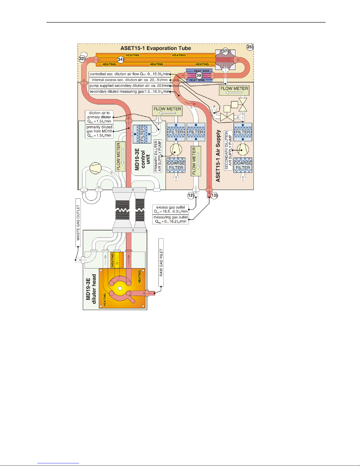
4.4. The System .................................................................................................................................. 10
4.5. Control Elements and Connections............................................................................................... 11
4.5.1. Important Remarks ............................................................................................................ 11
4.5.2. Front View ......................................................................................................................... 11
4.5.3. Gas Connectors.................................................................................................................. 12
4.5.4. Rear View........................................................................................................................... 13
5Installation and Setup ................................................................................................. 14
5.1. Integrating testo MD19-3E into the testo ASET15-1...................................................................... 14
5.2. Gas/Aerosol Connections............................................................................................................. 15
5.2.1. Quick Couplings at the front of testo ASET15-1................................................................... 15
5.2.2. Connect a Sensor to the Measuring Gas Inlet of the Evaporation Tube................................ 15
6Operating Instructions ................................................................................................ 16
6.1. Start Up....................................................................................................................................... 16
6.2. Evaporation Tube Heating Up Procedure...................................................................................... 16
6.3. Flows and Control LED's in Air Supply Part.................................................................................... 17
6.3.1. Signal LED Information ....................................................................................................... 18
6.3.2. Flow Settings and Dilution Factors...................................................................................... 18

Content
4
6.3.3. Influence of Instrumentation Connected to the Additional ET Inlet Port.............................. 18
6.4. Remote Operation ....................................................................................................................... 19
7Electrical Connections ................................................................................................. 20
7.1. Mains Supply ............................................................................................................................... 20
7.2. Analog/Digital Interface ............................................................................................................... 20
7.3. Remote Control ........................................................................................................................... 22
8Maintenance and Calibration...................................................................................... 22
8.1. Evaporation Tube......................................................................................................................... 22
8.2. Parts with Limited Lifetime .......................................................................................................... 22
8.3. Storage, Acclimatization............................................................................................................... 22
8.4. Operation Environment Requirements......................................................................................... 23
9Appendix ..................................................................................................................... 24
9.1. Extent of Delivery ........................................................................................................................ 24
9.2. Specification, Technical Data........................................................................................................ 24
9.3. Thermophoretic Losses................................................................................................................ 25
9.4. Definitions, Units and Conversion Table ....................................................................................... 26
10 Designation of All testo ASET15-1 Air Supply / Evaporation Tube Elements............... 27

1 Declaration of Warranty
5
1Declaration of Warranty
Manual Version History:
Version: V1.1
Date: September 2016
1.1. Type of Designation
This user manual refers to the instrument type and version as listed below. It replaces all
previously dated user manuals for this instrument.
Type: testo ASET15-1
1.2. Manufacturer
Testo SE & Co. KGaA
Testo-Strasse 1
79853 Lenzkirch
Germany
Tel: +49 7653 681 5062
Fax: +49 7653 681 95062
web: www.testo-particle.com
email:sales-nanoparticle@testo.de
For technical support contact your local service contractor or Testo techsupport.
email:support-nanoparticle@testo.de
1.3. Warranty
Testo SE & Co. KGaA warrants that this product adheres to the specified properties for a period
of twelve (12) months from the date of delivery.
Excluded from the warranty are all parts subjected to normal wear as any fuses, batteries or
other consumable parts. Also excluded are: Defects resulting from abnormal use, in particular
outside the intended purpose; lack of maintenance; improper use or malicious damage. Warranty
is void if actions are carried out which are not described in the documentation nor authorized by
Testo SE & Co. KGaA.
Testo SE & Co. KGaA does not provide any warranty on finished goods manufactured by others.
Only the original manufacturer's warranty applies.
There are no user-serviceable parts inside testo ASET15-1 and some very sensitive parts. Do not
open your testo ASET15-1, as you may damage it. Warranty is voided if the case is opened and
warranty-seal is broken.
Parts repaired or replaced as a result of repair services are warranted to be free from defects in
workmanship and material, under normal use, for 90 days from the date of shipment.
2Precautions
2.1. Foreword
This manual guides you through the installation, starting up, operation and maintenance
procedures of the testo ASET15-1. In detail you will find information about the system as
safety
functionality of the testo ASET15-1, technical information and specifications
installation of the testo ASET15-1 and accessories
handling, operation, maintenance and troubleshooting
Follow the instructions provided by this manual for safe and proper operation of the testo
ASET15-1 Air Supply / Evaporation Tube.
Before installing and operating the testo ASET15-1, the operator or service has
to read carefully this manual. For improper function, damages or injuries caused
by ignoring the instructions by this manual no liabilities are accepted.
2.2. Liabilities
Testo SE & Co. KGaA accepts no liability to improper function or injury caused by
neglecting the instructions provided by this manual or instructed person.
improper installation, operation, application, or maintenance.
operation by untrained staff.

3 Safety
6
any technical modification not carried out by Testo SE & Co. KGaA or an authorized
service partner.
use of not genuine spare parts.
2.2.1. Liability to Content
The content of this manual is generated with most accurateness. Testo SE & Co. KGaA does not
guarantee completeness, correctness and being up to date. Testo SE & Co. KGaAreserves the
right to revise the content of the manual at any time and without notice.
Follow the guidelines below to ensure proper operation of the instrument:
Read this instruction manual before installation and operation.
Always use genuine replacement parts supplied by Testo SE & Co. KGaA.
For operating the testo MD19-3E Rotating Disk Diluter integrated in the testo ASET15-1,
refer to the testo MD19-3E user manual.
2.3. Copyright ©
All work and contents done or generated by Testo SE & Co. KGaAare subject of the German
copyright © and law for intellectual property. This copyright includes all specification data of the
instrument or part of it, electrical and fluidic and mechanical schematics, pictures, diagrams and
text. Copying, editing, publishing or any other utilisation requires a written agreement of
Testo SE & Co. KGaA.
3Safety
3.1. Risk Types
The following diagram shows typical risks that could cause damage or injury while handling the
testo ASET15-1 Air Supply / Evaporation Tube.
Fig.3.1 : risk types
3.1.1. Aerosol Contamination
Toxic aerosols may escape from the device, if the excess and measuring gas ports are not
properly connected to the sensors downstream or an offtake.
3.1.2. Hot Surfaces –Burn Hazards
The evaporation tube is heated up to 400°C/752°F. Therefore, the pipes and other parts on the
rear side of the device may be hot and must not be touched. Always ensure good air circulation
around the heated parts. Do not use the device if the fan for gas cooling on the rear side of the
device does not work properly.
3.1.3. Electrical Safety
When in operation any electrical equipment can produce dangerous voltages. Failure to observe
the warnings may result in serious injury or damage. It is, therefore, mandatory that only suitably
qualified personnel use this instrument. Satisfactory and safe operation of this instrument calls for
proper handling in transportation, storage, installation as well as careful control and maintenance.
3.1.4. Mechanical Shock
Parts of the Instrument are thermally insulated by a quartz glass tube that may be damaged
when exposed to intense mechanical shock. The device should be handled with care.

3 Safety
7
3.2. Labels and Explanations
When operating the testo ASET15-1, the user always is operating under certain risk factors as
electricity, hot surfaces, and the aerosols which are processed by the dilution and conditioning
system. Therefore the testo ASET15-1 includes several safety features. Nevertheless, some
precautions still need to be taken to ensure safe and reliable operation. Listed labels, Caution
and Warning are explained in general, and the further specific labels refer to type of hazard and
danger.
Caution
Caution means be careful. If you do not follow the manual instruction you might
cause an instrument or accessories damage, but no human injury. Also Caution
refers to important information about installation, operation and maintenance.
Warning
Warning means that improper operation could cause a serious human or
instrument damage or injury with consequence of irrevocable instrument
damage.
Electric Shock
Hazardous voltage. Contact may cause electric shock or burn. Turn off and lock
out system power before servicing.
Electric Ground
This sign indicates that the mains connector and cabinet ground are connected
to protective earth PE.
Skin Burn
Hot surface. Do not touch. To avoid possible skin burns, wear heat protection
gloves or turn heating off and allow surfaces to cool down before servicing.
Ensure good air circulation around labeled parts.
Aerosol
Aerosols containing invisible nanoparticles and toxic exhaust gases are handled.
Some aerosols may escape from the testo ASET15-1 if the excess gas and
measuring gas ports are not thoroughly connected to an offtake and the aerosol
sucking sensors.

4 System Overview
8
4System Overview
4.1. Dilution and Conditioning
4.1.1. Principle
testo ASET15-1 Air Supply / Evaporation Tube is an accessory for the testo MD19 which is the
Rotating Disk Diluter with external diluter head for performing the primary dilution as close as
possible to the aerosol source.
This combination complies with the method of ThermoDilution according to the regulation for
nanoparticle measurement UN-ECE R83 and R49. ThermoDilution with testo MD19 and testo
ASET15-1 separates sampling, dilution and conditioning of the aerosol into the following steps:
Primary dilution of combustion engine emissions from tail pipe or CVS with the testo
MD19-diluter. testo ASET15-1 generates the primary dilution air for the testo MD19-
diluter with a calibrated and controlled flow of 1.5l/min.
Removal of volatile particles in the Evaporation Tube where the temperature can be
adjusted up to 400°C (recommended heating temperature according to GRPE-
draft =300°C). No recondensation takes place in the cooling down zone assuming the
measuring gas is below the dew point after primary dilution.
Secondary dilution in an adjustable dilution factor range from 1 to 11 in a mixing
assembly whose construction minimizes thermophoretic losses. The primary diluted
measuring gas from the primary testo MD19-3E diluter with a flow of 1.5l/min and the
evaporation tube is diluted with secondary dilution air generated in testo ASET15-1. Its
flow is adjustable in a calibrated range of 0...15l/min corresponding to a dilution factor
range of 1...11. The total measuring gas flow, up to 16.5l/min enables the user
furthermore to connect nanoparticle instrumentation, which consumes higher measuring
gas flows than can be drawn from the testo MD19-diluter, whose diluted measuring gas
flow is limited to 5l/min.
4.1.2. ThermoDilution
Fig. 4.1 shows a schematic plot of the mass concentration of a volatile compound against the
temperature of the surrounding gas. In a dilution tunnel both the concentration and the
temperature of the substance are reduced (path A B). During dilution, the compound passes
its dew point and nucleates into nanodroplets (curve N). Subsequent secondary dilution (B D)
will reduce the number concentration of the droplets, but is unable to evaporate them, because of
a hysteresis effect between nucleation and evaporation.
A strategy to avoid the mere formation of nanodroplets is direct sampling from the hot exhaust in
combination with hot dilution (A C). Given a sufficient dilution factor, the volatiles will not
nucleate during subsequent cooling (C D) even though the same final state is assumed as
through dilution tunnel and secondary dilution (A BD). However, in some applications e.g.
measurement on CVS tunnel, direct sampling is not possible, and nanodroplets already exist in
the gas sample (B). In those cases the diluted gas sample (D) has to be heated above the
evaporation point of the compound (C D, crossing curve E). Like with hot dilution, the
compound remains in vapor phase upon subsequent cooling
(C D). The combination of diluter and heater (B DCD) is known as ThermoDiluter.
Hot dilution is realized in Testo rotating disk diluters. Together with Testo rotating disk diluter
testo MD19-3E the testo ASET15-1 forms a complete ThermoDiluter system.
Fig.4.1: volatile mass diagram

4 System Overview
9
4.2. Definitions
Air Supply
primary and secondary dilution air supply part of testo ASET15-1
Evaporation
Tube
thermally insulated stainless steel tube with electronically controlled
heater on the testo ASET15-1 rear side for heating up the primarily
diluted measuring gas.
Raw gas
undiluted aerosol from the emission source
Measuring gas
primary or secondary diluted aerosol from the emission source
(combustion engine or CVS).
Primary dilution
Takes place in testo MD19-3E rotating disk diluter before the
measuring gas enters into the evaporation tube.
Secondary
dilution
Dilution of the primarily diluted and thermally conditioned measuring
gas at the outlet of the evaporation tube.
4.3. Abbreviation, Units and Symbols
testo ASET15-1
Air Supply Evaporation Tube; 15 = 15l/min air supply; 1 = version 1
CVS
Constant Volume Sample –fullstream dilution tunnel in vehicle test
benches
DF
Dilution Factor in secondary dilution: DF = (QAS + QMD)/ QMD
PCRF
Particle Concentration Reduction Factor
LED
Light Emitting Diode –used as signal lamps at the front of the testo
ASET15-1
l/min (STP)
Standard liter per minute: unit for gas volume flow at Standard
Temperature and Preasure (STP: 1013,25 hPa, 0°C)
testo MD19-3E
Type designation for Testo rotating disk diluters
QMD
primary diluted measuring gas flow from the testo MD19-3E primary
diluter
QAS
secondary dilution air flow from the air supply part of testo ASET15-1
QMG
secondary diluted measuring gas flow to the connected instrumentation
QEX
excess secondary diluted measuring gas gas flow

4 System Overview
10
4.4. The System
Fig.4.4 : function principle –pneumatic diagram of testo ASET15-1 with integrated testo
MD19-3E
12 Excess measuring gas output
13 Measuring gas output
25 Safety cage to inhibit skin contact to the hot parts situated at the rear or the unit
32 Additional evaporation tube inlet port
34 Thermally insulated evaporation tube
37 Secondary dilution mixing chamber
39 Heat sink
The testo ASET15-1 is power supplied by one phase electricity. An internal pump feeds filtered
air to the integrated testo MD19-3E, where raw gas is added and therewith primary dilution is
carried out.
The testo ASET15-1 Air Supply / Evaporation Tube with integrated testo MD19-3E
Rotating Disk Diluter can be combined with the testo CU-2 digital control unit and therewith

4 System Overview
11
remote controlled via Ethernet. The components are mounted in standard 19" cases and can
easily be integrated in a test bench equipped with 19" racks and Ethernet connections.
Fig. 4.2 shows all pneumatic components of the ThermoDilution system consisting of the testo
ASET15-1 and the testo MD19-3E. The pathways of dilution air, raw gas and diluted measuring
gas are visible.
No external dilution air is needed. Ambient air is drawn and filtered inside the case of the testo
ASET15-1 and fed to the testo MD19-3E where it is needed to dilute some raw gas. The primarily
diluted gas then returns to the testo ASET15-1. In the evaporation tube volatile particle
components are transformed into the gas phase. Finally a certain adjustable amount of
secondary dilution air is added in order to reduce the gas temperature, to enhance the measuring
gas flow, and to achieve particle concentrations within the range of the particle sensors set
downstream the dilution system.
4.5. Control Elements and Connections
4.5.1. Important Remarks
The testo ASET15-1 and testo MD19-3E are constructed for dilution and conditioning of exhaust
or flue gas from combustion processes in diesel engines, light oil burners or wood or coal
combustion. It may also be used for gases or aerosols emerging from other processes.
Electric Shock
When in operation, any electrical equipment can produce dangerous voltages.
Ignoring these warnings may result in serious injury or damage of the equipment.
It is mandatory that only suitably qualified personnel are allowed to work on this
instrument. Satisfactory and safe operation of this instrument necessitates
proper handling in transportation, storage and installation as well as careful
control and maintenance.
Skin Burn
Parts of the testo MD19-3E diluter head are heated up to 160°C / 320°F. Also
the outer surface of the testo ASET15-1 evaporation tube becomes a hot surface
when the temperature inside is increased up to 400°C / 752°F. Always use heat
protection gloves when handling hot parts.
Aerosol
Diluted or undiluted aerosol may escape from the system if the gas return port of
the testo MD19-3E is are not thoroughly connected to an offtake or if the
additional evaporation tube inlet port 33) of testo ASET15-1 is open. If some gas
escapes at the excess gas port 12) it is filtered and contains no particles but may
contain diluted gaseous toxic exhaust components.
4.5.2. Front View
In Fig. 4.3 all ports and operating elements situated at the front side of testo ASET15-1 with
integrated testo MD19-3E are shown. The testo ASET15-1 elements are described below the
figure while the testo MD19-3E controls are explained in the testo MD19-3E operations manual.
Fig.4.3 : front view of testo ASET15-1 with integrated testo MD19-3E

4 System Overview
12
1 Air supply control elements: primary dilution air feed and secondary dilution
2 Evaporation Tube control elements (conditioner parameters)
3 Remote control LED green: remote dark: local
4 Secondary dilution air supply ON/OFF switch
5 Sec. dil. air supply LED green: OK red: flow error dark: OFF
6 testo MD19-3E air supply ON/OFF switch
7 testo MD19-3E air supply LED green: OK red: flow error dark: OFF
8 10 turn potentiometer for secondary dilution air supply setting
9 High excess gas flow LED yellow:excess gas flow>1.5l/min
10 Sufficient excess gas flow LED green: excess gas flow=0.3...1.5l/min
11 Low excess gas flow LED red: excess gas is critically low: <0.3l/min
12 Excess measuring gas output
13 Quick coupling for measuring gas output to sensor(s)
14 Heating current too high LED red: current too high (short circuit)
15 Heating current OK LED green: current within range
16 Heating current too low LED red: current too low (interrupt)
17 Evaporation tube heating ON/OFF swich
18 Actual evaporation tube temperature (red)
19 Evaporation tube temperature setpoint (green)
20 Temperature controller status field
21 Temperature controller control field
4.5.3. Gas Connectors
The excess gas port 12) and measuring gas port 13) of testo ASET15-1 can be connected to an
offtake and to the subsequent sensor(s) using the connectors shown in Fig. 4.4.
Fig.4.4 : excess and measuring gas connectors
22 Female gas coupling for connecting a 6mm ID tube to excess gas port
23 Male gas plug for connecting a 6mm ID tube to measuring gas port
(delivered with testo MD19-3E Rotating Disk Diluter)
Connecting any device to the front aerosol output of the testo MD19-3E would affect the flows
inside and therewith the dilution properties of the system. The testo MD19-3E is internally
connected to the testo ASET15-1 and no additional connection is needed. The gas plug 23) out
of the testo MD19-3E delivery is used to connect any measuring instrumentation to the testo
ASET15-1.

4 System Overview
13
4.5.4. Rear View
Fig. 4.5 and 4.6 show all testo ASET15-1 elements and connections which are situated at the
rear side of the unit. The hot parts are covered by a safety protection cage which has been
removed in Fig. 4.6.
Fig.4.5 : rear view of testo ASET15-1 with safety cage mounted
24 Safety cage fixation nuts
25 Safety cage to inhibit skin contact to the hot parts situated at the rear side of the unit
26 Digital/analog interface of the integrated testo MD19-3E rotating disk diluter
27 Digital/analog interface to connect the testo ASET15-1 to the CU-2 digital control unit
28 Fuse of the integrated testo MD19-3E:5A slow
29 Fuse of testo ASET15-1: 5A slow
30 Mains switch
31 Mains connector
32 Additional evaporation tube inlet port (closed)
Skin Burn
Hot surfaces are inside the heat protection cage. Always ensure good air
circulation around the rear of testo ASET15-1 when it is in operation. Always
wear heat protection gloves or turn heating off and allow surfaces to cool down
before removing the heat protection cage.
Fig.4.6 : rear view of testo ASET15-1 with safety cage removed
33 Evaporation Tube inlet
34 Thermally insulated evaporation tube
35 Electrical cable of the heater
36 Secondary dilution air inlet
37 Secondary dilution mixing chamber
38 Temperature sensor of the evaporation tube
39 Heat sink

5 Installation and Setup
14
40 Connection between mixing chamber and heat sink 39)
41 Fan for cooling the components integrated in the testo ASET15-1
42 Heat sink cooling fan
43 Measuring gas outlet connection to front panel
Aerosol
Never operate the testo ASET15-1 with open additional evaporation tube inlet
port 32). This port is only used for calibration issues. Any air or aerosol flow on
this port will influence the dilution conditions in the device. If the port is open
during operation, the environment of the unit may be contaminated by escaping
aerosols.
5Installation and Setup
Note: Numbers –e.g. 8) = secondary dilution setting potentiometer –refer to the operating
elements illustrated in chapter 4.5.
The testo ASET15-1 Air Supply / Evaporation Tube is a secondary dilution unit and cannot be
operated without an inserted primary testo MD19-3E Rotating Disk Diluter.
5.1. Integrating testo MD19-3E into the testo ASET15-1
The testo ASET15-1 without any primary diluter integrated is shown in Fig. 5.1. The testo MD19-
3E Rotating Disk Diluter can be plugged into the testo ASET15-1 housing if the pneumatic ports
at the rear side of the plug-in are equipped with the quick couplings shown in Fig. 5.2 .
Fig.5.1: testo ASET15-1 without integrated testo MD19-3E Rotating Disk Diluter
The control unit of the primary diluter is plugged into the testo ASET15-1 housing and fixed with
six screws located at the top and the bottom of the testo MD19-3E front panel. To remove the
testo MD19-3E from the testo ASET15-1 these screws have to be solved and the unit can be
pulled out.
Fig.5.2: Plug-in unit rear view with suitable quick couplings testo MD19-3E

5 Installation and Setup
15
5.2. Gas/Aerosol Connections
5.2.1. Quick Couplings at the front of testo ASET15-1
testo ASET15-1 is equipped with two quick coupling elements to connect the device to an excess
gas offtake (male coupling 12)) and to the subsequent sensor(s) (female coupling 13)). One
female excess gas coupling 22) is included in testo ASET15-1 delivery and one male measuring
gas plug 23) is delivered with testo MD19-3E rotating disk diluter. Both coupling elements are
also available from Testo SE & Co. KGaA.
Fig. 5.3 shows how the male plug of a tube is disconnected from the female quick coupling.
Pushing down the button at the top of the quick coupling will release the plug which can be pulled
out then.
Fig.5.3: handling of quick coupling at the front side
The plug catching ring will remain down when the plug is disconnected from the coupling. When
a plug is pulled in, the ring and button will jump up and automatically lock the plug. If the plug
cannot be inserted, the fixation ring might be in the wrong position. Push down the release button
and insert the plug again.
The excess gas connection 12) meets the same standard but male and female connectors are
exchanged.
5.2.2. Connect a Sensor to the Measuring Gas Inlet of the Evaporation Tube
The connection of a sensor e.g. a particle counter (CPC) to the additional evaporation tube inlet
port 32) might be of interest to measure the loss of volatile particles in the evaporation tube by
evaporation. To prepare the connection of the sensor proceed as follows:
Dismount the safety cage 25) by loosening the 5 nuts 24).
Remove the closing cover from the additional evaporation tube inlet port 32).
Mount the short stainless steel tube to the additional inlet using the Swagelock stainless
steel nut and the two PTFE ferrules. All these parts are included in the accessories.
Remount the safety cage before you connect your sensor to the steel tube.
Drawing measuring gas on the inlet to the evaporation tube reduces the flow in the evaporation
tube and influences therefore the setting of the dilution factor as explained in chapter 6.3.3.

6 Operating Instructions
16
6Operating Instructions
6.1. Start Up
Instructions in the following chapters are given for operation with an integrated
testo MD19-3E rotating disk diluter mounted in the left half of the testo ASET15-1
rack case.
For starting up some measurements using the dilution system consisting of the testo MD19-3E
and testo ASET15-1 follow these steps:
Connect the connector 31) at the rear side of the testo ASET15-1 case to mains supply.
The mains switch 30) should remain switched off. Details of the power supply are
described in chapter 7.
Prepare the testo MD19-3E Rotating Disk Diluter to be ready for operation according to
the testo MD19-3E manual. Connect its diluter head via pneumatical and electrical
connection to the control unit which has to be integrated into testo ASET15-1.
Connect the nanoparticle instrumentation to the measuring gas output 13) using the gas
connector plug 23) for tubes with inner diameter 6mm.
Connect the waste gas output of the testo MD19-3E to the exhaust or a separate offtake.
Connect the excess measuring gas output of the testo ASET15-1 12) to an exhaust
suction system
The two gases must be independently connected to the exhaust suction. The
pulsation of the testo MD19-3E pump might have an influence on the flow regulation
in the Air Supply of the testo ASET15-1.
The tube connected to testo MD19-3E pump outlet can fill with liquid from
condensation if the diluter head is connected to undiluted engine exhaust which is
cooled down on its way to the control unit.
Ensure the raw gas pump switch on the testo MD19-3E front panel and the testo MD19-
3E air supply switch 6), the dilution air supply switch 4), and the evaporation tube heating
switch 17) on the testo ASET15-1 front panel are all in OFF position.
Switch on the mains switch 30) at the rear side of the unit.
Switch on testo MD19-3E dilution air supply 6) at the testo ASET15-1 front panel. The
testo MD19-3E air supply LED 7) indicates if the electronically controlled dilution air flow
is within its specified tolerance of +/-3% (green) or not (red).
6.2. Evaporation Tube Heating Up Procedure
The temperature inside the evaporation tube 34) is measured in the gas stream and indicated on
the actual temperature display 18) at the top of the temperature controller which is shown in Fig.
6.1. The evaporation tube heating is activated and deactivated using switch 17). Heating only
makes sense if dilution air is supplied to the primary diluter and measuring gas passes the
evaporation tube. Nevertheless there is no risk of damage by overheating even if no gas passes
the evaporation tube.
Fig.6.1: TemperatureController

6 Operating Instructions
17
If the actual temperature display 18) shows , press in the control
field 21) during 2 sec to switch on the temperature controller.
Press and then and/or to change the temperature setpoint. If the desired
value is indicated by the setpoint display 19), safe by pushing again.
Switch on the evaporation tube heating with toggle switch 17) to connect the controller
power output to the heater.
The green heating current OK LED 15) indicates that supply voltage (24 VDC) is applied
to the heating and the current is within its tolerance.
If one of the red heating current LED's 14) or 16) lights, the current is too low or too high,
probably caused by a defective heating element or an interrupt in the electric circuit. The
evaporation tube should be switched off immediately and the device has to be checked
and repaired by the manufacturer or a local service provider.
Wait until the measured gas temperature 18) agrees with the set value 19) within +/-2°C.
During the heating up phase the heating current OK LED 15) lights continuously green.
The LED starts blinking in intervals of a few seconds when the measured gas
temperature approaches the set value. When the set value is reached the heating
on/off-duty cycle stabilizes on a ratio depending on the adjusted temperature.
Heating up times are approximately 2.5min from ambient to 200°C and 4min to 300°C.
Due to attachment of low volatile substances on its inner surface, the evaporation
tube may produce particles itself if operated at temperatures above the previous
operation point. In this case, the attached volatile material evaporates, and may
re-nucleate being measured by the connected instrumentation. When the
evaporation tube temperature is increased, it is recommended to run the testo
ASET15-1 with stopped rotating diluter disk but active testo MD19-3E dilution air
supply to rinse the tube with filtered air until no undesired particles are detected
anymore. This process may last up to 20 minutes.
6.3. Flows and Control LED's in Air Supply Part
Note: All flows mentioned in this manual are standard volume flows in [l/min] which means liters
per minute at standard conditions: 1013,25 hPa / 0°C.
testo ASET15-1 in its pneumatic function is an adjustable diluter where two calibrated flows QMD
and QAS are mixed in the secondary dilution mixing chamber 37). Fig. 6.2 shall help to
understand the setting of the secondary dilution air in the air supply part of testo ASET15-1.
Fig.6.2: secondary dilution flows
Measuring gas flow QMD (standard 1.5l/min) from the testo MD19-3E Rotating Disk Diluter enters
the secondary dilution mixing chamber. Secondary diluted measuring gas flow QMG is drawn from
the instrumentation connected on the measuring gas output 13).
It is evident that QAS must be adjusted to a value where QMD +QAS >QMG and therewith QEX >0 to
ensure no gas is sucked backwards through the excess gas tube and added to the measuring
gas.

6 Operating Instructions
18
6.3.1. Signal LED Information
The excess flow QEX =QMD +QAS −QMG is internally measured and examined in relation to three
criterions signalized with tree control LED's:
The sufficient excess flow LED 10) lights green if QEX is within the minimal excess
range 0.3...1.5l/min.
The high excess flow LED 9) lights yellow if QEX >1.5l/min. This means the excess gas
flow exceeds the minimal excess flow range. Depending on QEX a certain backpressure
can arise. At 16.5l/min excess gas (i.e. maximum secondary dilution and no measuring
gas drawn by a sensor) this backpressure can reach up to 16mbar.
The low excess gas flow LED 11) lights red if QEX <0.3l/min. The excess gas flow is
nearly zero and could even get negative due to slight flow changes. There is a certain
risk of ambient air sucked backwards through the excess gas tube and mixed to the
measuring gas.
6.3.2. Flow Settings and Dilution Factors
The primarily diluted flow QMD is adjusted and calibrated to a standard flow of 1.5l/min. This
amount of filtered dilution air is fed to the inserted primary diluter testo MD19-3E. It is added
there by some raw gas and returns then to the testo ASET15-1 for further conditioning.
QAS can be set on the scaled 10-turn secondary dilution air potentiometer 8) or via analog input
signal. The reading on the potentiometer from 1.00...11.00 and the input signal range
0...10VDC correspond to a flow QAS of 0...1 5l/min.
With QMD =1.5l/min the potentiometer reading corresponds directly to the secondary dilution
factor.
Examles:
E
x
a
m
p
l
e
s
:
pot. setting=2
QAS =(2–1)∙1.5l/min=1.5l/min
dilution factor DF=
DF
=
=2
pot. setting=5
QAS =(5–1)∙1.5l/min=6.0l/min
DF
=
=5
6.3.3. Influence of Instrumentation Connected to the Additional ET Inlet Port
If a sensor is connected to the additional evaporation tube inlet port 32) and draws a certain
amount of measuring gas, the flow in the evaporation tube is reduced and therewith the dilution is
affected. To calculate the secondary dilution factor, the flow drawn from the evaporation tube inlet
port has to be known. If this flow cannot be determined otherwise, it can be calculated as the
difference between the excess gas flow measured with and without the drawing sensor.
The excess gas flow can be measured on pin 5 of the testo ASET15-1 interface connector 27),
according to the pin assignment which is described in chapter 7.2.
1...5VDC relates to 0...5l/min excess gas flow. This means that a flow change of 1l/min causes
a voltage difference of 1.25VDC, or 1VDC corresponds to 0.8l/min:
respectively
Example:
A sensor S1 is connected to the additional evaporation tube inlet port 32).
A constant measuring gas flow QMG is drawn from the measuring gas outlet 13)
at the front panel. The testo ASET15-1 potentiometer 8) is set to 2.
If S1 is sampling, the voltage at pin 5 is UON = 2.13V
If S1 is not sampling, the voltage is UOFF = 2.50V
QS1 =
=0.3l/min
pot. setting=2QAS =(2–1)∙1.5l/min=1.5l/min
dilution factor DF=
=2.25 instead of 2.

6 Operating Instructions
19
Air Supply Local Operation
Start up the system following chapter 6.1 and heat up the evaporation tube.
Start the instrumentation connected to the testo ASET15-1 therewith the measuring gas
flow desired for the pending measurements is drawn from the measuring gas output 13).
Set the secondary dilution air supply potentiometer 8) on its mechanical zero position to
set the secondary dilution factor to 1.0 which actually means no secondary dilution.
Switch on the secondary dilution air supply 4). The secondary dilution air supply LED 5)
lights red first and turns to green after a few seconds to indicate the secondary air supply
pump working properly.
If the connected sensors draw less than 1.2 l/min, the sufficient excess measuring gas
flow LED 10) lights green as soon as the flows are stable. The testo MD19-3E raw gas
pump can be switched on and the measurements can start if the primary diluter is ready
and no secondary dilution is required e.g. due to too high concentrations in the
measuring gas or for reducing thermophoretic losses according to appendix A.3.
If a higher amout of measuring gas is drawn, the low measuring gas flow LED 11) lights
red indicating that the excess gas flow is below 0.3l/min or could even be negative which
would mean air was sucked backwards through the excess gas port 12) and mixed in an
undefined way with the measuring gas.
In this case enhance the secondary dilution flow QAS by adjusting the secondary dilution
air supply potentiometer 8) until the light signal changes to the green flow OK LED 10).
Increase the flow 0.1...0.3 potentiometer units over the limit where the green LED starts
to light to find the ideal measuring gas flow setting.
The secondary dilution can be used to increase the total dilution factor as well as to
reduce thermophoretic losses. If it is set as high as more measuring gas is conditioned
and provided than needed by the connected sensor(s), a certain back pressure can arise
in the measuring gas stream due to the filter in the excess gas tube. Therefore the high
excess gas LED 9) lights yellow if more than 1.5l/min pass the excess gas port. This
back pressure can reach up to 16mbar at maximum secondary dilution and zero
measuring gas flow.
The total particle concentration reduction factor PCRF is the product of the primary dilution factor
set at the testo MD19-3E, the secondary dilution factor set at the testo ASET15-1 and the inverse
of one minus the fraction which is not lost due to thermophoretic losses.
Example:
testo MD19-3E primary dilution factor: 30
testo ASET15-1 secondary dilution factor: 3
thermophoretic loss (see appendix A.3): 10% =0.1
PCRF=
=100
Note: When switching OFF the secondary dilution air supply switch 4), wait at least 10 seconds
before restarting in order to avoid short peak flows in the order of 20l/min on the measuring gas
output 13)
6.4. Remote Operation
Remote communication with testo ASET15-1 is possible with analog and digital inputs and
outputs at the digital/analog interface 27) at the rear side of the device. The signals on this
connector are described in chapter 7.2.
Besides the remote interface of the integrated testo MD19-3E Rotating Disk Diluter is connected
to the corresponding plug 26) at the rear side of the testo ASET15-1 case. The function and pin
assignment of this connector are the same as the ones of the connector at the rear side of the
testo MD19-3E stand alone case which are described in the testo MD19-3E user manual.

7 Electrical Connections
20
7Electrical Connections
7.1. Mains Supply
Connect the power cord plug to a grounded power socket. The IEC mains connector 31) on the
rear side of the testo ASET15-1 case includes the mains switch 30). The fuse holders 28) and
29) for integrated testo MD19-3E Rotating Disk Diluter and testo ASET15-1 itself are located on
the rear side of the laboratory case, besides the mains switch / mains connector. The one phase
power cord delivered with the instrument is equipped with a country-specific plug and protective
earth.
Mains supply voltage: 90 ... 240 VAC, 50/60 Hz, max. 600 VA
Fuse type testo MD19-3E: slow switching fuse 250V, 5A, t, 5 x 20 mm
Fuse type testo ASET15-1: slow switching fuse 250V, 5A, t, 5 x 20 mm
Warning
In case of a blown fuse, replace it only with the specified type of fuse. If the fuse is
repeatedly blown, the dilution unit must be sent to the manufacturer or to an
instructed service station for checking and repair.
Electric Shock
Make sure that the protecting ground pin of the country specific plug is correctly
connected to the protecting ground contact of your socket. If the plug is replaced,
ensure the yellow/green ground wire of the cable is properly connected to the new
ground pin or the case is otherwise connected to protective earth which is usually
indicated by the sign.
7.2. Analog/Digital Interface
The 25 pole D-Sub connectors at the rear side of the testo ASET15-1 case and the pin
assignment of the testo ASET15-1 remote interface 27) are shown in Fig. 7.1.
Fig.7.1: testo MD19-3E and testo ASET15-1 remote interfaces
The digital inputs and outputs are standard 5 V logic levels.
Digital inputs: High level: >3.0VDC low level: <0.7VDC
The load resistance of the device is Rin >10kΩ
Digital outputs: High level: 5.0+/-0.2VDC low level: <0.7VDC,
The source resistance of the device is Rout <3.5kΩ
The analog signals are 0...10VDC signals.
Analog inputs: The load resistance of the device is Rin >1.0MΩ
Analog outputs: The source current of output signals can be IS≤5mA.
D-
sub
pin
signal description
local
equivalent
or signal
analog
/digital
in-
/output
signal range
1
evaporation tube actual
temperature
disp. 18)
A
O
0...10VDC =
0...400°C
2
evaporation tube temperature
setpoint
disp. 19)
A
I
0...10VDC =
0...400°C
3
analog ground
A
0VDC for analog
inputs/outputs
4
evaporation tube current Iheat
too high
LED 14)
D
O
0VDC: OK 5VDC: Iheat
too high
Table of contents