Testomat 808 User manual

1
Testomat® 808
Online Analysis Instrument
for Water Hardness
Operating Instructions

Content
2
Content
Content.................................................................................................2
Important safety information .............................................................4
Intended use .........................................................................................4
Qualification of the staff ........................................................................4
Warning notices in these instructions ...................................................5
Notes and instructions to be observed ............................................5
General instructions..............................................................................5
Installation.............................................................................................6
Operation ..............................................................................................6
Cleaning................................................................................................6
De-installation .......................................................................................6
Disposal ................................................................................................6
Operating requirements........................................................................7
Scope of delivery ................................................................................7
Performance specifications...............................................................8
Indicators for Testomat® 808 instruments.............................................8
Functions of the operating and display elements...........................9
Switching Testomat® 808 on/off............................................................9
Front view Testomat® 808.....................................................................9
Operating elements/Function keys .....................................................10
Display elements/LEDs.......................................................................11
Installation.........................................................................................12
Installing Testomat®808.....................................................................12
Operating Testomat®808 in the pressure range 4 to 8 bar................12
Connecting the water inlet and outlet .................................................13
Water inlet...........................................................................................13
Water outlet.........................................................................................14
Connecting the power supply and devices .........................................14
Plant example Testomat® 808.............................................................15
Internal design Testomat®808............................................................16
Rear of the controller board................................................................16
Reset key S1.......................................................................................16
Function key S6 ..................................................................................16
Function key S7 ..................................................................................16
Slide switch T1....................................................................................17
Slide switch T2....................................................................................17
Plug connector J1 ...............................................................................17
Plug connector J2 ...............................................................................17
Plug connector J3 ...............................................................................17
Base circuit board Testomat®808 ......................................................18
Plug connector J2 ...............................................................................18
Plug connector J8 ...............................................................................18
Current interface .................................................................................18
Inputs DEL. EXT. and STOP ..............................................................19
Terminal block.....................................................................................19
Fuses ..................................................................................................19

Content
3
Connecting the mains voltage.............................................................20
Connecting the inputs and outputs .....................................................21
Description of the signal inputs......................................................23
Interfaces...........................................................................................23
Current interface .................................................................................23
Serial interface RS232........................................................................24
Description of the relay outputs......................................................24
Relay K3 –fault message...................................................................24
Relays K1 and K2 ...............................................................................24
Switching functions of the relays K1 and K2.......................................24
Commissioning.................................................................................26
Inserting the indicator bottle................................................................26
Bleeding the indicator lines.................................................................26
Opening the water inlet.......................................................................26
Instrument settings and analysis....................................................27
Instrument settings..............................................................................27
Selecting the indicator type and bottle size ........................................28
Carrying out an analysis .....................................................................28
Analysis process.................................................................................29
Further basic functions and settings..............................................30
Internal flushing...................................................................................30
External flushing .................................................................................30
Flush process –internal/external in manual mode.............................30
Interval pause .....................................................................................31
72 h operation (operation without permanent supervision) ...............32
Error messages/Troubleshooting ...................................................32
Alarm/Error message/Relay K3 ..........................................................32
Low water level ...................................................................................35
Measuring fault analysis .....................................................................35
Further possible instrument errors......................................................35
Maintenance ......................................................................................36
Service instructions.............................................................................37
Description of maintenance work........................................................37
Replacing the indicator bottle..............................................................37
Cleaning the measuring chamber and the sight-glass windows.........38
Pump head maintenance message ....................................................39
Testomat® 808 spare parts and accessories..................................41
Accessories - indicators......................................................................42
Technical data...................................................................................43
EC conformity Declaration..................................................................44
Product overview Testomat 2000®-Instruments ............................45

Important safety information
4
Important safety information
Please read these operating instructions carefully and completely
prior to working with the instrument.
Ensure that these operating instructions are always available for all
users.
These operating instructions must always be passed on to the new
owner should Testomat®808 change hands.
Always adhere to hazard warnings and safety information when
using reagents, chemicals and cleaning agents. Please adhere to
the respective safety data sheet! Download the safety data sheets
for the supplied reagents at http://www.heyl.de .
Intended use
Testomat®808 has been designed for use in the field of water treat-
ment (e.g. osmosis plants, electroplating, large boiler plants, laun-
dries, canteen kitchens). The feed water must be clear, colourless
and free of undissolved particles. The instrument is a limit value
measuring instrument which automatically monitors the residual total
hardness (water hardness) in water.
Always adhere to the performance limits stated in the section enti-
tled “Technical data”on page 43.
Always observe the application areas/application limits of the indi-
cators and the requirements of the medium being measured.
To ensure correct and intended usage, always read and understand
these instructions, especially the section entitled “Important safety
information”, prior to use.
The instrument is not used as intended if
it is used in areas not specified in these instructions.
it is used in areas which do not correspond to the ones described
in these instructions.
Qualification of the staff
Assembly and commissioning require fundamental electrical and
process engineering knowledge as well as knowledge of the respec-
tive technical terms. Assembly and commissioning should therefore
only be carried out by a specialist or by an authorised individual su-
pervised by a specialist.
A specialist is someone who due to his/her technical training, know-
how and experience as well as knowledge of relevant regulations can
assess assigned tasks, recognise potential hazards and ensure ap-
propriate safety measures. A specialist should always adhere to the
relevant technical regulations.

Notes and instructions to be observed
5
Warning notices in these instructions
The warning notices in these instructions warn the user about poten-
tial dangers to individuals and property resulting from incorrect han-
dling of the instrument. The warning notices are structured as follows:
Description of the type or source of danger
Description of the consequences resulting from non-observance
Preventive measures. Always adhere to these preventive
measures.
“DANGER” indicates an immediate hazardous situation which, if not
avoided, will result in death or serious injury.
“WARNING” indicates a potentially hazardous situation which, if not
avoided, could result in death or serious injury.
“CAUTION” indicates a potentially hazardous situation which, if not
avoided, could result in minor or moderate injuries or property dam-
age.
“NOTE” indicates important information. If this information is not ob-
served, it may result in an undesirable result or state.
Notes and instructions to be ob-
served
General instructions
Adhere to health and safety regulations, electrical equipment safe-
ty regulations, and environmental protection regulations valid in the
country of use and at the installation site.
Adhere to national and local regulations during installation and
commissioning.
Always protect the instrument against moisture and humidity. It
should never come into contact with condensation or splash water.
Do not carry out any changes or modifications at the instrument
which are not described in these instructions;
failure to adhere to
these instructions will negatively affect any warranty claims that
you make thereafter
.
WARNING
!
WARNING
!
NOTE
CAUTION
!
DANGER
!
SIGNAL WORD!

Notes and instructions to be observed
6
Installation
Always completely disconnect the relevant plant part before in-
stalling the instrument or connecting/disconnecting it to/from the
power supply. Secure the plant against reconnection.
Only connect the instrument to the mains voltage specified on the
rating plate.
Always observe technical data and ambient parameters.
Testomat®808 requires an interference free and stable power
supply. If necessary, use a mains filter to protect Testomat®
against interference voltages caused, e.g., by solenoid valves or
large motors. Never lay connecting cables parallel to power cables.
Operation
Ensure that the maximum electrical load capacity of the relay out-
puts is never exceeded.
Immediately switch off Testomat®808 and contact service staff if
malfunctioning occurs. The warranty will be void if you tamper with
or attempt to repair Testomat® 808. Repairs must be carried out by
authorised service staff.
Cleaning
Only use a dry, lint-free cloth for cleaning.
De-installation
Prior to de-installing a defective instrument, always write down a
description of the error (failure effect). It is only possible to repair a
defective instrument (irrespective of the warranty period) if it has
been de-installed and returned to us with a description of the error.
Use to the enclosed error log to describe the error and return it to
us together with the instrument. If the error log is no longer availa-
ble, download it at www.heyl.de.
Disposal
Dispose of the instrument in accordance with national regulations.
WARNING
!
NOTE

Scope of delivery
7
Operating requirements
In order for Testomat®808 to operate reliably, use Heyl Tes-
tomat®indicators in the pH-range 4 –10.5!
Only operate the instrument with the parameters specified under
“Technical data”.
With Testomat®instruments for water hardness monitoring, larger
quantities of heavy metal ions in the softened water might influ-
ence the colour reaction, especially iron above 0.5 mg/I, copper
above 0.1 mg/I and aluminium above 0.1 mg/l (brownish-red col-
our display).
If the measuring water contains more than 20 mg/I CO2(carbonic
acid), incorrect evaluations cannot be excluded. In this case, use
an aerator (e.g. special Heyl accessories).
The concentration of influencing contents can be determined by
using our colorimetric TESTOVAL®test kit
Important! Excessive carbonate hardness and also the ex-
istence of disinfectants in the water can result in erroneous
evaluations.
Careful handling of the instrument increases both its operational
reliability and service life! Therefore, carry out a visual inspection
at regular intervals as described below:
- Has the use-by-date of the indicator expired?
- Are the hose connections of the dosing pump free of leaks?
- Is there any air inside the dosing hoses?
- Are all the water connections free of leaks?
- Are the doors of the instrument closed properly?
- Is the instrument heavily soiled?
- Are the measuring chamber and the drain duct/drain hose
clean?
Trouble-free operation is only possible when maintenance is car-
ried out on a regular basis! For more information, please refer to
the section entitled “Maintenance”on page 36.
If problems occur, please refer to the section entitled “Error mes-
sages/Troubleshooting”on page 32.
Scope of delivery
1x Testomat® 808
1x plastic bag containing a screw cap with a hole and an insert for the
screw cap of the indicator bottle
2x fuse
1x operating instructions
Special accessories (available separately): Filter inlet, candle filter as
well as pressure regulator
Required hose connections and supply lines for Testomat® 808 are
available from Heyl.
NOTE
CAUTION
!

Performance specifications
8
Performance specifications
Testomat®808 is used for the automatic monitoring of residual total
hardness (water hardness) in water. The limit value to be monitored
is determined by the indicator selection.
Limit values for residual hardness of 0.02 –10.0 °dH* deter-
minable by indicator selection
Analysis start:
- Automatic interval mode
(interval pause can be set from 0 –60 minutes)
- External control
- Manual start
Extended operating periods due to 500 ml indicator storage
bottle
RS232 interface for optional firmware update
Indicators for Testomat® 808 instruments
Indicators with various limit values are available for the application of
Testomat®808 instruments according to operational requirements.
Indicator
type
Monitoring
range
Limit value LEDs
(good/poor display)
Measuring result
(information on water quality)
300 –330
Residual hard-
ness
0.02 –10 °dH
“GOOD” green
Residual hardness < indicator limit
value
“POOR” red
Residual hardness > indicator limit
value
All indicator types are available in two bottle sizes (100 ml and
500 ml). Please refer to the section entitled “Testomat® 808 spare
parts and accessories” on page 41 for a detailed list of the individual
indicator types with the respective article numbers.

Functions of the operating and display elements
9
Functions of the operating and dis-
play elements
Operating statuses and measuring results are displayed at Testomat®
808 via LEDs. The input keys for operating the instrument are posi-
tioned below the LEDs.
Switching Testomat® 808 on/off
(1) Power switch
Switch the instrument on/off using the green power switch (after
opening the housing cover on the front of the instrument).
(2) Instrument fuse (internal)
These fuses protect Testomat® 808 and the outputs against over-
loads and short circuits.
DPlease refer to the sections entitled “Fuses”on page 19 and
“Error messages/Troubleshooting” on page 32 for descriptions of
the fuses.
Front view Testomat® 808

Functions of the operating and display elements
10
Operating elements/Function keys
All operating elements/function keys are assigned twice. The respec-
tive function is triggered by a short or long (min. 2 seconds) key
press.
Key 1
(manual)
Short key press: Starts an analysis (manual start),
the respective LED flashes.
Long key press: Switches the dosing pump for bleed-
ing the pipes on/off. The LED illuminates while the
pump is running.
Key 2
(flushing)
Short key press*: Switches the internal flush valve
on/off, the respective LED flashes as long as the
valve is open.
Long key press*: Activates an external flush valve via
relay K1 (on/off). The LED above key 2 and LED K1
illuminate as long as the external valve is activated.
Key 3
(standby)
Short key press: Switches the standby function
on/off. The respective LED flashes if standby is ac-
tive.
Long key press: The respective LED displays wheth-
er operation is possible for longer than 72 h (opera-
tion without supervision).
Key 4 (horn)
Short key press: Acknowledges current er-
rors/alarms.
Long key press: Sets the indicator display from 0% to
100% (the LEDs 10% to 90% illuminate).
Note: It is not possible to enter any indicator level.
* only in standby mode

Functions of the operating and display elements
11
Display elements/LEDs
All measuring results as well as activated functions are displayed at
Testomat®808 via LEDs.
The LEDs above the function keys illuminate/flash when the respec-
tive function is activated.
The LED illuminates if the instrument is switched
on via the power switch on the front of the instru-
ment and is operating.
Limit value LEDs (red/green) for displaying the
measuring result:
Limit value not achieved => green LED illuminates
Limit value exceeded => red LED illuminates
When a new measuring is running, the result of
the previous measurement flashes.
The LEDs K1 and K2 display the status of the
relays. They illuminate if the respective relay has
been switched (also see the section entitled
“Switching functions of the relays K1 and K2” on
page 24)!
10% –90%: These LEDs display the calculated
filling level of the indicator bottle (also see the
section entitled “Measuring fault analysis” on page
35).
E4 –E1: These LEDs display current errors after
simultaneously pressing key 3 and key 4 for ap-
prox. 2 seconds (also see the section entitled
“Error messages/Troubleshooting” on page 32).
E4 flashes: The pump head has been in operation
for 150 hours and must be replaced (also see the
section entitled “Pump head maintenance mes-
sage”on page 39)
Cancelling error messages/warning messages
Press key 4 to acknowledge the messages and,
if necessary, eliminate the cause of the fault.
NOTE
red
green
Installation
12
Installation
Risks resulting from incorrect installation!
Install Testomat® 808 at a location where it is protected against
dripping or splash water, dust and aggressive substances –e.g. in
a control cabinet or on a suitable wall.
Information for trouble-free operation
Install Testomat® 808 vertically and without mechanical stress.
Install Testomat® 808 at a vibration-free site.
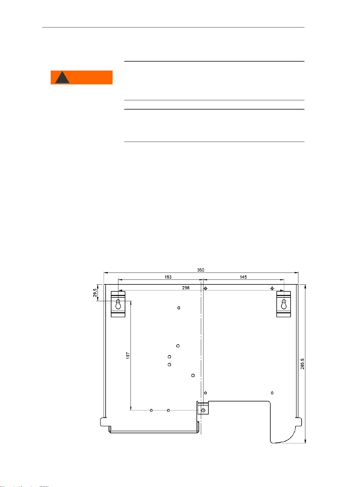
Installing Testomat®808
Select an installation site where the water inlet hose can be kept as
short as possible (max. 5 m).
Drill the mounting holes as shown in the drawing below.
Use three screws to attach the instrument at a suitable position on
the wall.
NOTE
WARNING
!

Installation
13
Operating Testomat®808 in the pressure
range 4 to 8 bar
Prior to installation, please check whether a higher operating pres-
sure (between 4 and 8 bar) is required. Use a pressure controller (art.
no. 37602) for ranges between 4 and 8 bar. Optimum operation of
Testomat®808 is achieved with operating pressure of between 2 and
4 bar.
Information for trouble-free operation
The water pressure must be between 1 and 8 bar; a pressure re-
ducer should be used for the 4 to 8 bar range (special accesso-
ries). This pressure regulator must be set under flow pressure!
Avoid strong pressure fluctuations.
Connecting the water inlet and outlet
Information for trouble-free operation
Ensure there are no foreign particles bigger than 150 µm which
caused blocking. Use our candle filter (Art. No. 37583) at the front
end of the device if you have problems with blocking.
The measuring water temperature must be between 10°C and
40°C.
For water temperatures above 40°C, install the KCN type cooler in
the supply line of Testomat®808.
Water inlet
The measuring water is taken from the main water line of the water
treatment plant and fed to the inlet connection of Testomat®808. The
instrument is equipped with a plug connector for plastic hoses 6/4 x 1
(external diameter 6 mm/ internal diameter 4 mm, wall thickness 1
mm) as standard).
Install the connection for the branch line of Testomat®808 directly
at the main water line directly after the water treatment plant.
Always lay the branch line connection vertically upwards in order to
prevent dirt particles from entering the instrument from the main
water line.
We recommend you to install a manually operated stop valve (see
figure “Plant example Testomat® 808” on page 15) in the branch
line to Testomat®808.
Use an opaque plastic hose 6/4 x 1 (max. length 5 m) for the water
inlet .
Flush the supply line to remove any dirt particles.
Outlet
Inlet
NOTE

Installation
14
When using a cooler
The hot water can cause burns and damage wetted parts of
Testomat® 808.
Water outlet
The feed water flows through the measuring chamber to the drain via
the outlet hose.
Remove the red plug from the outlet connection.
Connect the outlet connection of Testomat®808 to an outlet hose
(internal diameter 4 mm).
Feed the hose to an outlet.
Transportation plug!
The outlet is sealed with a plug to prevent leakage during transporta-
tion. Keep and store the plug for possible transportation at a later
date.
Connecting the power supply and devices
Risk of electric shocks during installation!
If the power supply is not disconnected prior to installation, it may
result in personal injuries, destruction of the product or damage to
plant parts.
Always disconnect the relevant plant parts before installing Tes-
tomat® 808.
Only use tested cables with sufficient cross-sections for the con-
nections.
Risk of damages caused by electromagnetic fields!
If Testomat® 808 or the connecting cables are installed parallel to
power cables or in close proximity to strong electromagnetic fields,
the instrument may be damaged or measurements incorrect.
Ensure that connecting cables are as short as possible.
Always install connecting cables and power cables separately.
Connect the instrument to the protective earth conductor (for
230/115 VAC).
Shield the instrument against strong electromagnetic fields.
CAUTION
!
WARNING
!
NOTE
NOTE

Installation
15
Plant example Testomat® 808

Installation
16
Internal design Testomat®808
Rear of the controller board
Keys 1 to 4 are located at the front of the board. Please refer to the
section entitled “Functions of the operating and display elements”on
page 9 for a detailed description of its operating system and the dis-
play elements.
The following function keys and slide switches as well as plug con-
nectors are also provided:
Reset key S1
Use reset key S1 to execute a reset, i.e. to reset the firmware of
Testomat®808 after an update.
Function key S6
Use function key S6 to set the interval pause between measure-
ments. Please refer to the section entitled “Interval pause” on page
31 for an overview of possible switching positions and interval paus-
es. (The standard setting is 3.)
Function key S7
Use function key S7 to set the switching behaviour of the relays
K1 and K2. Please refer to the section entitled “Switching functions of
the relays K1 and K2” on page 24 for an overview of possible switch-
ing positions. (The standard setting is 3.)
S7
S6

Installation
17
Switch position
The respective switch position is read after evaluating a measuring
result and after a reset.
Slide switch T1
Switch position LEFT: If the slide switch is in the left position
and the instrument is switched on or the reset key pressed while the
instrument is switched on, the microcontroller executes the operating
program (firmware).
Switch position RIGHT: If the slide switch is in the right position
and the instrument is switched on or the reset key pressed while the
instrument is switched on, the instrument is set to a mode which ena-
bles a firmware update via the serial interface.
If your instrument requires a firmware update, Heyl will provide you
with further detailed information.
Switch position
The switch position is only read immediately after a reset.
Slide switch T2
Use the slide switch T2 to determine the size of the indicator bot-
tle. The following indicator bottle sizes are possible:
Indicator
Switch position
100 ml bottle
Left
500 ml bottle
Right
Switch position
The status of the slide switch T2 is read after resetting the indicator
display to 100% and after a reset.
Plug connector J1
The plug connector J1 is a programming interface. It is not im-
portant for instrument operation.
Plug connector J2
The connection to the base circuit board is established via the plug
connector J2 using a ribbon cable.
Plug connector J3
The connection to the RS232 interface is established via the plug
connector J3 using a ribbon cable. Please refer to the section
entitled “Serial interface RS232” on page 24 for a detailed descrip-
tion.
NOTE
Switch position right
(delivery status)
NOTE
Switch position left
(delivery status)
NOTE
!

Installation
18
Base circuit board Testomat®808
The illustration above provides an overview of the design of the base
circuit board.
Plug connector J2
The connection to the controller board is established via the plug
connector J2 using a ribbon cable.
Plug connector J8
The power switch is connected at plug connector J8 .
Current interface
Please refer to the section entitled “Interfaces”on page 23 for a de-
scription of the current interface .

Installation
19
Inputs DEL. EXT. and STOP
Please refer to the section entitled “Description of the signal inputs”
on page 23 for a description of the inputs “Delete externally” and
“Stop”.
Terminal block
Please refer to the sections entitled “Connecting the mains voltage”
on page 20 and “Connecting the inputs and outputs” on page 21 for a
description of the terminal block .
Fuses
The following fuses can be found on the base circuit board.
No.
Designation
Function
Comment
F1
Relay protection fuse
4 A
F2
Primary fuse
230 V / 0.1 A
115 V / 0.2 A
24 V / 1 A
F3
Secondary fuse
1 A
Please refer to the section entitled “Testomat® 808 spare parts and
accessories” on page 41 for the article numbers when reordering fus-
es.

Installation
20
Connecting the mains voltage
Only connect the instrument to the specified mains voltage. Refer to
the rating plate for the appropriate mains voltage. Connect the cables
as follows:
Open the housing cover and subsequently loosen the two fas-
tening screws at the top and bottom of the door to the interior of
Testomat® 808. The door can now be opened and the terminal box
accessed.
Feed the cable through one of the cable glands underneath the
housing into the terminal box.
Feed the cable through one of the cable glands underneath the
housing into the terminal box.
Subsequently pull back the cable until the bush has been turned
over (2).
Connect the power supply to the terminals PE, N, L.
To do so, insert the conductors into the round cable input at the
terminal block. Ensure that the strands are held securely in the
terminals.
To loosen the connection, insert a screwdriver into the square
opening without force in order to open the terminal. Once the ter-
minal has been opened, remove the conductor.
Terminal
description
Type
Function
Comment
PE
IN
Mains protective earth (4x)
Only with mains
115/230 V !
N
(U)
L
(V)
IN
Mains, N=neutral (U=24 V)
Mains, L=live (V=24 V)
Mains input 50-60 Hz
24 V / 115 V / 230 V
n
l
OUT
Neutral, switched (3x)
Live, switched (3x)
Mains for consumers,
max. 4 A
Table of contents
Popular Analytical Instrument manuals by other brands


Fluke
Fluke 434 user manual

Teledyne
Teledyne T802 Operation manual

iWorX
iWorX GA-200 Series Technical note

Enotec
Enotec OXITEC 5000 Series Installation and operation manual

ANALOX
ANALOX O2 Portable Operator's manual

Bühler technologies
Bühler technologies GAS 222.31 Ex2 Installation and operation instruction


