Leader Cam R90 User manual

R90

1

2
Références produit / Product references
D11.04.304
LEADER Cam R90 Reel 90m
English p 38

1
1. INTRODUCTION................................................................................................................................2
1.1. General functions ........................................................................................................................................................3
1.2. Detailed technical specifications .................................................................................................................................3
2. LEADER CAM R90 DESCRIPTION .................................................................................................4
2.1. CONTENTS................................................................................................................................................................4
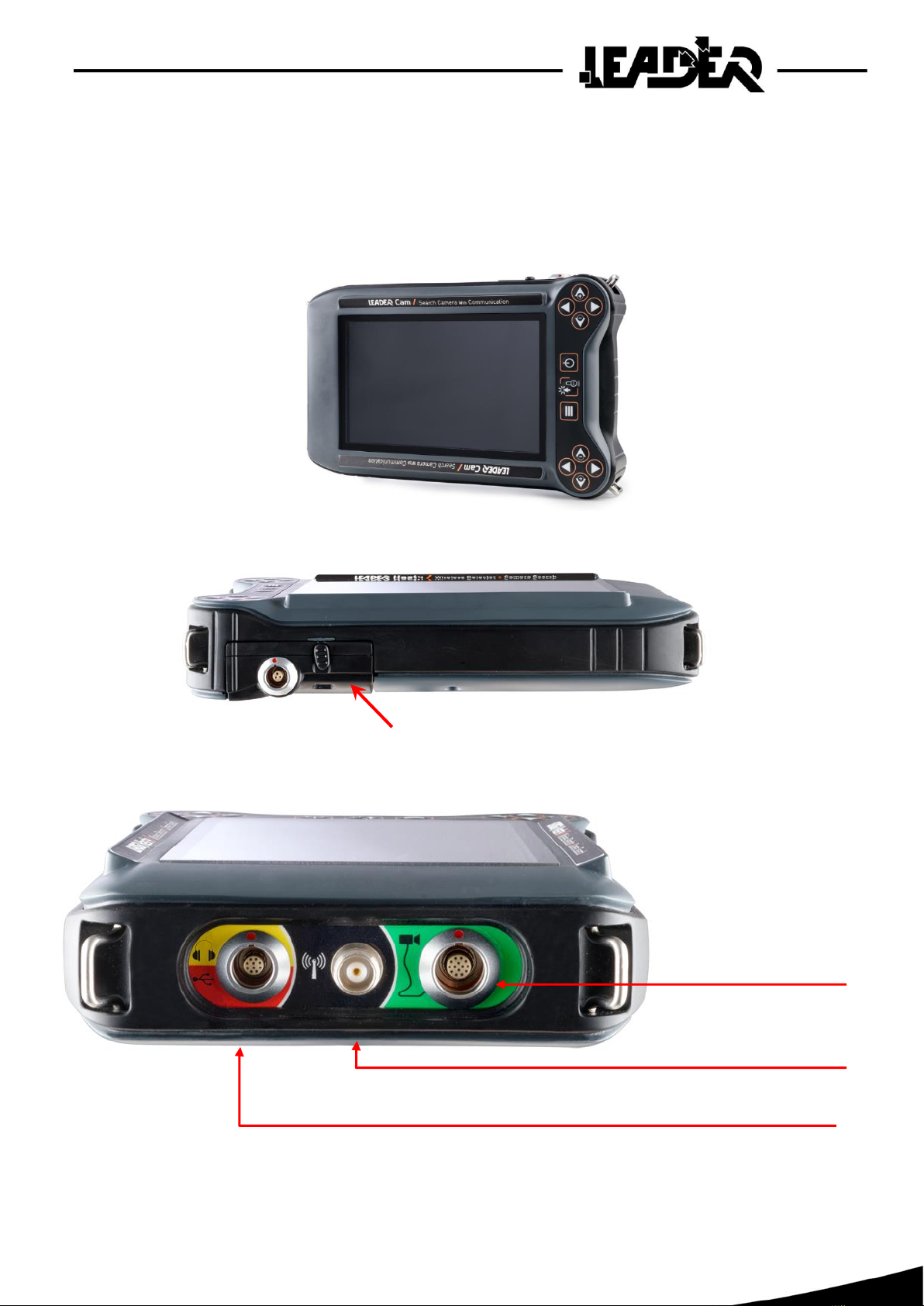
2.2. CONTROL BOX DESCRIPTION..............................................................................................................................5
2.3. KEYBOARD DESCRIPTION....................................................................................................................................6
3. USER INSTRUCTIONS......................................................................................................................7
3.1. POWER SUPPLY.......................................................................................................................................................7
3.2. REEL...........................................................................................................................................................................8
3.3. AUDIO HEADESET DESCRIPTION........................................................................................................................9
3.4. FUNCTIONS DESCRIPTION..................................................................................................................................10
3.5. Using the sun shield ..................................................................................................................................................11
4. SEARCH CAMERA MODE .............................................................................................................12
4.1. Using the main functions...........................................................................................................................................12
4.2. Camera direction function.........................................................................................................................................12
4.3. Reel end lighting intensity function...........................................................................................................................13
4.4. Push to Talk function (Communicating with the victim) ..........................................................................................13
5. Menu: Description of the Search camera mode icons........................................................................14
5.1. Zoom function...........................................................................................................................................................15
5.2. Image rotation function .............................................................................................................................................16
5.3. Photo / video recording functions..............................................................................................................................17
5.4. Picture taking function ..............................................................................................................................................18
5.5. Video recording function...........................................................................................................................................19
5.6. Photo / video viewing function..................................................................................................................................21
5.7. Right hand / left hand function..................................................................................................................................23
5.8. Screen brightness function ........................................................................................................................................23
5.9. Audio headset function..............................................................................................................................................24
5.10. Loud speaker function...............................................................................................................................................24
6. TROUBLESHOOTING.....................................................................................................................25
7. WARRANTY.....................................................................................................................................26

2
1. INTRODUCTION
The LEADER CAM R90 is used for rescue operations to see and communicate with victims.
These two devices have been designed to carry out a precise visual location of victims in confined
spaces, to dialogue with them and assess their need for help and rescue.
• Read the instructions carefully before using the product.
• The device should not be dropped or suffer shocks.
• Do not disassemble the product as this will invalid the warranty.
Do not attempt to repair the product or replace parts (except when this manual provides
specific instructions to do so). Refer all servicing to your distributor, or at Leader maintenance
service.

3
1.1.General functions
FUNCTIONS
IN SEARCH CMERA
MODE
Digital x 2 zoom
Yes
Audio headset volume control
Yes
Microphone volume control
Yes
Push to Talk
Yes
Screen brightness control
Yes
Left and right handed user
Yes
Image rotation top (0°) bottom (180°)
Yes
Battery charge level indication
Yes
Picture taking
Yes
Video recording (with no sound)
Yes
Audio recording (recording of sounds on the
communications boom)
Yes
Photo and video gallery to view recordings
Yes
1.2.Detailed technical specifications
Refer to product data sheet available on our website at www.leader-group.eu.

4
2. LEADER CAM R90 DESCRIPTION
2.1.CONTENTS
▪1 watertight and shock proof transport case.
▪1 control box with screen and keyboard and fixing straps (shoulder and hand strap).
▪1 90m (300ft) long cable on a reel with a pivoting camera with lighting, microphone
and loud-speaker module.
▪1 stereo anti-noise headset with microphone.
▪1 rechargeable battery pack.
▪1 battery pack for 10 AAA batteries (batteries not included).
▪1 charger block 100/240V 50/60Hz.
▪1 set of international adapters.
▪4 yellow caps used to make the tip of the camera watertight.
Available options:
▪1 stereo noise reducing headset with microphone and suitable connectors.
▪Extra battery pack.
▪Cable extension 90 m or 300 ft long connectible for visual searches up to 180 m or 600 ft.

5
2.2.CONTROL BOX DESCRIPTION
The control box is composed of a 7 inch TFT colour 16/9 high brightness screen.
It also has a keyboard used for multiple settings but also to scroll through the different menus.
Battery pack
Aerial connector
(function not available)
Boom
connector
USB Connector
(audio function not available)

6
2.3.KEYBOARD DESCRIPTION
The keyboard has photo luminescent keys for better visibility in the dark.
The keyboard is reversible for use by a right handed or left handed operator.
To switch from one to the other, the corresponding function must be selected.
"Right hander mode" view:
Duplicate keys
- The rescuer can use them depending on
the position
- Used by an instructor during training to
explain operation
-Functional for a left hander
when the "right/left hand"
function is set to
"left hander". The keys are all
reversed, as well as
the picture display and the
menus on the screen
Keys + and –:
- to control the brightness of the lighting
on the camera head
- to scroll up and down in the menus
- to make settings in the submenus.
Right / left keys:
- to control the direction of the pivoting
camera head.
- to make settings/selections in the sub-
menus.
ON/OFF Key
Used to power on the control box by
pressing it once. To switch off, press for 2
seconds.
Menu key
Used to display and hide the available
functions.
Triple use key:
- Validation: Used to select/validate the
menu functions
- Push-To-Talk: In camera mode, pressing
the key down continuously allows to talk to
the victim
- Photo/Video: take a picture, start and
stop video recording in the Picture/Video
functions

7
3. USER INSTRUCTIONS
3.1.POWER SUPPLY
The LEADER Cam RD90 is delivered with a lithium polymer battery pack which is inserted into the back
of the control box.
The battery pack is recharged SEPARATELY from the control box.
Charging can be carried out at between 0°C and 45°C (maximum temperature) using
the supplied charger.
During charging, a LED located on the charger provides the following indications:
▪Green: battery charged or battery not connected to the charger.
▪Red: battery charging.
During operations, if the battery pack is run down, the user can either use another battery pack
(supplied as an option D11.04.351), or the backup battery pack as a replacement for the initial battery
pack. The backup battery pack requires 10 AAA batteries (not provided).
The battery pack can ONLY be charged using the supplied charger block. It can be used with
100/240VAC - 50/60Hz
The international adapters can be used to recharge the battery pack on all US, Australian, European,
and UK power outlets.
Once the appliance is powered on, if the camera or at least one seismic sensor is turned on,
an icon showing the battery pack charge level remains displayed on the top right of the screen.
5 icons to show the control box battery pack
charge level
Icon displayed when the backup
battery pack is being used
Mains adapters
Charger block
Battery pack

8
3.2. REEL
The reel is equipped with 90 m (300ft) long cable. It is equipped with a rotating video camera
with integral lighting and a microphone/speaker module. The 47mm diameter head is small enough
to be inserted into core cutter holes. The microphone is sensitive enough to pick up whispering.
The video cameras 90° viewing angle, and the fact that it can rotate through 160° means that
the equipment has an observation angle of 250°, with no blind spots. In option an extension
of 90 m (300ft) cable on reel is available for visual research until 180m (600ft).
NB: Over a 180 m (600ft) length only the video is available. The communication between the rescuer
and the victim is not possible with two reel.
Setting-up:
▪Connect the reel to the consol.
▪Connect the headset(s) to the consol.
▪Turn the control panel on by pressing the ‘on/off’ button.
▪To turn the consol off, press the ‘on/off’ button for 2 seconds.
▪When the consol is turned off, the camera resets itself in line with the axis so as to facilitate
stowing it in the case.
▪The default position for the gains is 'middle', except for the lighting, which is off.
The camera head is protected both by a watertight plastic sleeve over its entire length and by a non scratch
sapphire lens on its façade. The camera head can be made watertight: To do this a cap must be fitted onto
the microphone/speaker.

9
The metal plate of the the microphone/speaker needs to be unscrewed and must be replaced
by the waterproof cap.
This system makes it possible to search under water to a maximum depth of 2 m or 6 ft.
3.3.AUDIO HEADESET DESCRIPTION
The LEADER Cam R90 has a noise reducing headset with a microphone. It is equipped with a neck
band, an omnidirectional microphone, 2 300 ohm earpieces and a connection cable (length 2 m)
with a specific watertight connector once connected to the control box.
The audio headset is used to:
•communicate with the victim in search camera mode
•to listen to the wireless sensors in seismic mode
A second optional headset can be connected to the control box using a Y connector allowing two
headsets to be connected to the me connector.

10
3.4. FUNCTIONS DESCRIPTION
Powering ON
The device is powered on by pressing the ON/OFF key once.
On powering on, a first screen is displayed.
A loading screen quickly follows. On the bottom left of the screen it shows the version of the device
software and on the bottom right the serial number.
If the reel is not connected, the screen shows the following icons "camera not connected".
The device will remain on this screen for 5 minutes before powering off automatically
if no action is detected.
Turning off the control box
To turn off the control box, press the ON/OFF key for 2 seconds.
A message is displayed indicating that the battery should not be removed until
the message disappears: "Please, DO NOT REMOVE the battery pack while this
message is displayed"
Please follow these instructions so that the software closes correctly and to guarantee
it operates correctly the next time it is launched.
LEADER Cam version 1.1.1
42587369

11
3.5.Using the sun shield
In bright light, the sun shield is used to place the screen in a dark area
to be able to see it better.
To hold the sun shield on the control box it must be correctly positioned
on the face on the forms designed to this effect. The red line shows
the position.
The wide elastics are used to ft it quickly and easily.
It is stored flat for easier transport. An elastic on its side is used to keep it flat and fix it to the control
box. By placing it on the screen face, it protects the screen when moving around when the search
device is not in use.
It has small inner pockets to store an SD photo card for example.

12
4. SEARCH CAMERA MODE
4.1.Using the main functions
The search camera mode and its menu appear when the boom is connected. Pressing the menu button
accesses the different function .
Up to ten icons can then be selected. The "▲" and "▼" navigation keys are used to select the required
function. Pressing the validation key gives access to the required function. Pressing the menu key
again exits the menu window and returns to the main screen.
4.2.Camera direction function
The right/left camera orientation is achieved using the ► or ◄ keys without using the menu.
When the camera rotates, an icon is displayed on the screen showing its position.
The camera head can be mechanically oriented 85° to the right and 85° to the left (170° total).
The directional camera and head provide a 260° field of vision without any blind spots.
•Pressing keys ► or ◄ first displays the icon and shows the camera position.
•Pressing the ► or ◄ key again moves the camera to the right or left depending on the key
that is used. On the screen, the position icon shows 9 increments. The key must be pressed several
times to pass from one increment to the next. Keeping the key pressed down permanently rotates
the camera continuously.
•The icon disappears after 2 seconds if there is no action on the ► or ◄ keys.
Example of right rotation.
The blue axis shows the direction.
The orange zones show the field of vision.

13
4.3.Reel end lighting intensity function
The intensity of the lighting at the tip of the boom is controlled directly using the ▼ and▲ keys without
using the menu. When modulating the lighting, an icon is displayed on the screen showing the intensity
level:
•8 lighting intensity levels can be selected.
•Pressing the ▼ or▲ keys displays the icon and checks the lighting intensity.
•The lighting only changes when the ► or ◄ keys are pressed a second time.
•Continuously pressing a key makes it possible to increase or decrease the lighting intensity
continuously.
•The icon disappears after 2 seconds if there is no action on the ► or ◄ keys.
4.4.Push to Talk function (Communicating with the victim)
By default, listening to the victim has priority. Transmission from the rescuer
to the victim is established by keeping the Push-to-talk key pressed down
(press to talk). Transmission to the victim does not allow the victim to be listened
to while the Push-to-talk button is being pressed.
A second headset can be connected (supplied as an option). The second headset has the same
functions as the first.
If the Push-to-Talk button is not pressed, both headsets communicate with each other without
the victim being able to hear.
Example of the
"lighting" icon

14
5. Menu: Description of the Search camera mode icons
•The "picture zoom" function is used for digital enlargement. The displayed image
can be enlarged twice (Digital zoom x2).
•The "picture rotate" function is used to rotate an image by 0°, and 180°
on the screen.
•The "video" function is used to record videos on the micro SD card.
•The "picture" function is used to take shots and record them on the micro SD
card.
•The "left/right hand" function is used to allow the control box to be used by a left
handed or right handed operator by reversing the image, function display on
the screen, and the keyboard operation.
•The "brightness" function is used to set the screen brightness.
•The "headset" function is used to control the headset volume when listening
to the victim.
•The "speaker" function is used to control the volume of the loud speaker at the tip
of the boom. It is used for communications between the rescuer and the victim.
•The "gallery" function gives access to the video recordings and pictures taken
using the "video" and "picture" functions to view them on the screen.
The "picture zoom", "picture rotate", "picture", "video" and "left/right hand"
functions can be used at the same time.
Once the functions have been selected, miniature icons appear at the top right
of the screen. They remain on the screen permanently until they are deactivated.

15
5.1.Zoom function
The "picture zoom" function is used for digital enlargement. The displayed image can be enlarged
twice (Digital zoom x2).
•To zoom: select the "picture zoom" function from the menu then press the validation key. Once on
the sub-menu, select "zoom in" then press the validation key to activate the function and enlarge
the picture by 2.
A magnifying
glass icon
appears at the top
right of the screen
to indicate that the
image has
been enlarged
•To zoom out: select the "picture zoom" function from the menu then press the validation key.
Once on the sub-menu, select "zoom out" then press the validation key to activate the function and
display the picture at its normal x1 size.
The magnifying
glass icon then
disappears from
the top right of
the screen.

16
5.2.Image rotation function
The "picture rotate" function is used to rotate an image by 0°, and 180° on the screen.
•By default the image is displayed the right way up at 0°.
•To rotate by 180°, select the "picture rotate" function from the menu then press the validation key.
Once on the sub-menu, use the keyboard ▼ key directly. The image rotates immediately.
An icon appears at the top right of the screen to indicate in what direction the image is now
positioned. The middle tip of the triangle shows the top of the image.
•To place the image back at 0°, press the ▲ key directly if you are still on the sub-menu. Otherwise
select the "picture rotation" function from the menu then press the validation key.
Once on the sub-menu, use the keyboard ▲key directly. The image rotates immediately.

17
5.3.Photo / video recording functions
The LEADER Cam R90 has a picture taking and a video recording function. These two functions
are only available if a microSD backup card is in the control box reader.
A Class 10 4Go card is inserted in the reader of each delivered control box.
The number of pictures and recorded video times vary depending on the number of pictures and videos
taken as the intervention progresses. However, as an indication:
•If only pictures are taken (with 1Go): 1000 pictures can be saved.
•If only videos are recorded (with 1Go): about 1 hours of video can be saved.
The microSD card reader is located under a flap behind the control box. To access it, remove
the battery pack.
The "picture" (photos), "video" and "gallery" (viewing pictures/videos) are only active
when a microSD card is present in the control box.
Otherwise the icons for these functions are greyed out.
MicroSD card
Access flap
MicroSD card reader
Table of contents