TETRIX Tele-Op User manual

Tele-Op Module Activity 1 – Tele-Op Commands
Parts Needed
• PRIZM controller
• Tele-Op module
• PS4 DUALSHOCK 4 gaming controller
• TETRIX MAX 12-volt battery
• PRIZM controller on/off switch
• Powerpole extension cable
• Daisy-chain data cable
• USB cable
Hardware Connections
1. Connect the TETRIX MAX 12-volt battery to the PRIZM on/o switch.
2. Connect the PRIZM on/o switch to one of the battery connection
ports on PRIZM.
3. Connect one end of the Powerpole extension cable to the other battery
connection port on PRIZM. Connect the other end of the Powerpole
extension cable to the battery connection port on the Tele-Op module.
4. Connect one end of the daisy-chain data cable to PRIZM’s expansion
port (labeled EXP). Connect the other end of the daisy-chain data cable
to the I2C port on the Tele-Op module.
Overview
This activity will introduce you to the TETRIX® Tele-Op Control Module and how it
connects to the PRIZM® controller. It will also help you to become familiar with the
functions and commands for using the Tele-Op module paired with a
PS4 DUALSHOCK 4 gaming controller.
TETRIX Tele-Op Control Module Activity 1 1

Bluetooth Connections
1. Make sure all devices that your PS4 controller has previously been
paired with are o. This enables the PS4 controller to search for and
connect to your Tele-Op module.
2. Make sure the PS4 controller is o.
3. Plug the Bluetooth dongle into Tele-Op module’s USB port.
4. Turn on the PRIZM controller. The PRIZM controller and the Tele-Op
module should both have a blue LED that lights up, indicating they
have power. You should also notice a green ashing LED on the Tele-
Op module, indicating that the Bluetooth dongle is compatible. If
you do not see a green ashing light, then no Bluetooth dongle is
connected or the dongle is not compatible with the Tele-Op module.
Refer to the Tele-Op technical guide for more information on Bluetooth
compatibility.
5. To pair the PS4 controller with the Bluetooth dongle, the controller
must be put into discovery mode. On the PS4 controller, hold down the
Share and the Power button at the same time for about ve seconds
until you see the controller’s light bar ash white in a rapid pattern. The
controller is now in discovery mode.
6. Press the black button on the Tele-Op module. The green LED on the
Tele-Op module should remain on and stop ashing. Also, the light bar
on the game controller should be a solid green color to indicate the
controller is paired and ready to be used to control the Tele-Op module.
7. After the PS4 controller has been paired with the Bluetooth dongle in
the Tele-Op module, you don’t need to go through this process again
unless you want to pair a dierent device or Bluetooth dongle. Simply
turn on PRIZM and the Tele-Op module and then press the Power
button on the PS4 controller. The controller will automatically connect
to the Bluetooth dongle in the Tele-Op module.
Note: When you connect the PS4
controller to the Tele-Op module,
the game controller pairs with the
Bluetooth dongle that is inserted
into the Tele-Op module’s USB
port. If you remove the dongle
from one Tele-Op module and
plug it into another, the game
controller can now be used
to control the second Tele-Op
module.
Note: When you turn off power
to PRIZM and the Tele-Op
module, the PS4 controller will
automatically turn off after about
10 seconds.
Share Power
2TETRIX Tele-Op Control Module Activity 1

Opening the Sketch
On your computer, open the Arduino Software (IDE). The sketch for this activity is
stored with the examples that come with the Tele-Op library. To open the sketch,
select File > Examples > TETRIX_TeleOp > PS4_Examples > PS4_Controller_
Example. A new sketch window will open with the example sketch.
This sketch has several sections. At the beginning, block comments are used to
describe the example and how to pair the PS4 controller. Following this section is
a listing of all the functions and commands that are included in the Tele-Op library
along with descriptions of what they do and possible values that can be returned by
the functions depending on the controller’s status.
After the block comments at the beginning are the first lines of actual code. Notice
that the Tele-Op module has its own library that must be included along with the
PRIZM library. Following these initial lines of code is the void setup() section. This
section sets up the serial monitor, initializes PRIZM, and sets the dead zones for the
joysticks on the PS4 controller. We’ll talk more about dead zones in the Hacking the
Code section of this activity.
In the main loop, there is one active command. The ps4.getPS4() command gets the
status of all the buttons and joysticks on the PS4 controller at one time as one data
package. This command needs to be frequently repeated so that as the user uses the
controller, the status of what buttons are pressed gets communicated to PRIZM.
Notice that the other commands in the main loop have been commented out. In
other words, they have been turned into comments by adding “//” before each
line. Each of these commented-out commands calls a function. The functions are
listed after the main loop. Each function displays information in the serial monitor
related to using certain Tele-Op commands. Because the function calls have been
commented out, if you were to run the sketch as is, nothing would happen other
than executing the command to get the button and joystick statuses of the PS4.
In order for the sketch to actually do something, one of the functions needs to be
turned on by uncommenting it. In the main loop, find the command that calls the
Status() function.
Remove the “//”at the beginning of the command to change the command from a
comment to a function call. Notice how the text changes from gray to black. With
this command uncommented, the main loop will continuously call the Status()
function, which displays the PS4 connection status in the serial monitor.
TETRIX Tele-Op Control Module Activity 1 3

Executing the Code
1. Connect the USB cable to a USB port on your computer or device.
Connect the other end of the cable to the USB port on PRIZM.
2. Make sure PRIZM is turned on and the PS4 controller is paired with the
Tele-Op Module. If it isn't, follow the steps in the Bluetooth Connections
section.
3. In the Arduino Software (IDE), make sure the correct COM port is
selected to communicate with PRIZM. Go to Tools > Port and then
select the correct COM port.
4. In the software window, click the Upload button to upload the sketch.
After the sketch has been uploaded, leave the USB cable connected so
that you can use the serial monitor.
5. Open the serial monitor by selecting Tools > Serial Monitor. In the
lower-right corner of the serial monitor window, make sure the baud
rate is set to 115200 in the drop-down window.
6. Start the program by pressing the green Start button on PRIZM. Pay
attention to the message displayed on the serial monitor. If the PS4
controller is not connected, the connection status will be 0. If the
controller is connected, the status should be 1.
7. Try turning o the PRIZM controller. Wait for the PS4 controller to turn
o (about 10 seconds). Close the serial monitor in the Arduino Software
(IDE). Then turn PRIZM back on and wait for the green LED next to
PRIZM’s red Stop/Reset button to turn on. Reopen the serial monitor in
the Arduino Software (IDE). Run the program again by pressing PRIZM’s
Start button. The serial monitor should display a connection status
of 0. Now press the Power button on the PS4 controller. As soon as it
connects to the Tele-Op module, the serial monitor should display a
connection status of 1.
8. In the Arduino Software (IDE), nd the void Status() function. Notice
that the command that returns the connection status of the PS4
controller is ps4.Connected.
9. Return to the main loop and turn o the Status() function call by
adding “//” back to the beginning of the command line.
Note: The Tele-Op module has a
USB port that is used to flash its
firmware. This USB port should not
be used when uploading sketches.
Make sure you use the USB port
on PRIZM. Uploading a sketch to
the Tele-Op module will overwrite
its firmware, making it unusable
until it can have its firmware
flashed again.
4TETRIX Tele-Op Control Module Activity 1

Moving Forward
Explore the other functions by uncommenting each function, one at a time, and
uploading the sketch to PRIZM. As the sketch runs, experiment with the PS4
controller while observing the output in the serial monitor.
Range()
This function determines if the PS4 controller is in Bluetooth range of the Tele-Op
module. The command ps4.inRange will return 1 if the controller is in range and 0
if the controller is out of range. In the main loop, uncomment the Range() function
call to run this function.
TeleOpReset()
This function forces the Tele-Op module to reset itself. The command for resetting
the Tele-Op module is ps4.resetTeleOp(). In this sketch, when this command is
executed, the program enters a never-ending loop to keep from endlessly resetting
the Tele-Op module. The ps4.resetTeleOp() command could be used to pass
control from one PS4 controller to another without restarting the program on
PRIZM. For example, if a robotics competition required two drivers each with his
or her own controller, you’d pair both controllers but power on only one of them.
When it was time to pass off control, you could do a remote reset of the Tele-Op
module, power off the first controller, and power on the second controller to take
control of the robot, all without ever having to restart the program.
TouchXY()
This function returns the x- and y-coordinates of the last touched area of the
PS4’s touch pad. As you drag your finger across the touch pad from left to right,
you should see the x-coordinate increase from 0 to 1920 in the serial monitor. In
the same way, as you drag your finger down from top to bottom, you should see
the y-coordinate increase from 0 to 941. The commands for returning the x- and
y-coordinates from the touch pad are ps4.Touchpad(TOUCHX) and
ps4.Touchpad(TOUCHY).
TETRIX Tele-Op Control Module Activity 1 5

ControllerAngle()
The PS4 controller has a built-in gyroscope that it uses to measure the controller’s
tilt. The tilt measurements can be read by PRIZM and used to control elements such
as servos and motors. In the ControllerAngle() function of the sketch, the PS4
controller’s pitch (forward and back angle) and roll (side-to-side angle) is output to
the serial monitor. The commands ps4.Angle(PITCH) and ps4.Angle(ROLL) each
return a value of 0 to 360 degrees. When the controller is level on flat surface, the
PITCH and ROLL of the controller should be about 180 degrees each. This value
increases as you tilt the controller forward (pitch) or to the right (roll) and decreases
as you tilt the controller back or to the left.
There are four other commands associated with the controller’s pitch and roll
measurements:
• ps4.Motor(PITCH) – Maps the controller’s forward or back tilt to a motor’s
range of -100 to 100 percent power. When the controller is level, a value of 0
is returned.
• ps4.Motor(ROLL) – Maps the controller’s side-to-side tilt to a motor’s range
of -100 to 100 percent power. When the controller is level, a value of 0 is
returned.
• ps4.Servo(PITCH) – Maps the controller’s forward or back tilt to a servo’s
range of 0 to 180 degrees. When the controller is level, a value of 90 degrees
is returned.
• ps4.Servo(ROLL) – Maps the controller’s side-to-side tilt to a servo’s range
of 0 to 180 degrees. When the controller is level, a value of 90 degrees is
returned.
Sticks()
Each joystick on the PS4 controller has two analog values associated with it that
range from 0 to 255. The xvalue indicates its horizontal position and the yvalue
indicates its vertical position. The Sticks() function returns the xand yvalues of
both joysticks. The command that returns the joystick position is
ps4.Stick(CONTROL)where CONTROL can be any of the following:
• LX – left joystick xposition (side to side)
• LY – left joystick yposition (up and down)
• RX – right joystick xposition (side to side)
• RY – right joystick yposition (up and down)
For each joystick’s horizontal position, a value of 0 is returned when the joystick is
all the way to the left, and 255 is returned when the joystick is all the way to the
right. For the vertical position, 0 is returned when the joystick is all the way down,
and 255 is returned when the joystick is all the way up. When the joysticks are
centered, the xand ypositions should be about 128.
Note: Depending on your
controller, you might notice that
your joysticks do not naturally
center at exactly 128 for their x
and ypositions. This is normal and
is why the dead zone command
can be very useful when using
the sticks to control motors and
servos.
255
2550
0
x
y
6TETRIX Tele-Op Control Module Activity 1

Buttons()
This function shows the button press status of a single PS4 controller button. The
command for determining the press status of a button is ps4.Button(CONTROL).
Two types of values can be returned from this command depending on how the
function is used. All the buttons listed below return a digital Boolean value of either
0 (not pressed) or 1 (pressed) depending on whether the button is pressed or not.
However, the L2 and R2 buttons can also be used as trigger buttons that return an
analog value of 0 to 255 depending on how far the button is pressed. The same
command is used to return analog values of the trigger buttons except that a T
must be added to designate the buttons as analog: ps4.Button(L2T) or
ps4.Button(R2T). The L2 and R2 buttons are the only buttons that can return
analog values. When you first open the example sketch, the function returns the
status of the triangle button. You can change which button is output to the serial
monitor by changing the word TRIANGLE in the command to any of the buttons in
the list or by using L2T and R2T for the analog trigger buttons.
MoveMotor()
Although there are no motors connected to PRIZM for this activity, this function
shows how a motor can be controlled using a PS4 controller. This function outputs
a value of -100 to 100 to the serial monitor based on the left joystick’s yvalue. When
the left joystick is centered, a value of 0 is output to the serial monitor. This would
indicate a motor power of 0 and the motor would not turn. If you push the left
joystick up, the value increases to a maximum of 100 when the joystick is all the
way up. This would indicate a motor power of 100 percent. If you pull the joystick all
the way down, the value decreases until it reaches -100. The command for getting
the joystick position and mapping it to the motor range (-100 to 100) is
ps4.Motor(CONTROL) where CONTROL can be any of the following:
• LX – left joystick xposition (side to side)
• LY – left joystick yposition (up and down)
• RX – right joystick xposition (side to side)
• RY – right joystick yposition (up and down)
• L2T – L2 trigger button
• R2T – R2 trigger button
• PITCH – rotating the controller forward or back using the PS4 controller’s
internal gyroscope
• ROLL – rotating the controller side to side using the PS4’s controller’s internal
gyroscope
These are the only controls that work for the ps4.Motor(CONTROL)command
because these are the PS4 button and joystick controls that return analog values
based on their position.
• L1
• L2
• L3
• R1
• R2
• R3
• UP
• DOWN
• RIGHT
• LEFT
• TRIANGLE
• CROSS
• CIRCLE
• SQUARE
• SHARE
• OPTIONS
• POWER
• TOUCH
TETRIX Tele-Op Control Module Activity 1 7

MoveServo()
Although there are no servos attached to PRIZM for this activity, this function shows
how a servo could be controlled using the PS4 controller. This function outputs
a value of 0 to 180 to the serial monitor depending on the yvalue of the right
joystick. When the joystick is centered, a value of 90 is output to the serial monitor.
If you push the right joystick up, the value increases until it reaches 180 when the
joystick is all the way up. If you pull the joystick down, the output value decreases
until it reaches 0. The command for getting the joystick position and mapping it to
the servo range (0 to 180) is ps4.Servo(CONTROL)where CONTROL can be any of
the following:
• LX – left joystick xposition (side to side)
• LY – left joystick yposition (up and down)
• RX – right joystick xposition (side to side)
• RY – right joystick yposition (up and down)
• L2T – L2 trigger button
• R2T – R2 trigger button
• PITCH – rotating the controller forward or back using the PS4 controller’s
internal gyroscope
• ROLL – rotating the controller side to side using the PS4’s controller’s internal
gyroscope
These are the only controls that work for the ps4.Servo(CONTROL)command
because these are the PS4 button and joystick controls that return analog values
based on their position.
Rumble()
This function toggles on the rumble motors in the PS4 controller. When this
function is called, the controller will vibrate at the slow speed for 1 second, then
at the fast speed for 1 second, and then stops for 1 second. The command for
changing the rumble motor’s status is ps4.setRumble(STATUS)where STATUS
can be SLOW, FAST, or STOP. One use of the rumble motors would be to have the
controller vibrate when it is out of range of the Tele-Op module.
LEDcolor()
This function changes the LED color of the PS4 controller's light bar. The light
bar will change from red to blue to yellow to green every 500 milliseconds. The
command for changing the light bar color is ps4.setLED(COLOR)where COLOR can
be RED, BLUE, YELLOW, or GREEN. Examples of when you might want to change
the light bar color is to distinguish your controller from others, to indicate different
modes of operation, to signal errors, and to represent different sensor data values.
8TETRIX Tele-Op Control Module Activity 1

buttonsGroup1()
Button combos are common in the gaming world because they enable you to
perform special moves or take certain actions when certain buttons are pressed at
the same time. The Tele-Op module has some easy-to-use commands that can be
programmed to do certain actions or tasks when different button combinations are
pressed on the PS4 controller. The buttons on the PS4 controller are divided into
two groups.
The ps4.buttons_1 command will return a byte value that represents the Boolean
states of the buttons in Group 1. In other words, this command returns an assigned
value depending on which buttons are pressed from Group 1. Each combination of
buttons has a unique assigned value.
In this sketch, the buttonsGroup1() function outputs the byte value for whatever
button combination is pressed on the PS4 controller. It also outputs the byte value
as a binary number where each digit represents the on/off status of a particular
button. For example, if you press all the Group 1 buttons at the same time, the
function will output a decimal value of 255 and a binary value of 11111111. In the
binary number, each 1 represents a different button that is pressed. If you were to
keep holding all the buttons down but release the L2 button, the function would
output a decimal number of 254 and a binary value of 11111110, indicating that
the L2 button is not pressed.
There are too many button combinations to list them all here. However, you can
use this sketch any time you are programming with the Tele-Op module to quickly
identify the unique byte value of any button combination.
Group 1
• L1
• L2
• R1
• R2
• Cross
• Circle
• Triangle
• Square
Group 2
• Up
• Down
• Left
• Right
• L3
• R3
• Share
• Options
Binary value when all buttons in Group 1 are pressed.
Note: A practical application of
using button groups is shown in
Tele-Op Activity 2. In this activity,
button groups are used to change
the speed of a robot from normal
speed to either crawl or turbo
speed.
TETRIX Tele-Op Control Module Activity 1 9

buttonsGroup2()
This function works exactly like the buttonsGroup1() function except that it
returns the status of the buttons in Group 2 (Up, Down, Left, Right, L3, R3, Share,
and Options). The command for returning the status of the Group 2 buttons is
ps4.buttons_2.
Notice that because of the way the direction buttons work, it is impossible to hold
all four of them down at the same time.
Hacking the Code
Attach a standard servo and a motor to the PRIZM. Using the example sketch as
reference, write a new sketch to control the servo using these PS4 controls:
• L2 trigger button
• Left joystick
• Touch pad’s xposition
• Roll from the PS4 controller’s gyroscope
Add commands to control the motor using these controls:
• R2 trigger button
• Right joystick
• Touch pad’s yposition
• Pitch from the PS4 controller’s gyroscope
In the void setup() section, include the commands:
Experiment with changing the value of the dead zones from 10 to 0. How does this
affect the servo or motor? Then change the value to 50. Do you notice a difference
in how the servo and motor behave?
Dead Zones
Precisely controlling servos and motors using joysticks can be difficult sometimes
because the joysticks don’t always return to the exact center. This might cause your
servo to not return to its center position or your motor to continue to slowly spin
when the joysticks are released. By setting a dead zone, you identify the size of
an area for the joystick’s x- and y-axis that is considered neutral. When the joystick
returns to this neutral dead zone area, the joystick is considered to be centered.
Setting a higher dead zone value gives you a bigger neutral area but reduces the
sensitivity of the joystick outside the dead zone. On the other hand, a small dead
zone gives you more precise sensitivity but reduces the neutral area of the joystick.
You’ll need to experiment with your controller to find the right balance of joystick
sensitivity and dead zone.
Note: When the binary values of a
button combination are displayed,
the leading zeros are left off.
This is why when the L1 button
is pressed by itself, the function
outputs 1 instead of 00000001.
However, if you hold down the
Triangle button, all eight digits will
appear, and it is easier to see how
each digit represents a different
button. For Group 2, hold down
the Options button to see all eight
digits.
Binary value when only the Options button is pressed.
10 TETRIX Tele-Op Control Module Activity 1
Other manuals for Tele-Op
1
Table of contents
Popular Control Unit manuals by other brands
Nordson EFD
Nordson EFD 754V-SS Maintenance & Parts Guide

ESD
ESD CAN-USB/3-FD Hardware manual

Niko
Niko 10-535-01 manual
Baumuller
Baumuller b maXX BM4-O-CAN-03 Instruction handbook
National Instruments
National Instruments NI-9244 User manual and specifications
Solid Technologies
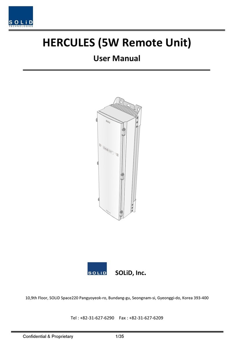
Solid Technologies HERCULES user manual
