User's Guide
SLUUB55–September 2014
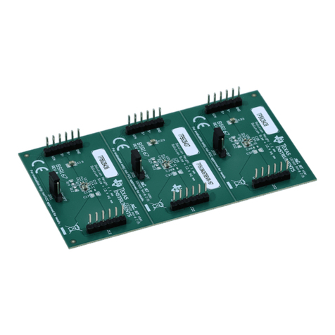
bq51025 Evaluation Module (PWR649)
The bq51025EVM-649 (PWR649) wireless power receiver evaluation kit (EVM) from TI is a high
performance, easy-to-use development kit for the design of wireless power solutions. It helps designers
evaluate the operation and performance of the bq51025 IC, a secondary-side receiver device for wireless
power transfer applications. The bq51025 device is a fully-contained, wireless power receiver capable of
operating in WPC v1.1 protocol which allows a wireless power system to deliver up to 5 W to the system
when used with a Qi inductive transmitter. When paired with the bq500215EVM-648 (PWR648), the
bq51025 is capable of delivering up to 10 W to the system. The bq51025 device provides a single device
power conversion (rectification and regulation) as well as the digital control and communication for WPC
specification. The kit enables designers to speed up the development of their end-applications.
Contents
1 Introduction ................................................................................................................... 2
2 Considerations with this EVM.............................................................................................. 3
3 Modifications.................................................................................................................. 4
4 Recommended Operating Conditions..................................................................................... 4
5 Equipment and EVM Setup................................................................................................. 5
5.1 Schematic............................................................................................................ 5
5.2 Recommended Test Equipment .................................................................................. 6
5.3 Equipment Setup.................................................................................................... 6
5.4 Connector Descriptions ............................................................................................ 7
5.5 Jumpers and Switches............................................................................................. 7
5.6 Test Point Descriptions ............................................................................................ 8
5.7 Pin Description of the IC .......................................................................................... 9
6 Test Procedure ............................................................................................................. 10
6.1 Definition............................................................................................................ 10
6.2 Procedure .......................................................................................................... 10
7 Test Results................................................................................................................. 14
7.1 Steady-State Operation with the bq24261 Charger .......................................................... 14
7.2 Load Step .......................................................................................................... 15
7.3 Start Up............................................................................................................. 16
7.4 Efficiency Data..................................................................................................... 17
7.5 Adapter Insertion and Removal ................................................................................. 17
7.6 Thermal Performance............................................................................................. 18
8 Layout and Bill of Material ................................................................................................ 19
8.1 bq51025 Traces .................................................................................................. 19
8.2 Layout Guidelines ................................................................................................. 19
8.3 Printed-Circuit Board Layout Example ......................................................................... 19
8.4 bq51025EVM-649 Layout ........................................................................................ 21
8.5 Bill of Materials (BOM)............................................................................................ 24
List of Figures
1 bq51025EVM-649 Schematic .............................................................................................. 5
2 Placement of PWR649 on PWR648..................................................................................... 11
3 bq51025 in Steady State Operation with bq24261 .................................................................... 14
4 1-A Load Step .............................................................................................................. 15
5 1.4-A Load Step ........................................................................................................... 15
1
SLUUB55–September 2014 bq51025 Evaluation Module (PWR649)
Submit Documentation Feedback Copyright © 2014, Texas Instruments Incorporated
