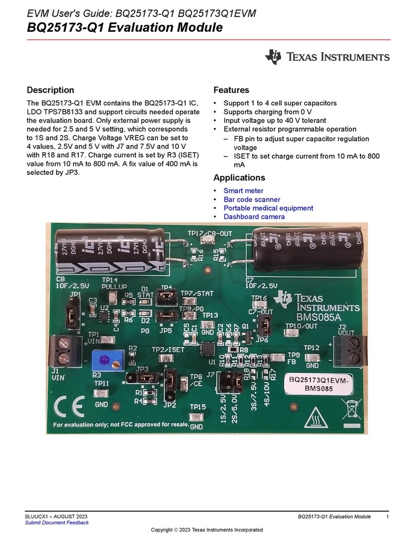
User’s Guide
DS90UB95x-Q1 Serializer Evaluation Module
Ankur Verma, Cole Macias
ABSTRACT
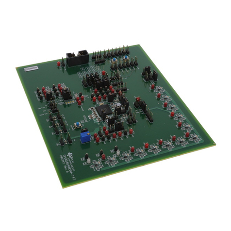
The Texas Instruments DS90UB95x-Q1EVM evaluation module (EVM) is a functional board design for
evaluating the DS90UB953-Q1 FPD-Link III serializer and the TSER953 V3Link serializer. This document
provides necessary details for the evaluation such as a brief product overview, quick-start guide, troubleshooting
section, schematics, and printed-circuit board (PCB) layout details, and bill of materials (BOM).
The DS90UB953-Q1 and TSER953 serializers represent the next generation in FPD-Link III and V3Link
serializers and are designed to support high-speed raw data sensors including 2-MP imagers at 60 fps, as
well as 4-MP, 30-fps cameras, satellite RADAR, LIDAR, and time-of-flight (ToF) sensors. The chip delivers a
4-Gbps+ forward channel and an ultra-low latency, 50-Mbps bidirectional control channel. The chip also supports
power over a single coax (PoC) or shielded twisted-pair (STP) cable and connector. The DS90UB953-Q1 and
TSER953 feature advanced data protection and diagnostic features to support ADAS, autonomous driving, and
industrial and medical imaging applications. Together with a companion deserializer, the chip delivers precise
multi-camera sensor clock and sensor synchronization. For a full list of device characteristics, refer to the
DS90UB953-Q1 and TSER953 product folders.
Table of Contents
1 Introduction.............................................................................................................................................................................3
2 Quick Start Guide....................................................................................................................................................................4
3 Troubleshooting......................................................................................................................................................................7
4 Bill of Materials..................................................................................................................................................................... 39
5 PCB Schematics................................................................................................................................................................... 43
6 Board Layout.........................................................................................................................................................................47
7 Related Documentation........................................................................................................................................................53
8 Revision History................................................................................................................................................................... 53
List of Figures
Figure 1-1. DS90UB95x-Q1EVM Top View................................................................................................................................. 3
Figure 2-1. Typical Application Block Diagram Using DS90UB953-Q1 and DS90UB954-Q1 (or variant)...................................4
Figure 2-2. DS90UB95x-Q1EVM Major Components................................................................................................................. 5
Figure 2-3. DS90UB95x-Q1EVM With Installed Jumpers........................................................................................................... 5
Figure 2-4. DS90UB954-Q1EVM (or variant) With Jumpers Highlighted.................................................................................... 6
Figure 3-1. USB2ANY..................................................................................................................................................................7
Figure 3-2. I2C Pinout of USB2ANY Connector.......................................................................................................................... 8
Figure 3-3. Launching ALP........................................................................................................................................................ 10
Figure 3-4. Initial ALP Screen....................................................................................................................................................10
Figure 3-5. Follow-Up Screen.................................................................................................................................................... 11
Figure 3-6. ALP Information Tab................................................................................................................................................12
Figure 3-7. ALP Registers Tab...................................................................................................................................................13
Figure 3-8. ALP Device ID Selected.......................................................................................................................................... 14
Figure 3-9. ALP Device ID Expanded........................................................................................................................................15
Figure 3-10. Writing to Register 0x00 by Checking Bits in ALP.................................................................................................15
Figure 3-11. ALP Scripting Tab.................................................................................................................................................. 16
Figure 3-12. Pre-Defined Scripts............................................................................................................................................... 17
Figure 3-13. Custom Button Creation Step 1.............................................................................................................................18
Figure 3-14. Custom Button Creation Step 2.............................................................................................................................18
Figure 3-15. ALP Scripting Tab..................................................................................................................................................21
www.ti.com Table of Contents
SNLU224C – SEPTEMBER 2017 – REVISED APRIL 2021
Submit Document Feedback
DS90UB95x-Q1 Serializer Evaluation Module 1
Copyright © 2021 Texas Instruments Incorporated
