Table of Contents
1 EVM Overview......................................................................................................................................................................... 4
1.1 ADS131B26Q1EVM-PDK Features................................................................................................................................... 4
1.2 ADS131B26Q1EVM-PDK Quick-Start Guide.....................................................................................................................5
2 Analog Interface......................................................................................................................................................................5
2.1 Terminal Blocks and Test Points........................................................................................................................................ 6
2.2 ADC1A and ADC1B........................................................................................................................................................... 7
2.3 ADC2A and ADC2B........................................................................................................................................................... 7
2.4 ADC3A and ADC3B........................................................................................................................................................... 8
3 Digital Interface.......................................................................................................................................................................9
3.1 Connection to the PHI Controller....................................................................................................................................... 9
3.2 Digital Header.................................................................................................................................................................. 10
3.3 Clock Options...................................................................................................................................................................10
4 Power Supplies..................................................................................................................................................................... 11
4.1 DC/DC Converter Circuit.................................................................................................................................................. 11
4.2 ADC Power Supplies........................................................................................................................................................12
4.3 Power Supply and Voltage Reference Decoupling.......................................................................................................... 12
5 ADS131B26Q1EVM-PDK Initial Setup.................................................................................................................................13
5.1 Default Jumper Settings...................................................................................................................................................13
5.2 EVM Graphical User Interface (GUI) Software Installation.............................................................................................. 14
6 ADS131B26Q1EVM-PDK Software Reference....................................................................................................................16
6.1 Global Settings for ADC Control...................................................................................................................................... 16
6.2 Register Map Configuration............................................................................................................................................. 17
6.3 Analysis Tools.................................................................................................................................................................. 19
7 ADS131B26Q1EVM-PDK Bill of Materials, PCB Layout, and Schematics.......................................................................24
7.1 Bill of Materials (BOM)..................................................................................................................................................... 24
7.2 PCB Layout...................................................................................................................................................................... 28
7.3 Schematics.......................................................................................................................................................................29
List of Figures
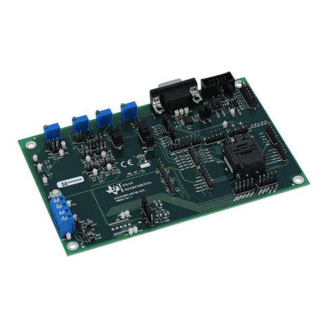
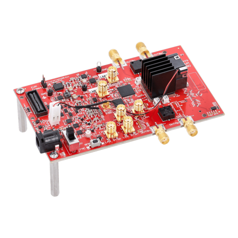
Figure 1-1. ADS131B26Q1EVM-PDK Evaluation Module...........................................................................................................1
Figure 1-1. ADS131B26Q1EVM-PDK PHI Connection and LED Indicators................................................................................5
Figure 2-1. ADC1A Current Input Circuit (Schematic)................................................................................................................. 7
Figure 2-2. ADC2A Sequencer Input Circuits (Schematic)..........................................................................................................7
Figure 2-3. ADC3A Voltage Input Circuit (Schematic)................................................................................................................. 8
Figure 3-1. External ADC Clock Options (Schematic)............................................................................................................... 10
Figure 4-1. DC/DC Converter and Transformer Driver Circuit (Schematic)............................................................................... 11
Figure 4-2. ADC Analog and Digital Supply Options (Schematic)............................................................................................. 12
Figure 5-1. ADS131B26Q1-PDK Jumper Default Settings........................................................................................................13
Figure 5-2. ADS131B26-Q1 Software Installation Prompt.........................................................................................................14
Figure 5-3. Device Driver Installation Wizard Prompts.............................................................................................................. 15
Figure 5-4. LabVIEW Run-Time Engine Installation.................................................................................................................. 15
Figure 6-1. EVM GUI Global Input Parameters......................................................................................................................... 16
Figure 6-2. Register Map Configuration.....................................................................................................................................17
Figure 6-3. Channel Configurations Register Page................................................................................................................... 18
Figure 6-4. Sequencer Configurations Register Page............................................................................................................... 19
Figure 6-5. Time Domain Display Tool ......................................................................................................................................20
Figure 6-6. Spectral Analysis Tool............................................................................................................................................. 21
Figure 6-7. Histogram Analysis Tool.......................................................................................................................................... 22
Figure 6-8. Sequencer Analysis Tool......................................................................................................................................... 23
Figure 7-1. Top Silkscreen......................................................................................................................................................... 28
Figure 7-2. Top Layer.................................................................................................................................................................28
Figure 7-3. Ground Layer.......................................................................................................................................................... 28
Figure 7-4. Power Layer............................................................................................................................................................ 28
Figure 7-5. Bottom Layer........................................................................................................................................................... 28
Figure 7-6. Bottom Silkscreen................................................................................................................................................... 28
Figure 7-7. Analog Inputs, ADC Power, and Interface Connections..........................................................................................29
Figure 7-8. Digital Isolators, DC/DC Power Supply, External Clock, and PHI Controller...........................................................30
List of Tables
Table 1-1. Related Documentation.............................................................................................................................................. 4
Table of Contents www.ti.com
2ADS131B26Q1EVM-PDK Evaluation Module SBAU413 – OCTOBER 2022
Submit Document Feedback
Copyright © 2022 Texas Instruments Incorporated
