Texi XYZ 2517 User manual

TEXI XYZ 2517

Directory
1. Instruction....................................................................................................................................................................1
1.1. Features.............................................................................................................................................................1
1.2. Composition..................................................................................................................................................... 1
1.3. Working Principles............................................................................................................................................1
1.4. Technical Parameters.......................................................................................................................................2
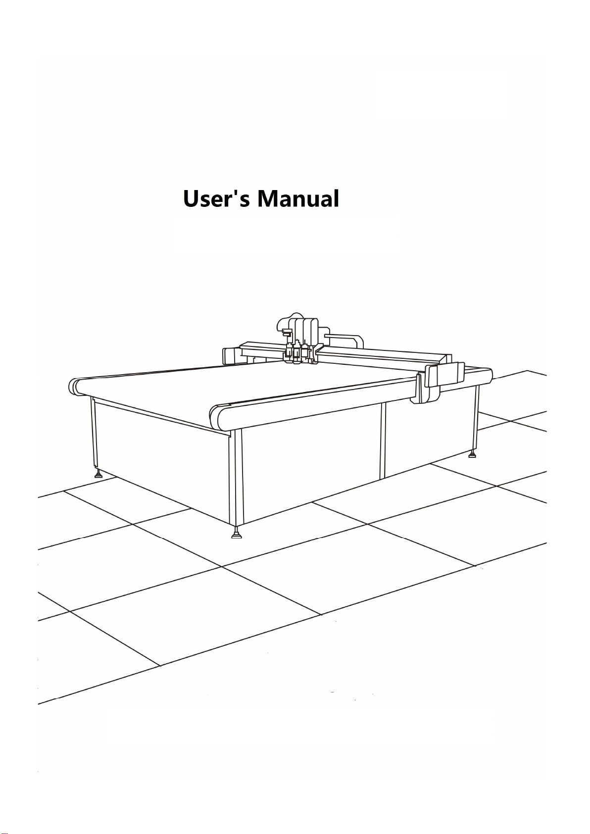
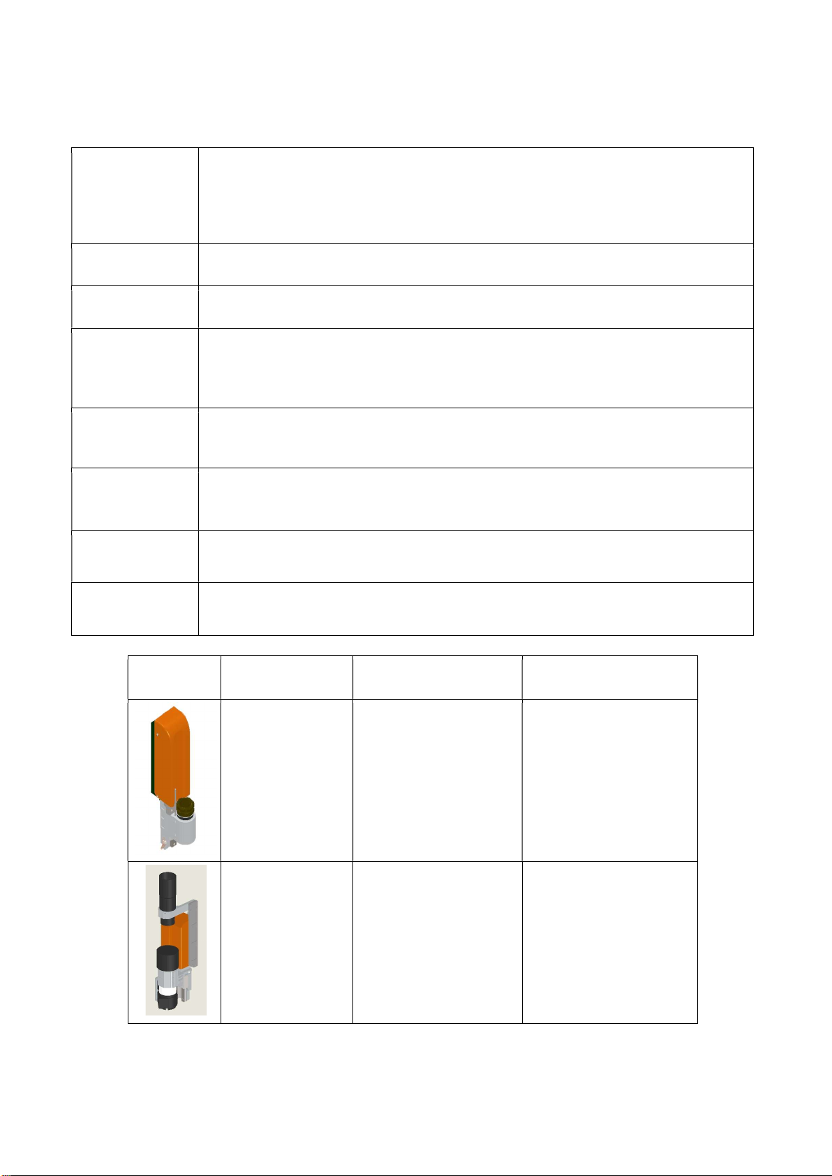
1.5. Cutting modules............................................................................................................................................... 3
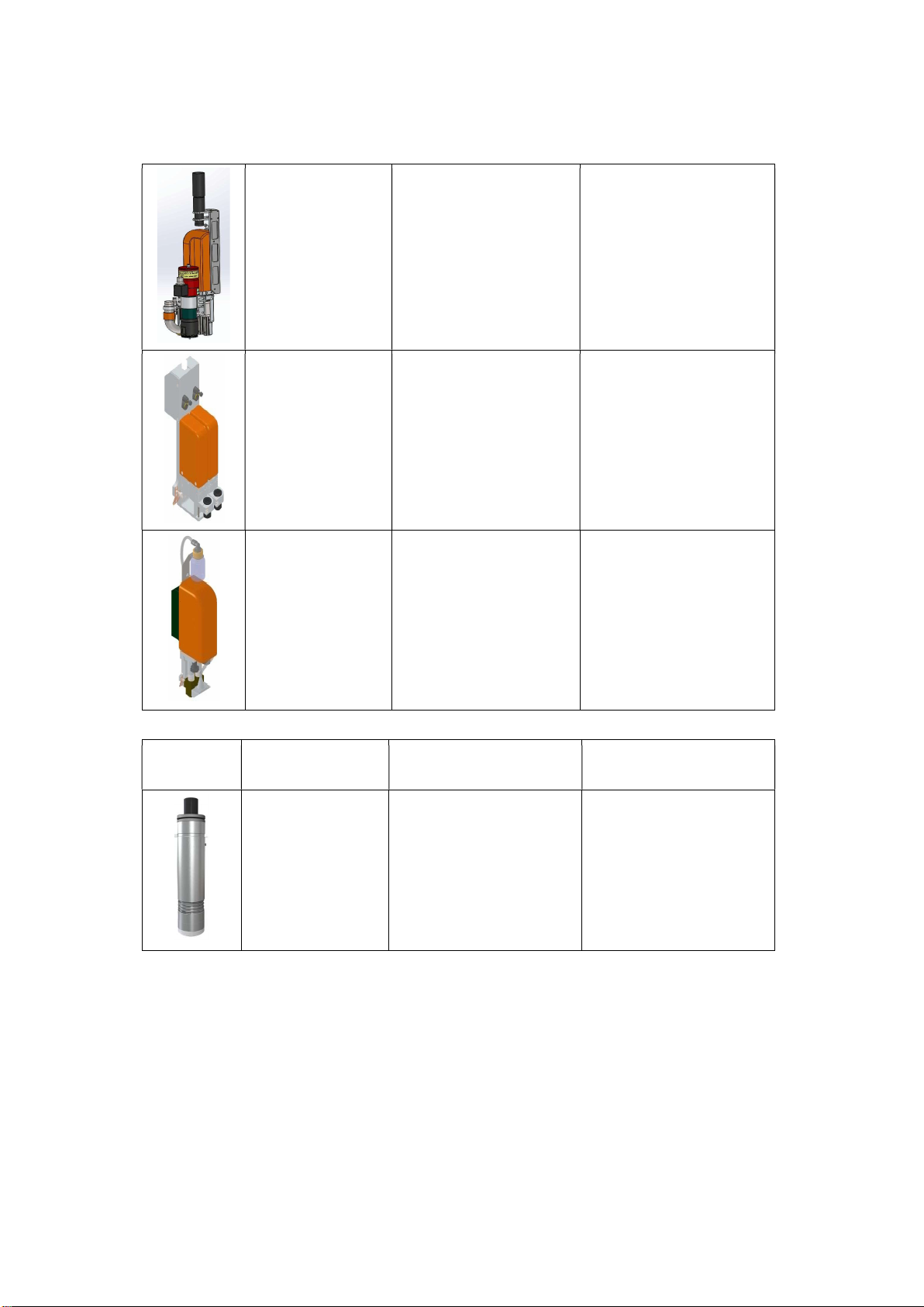
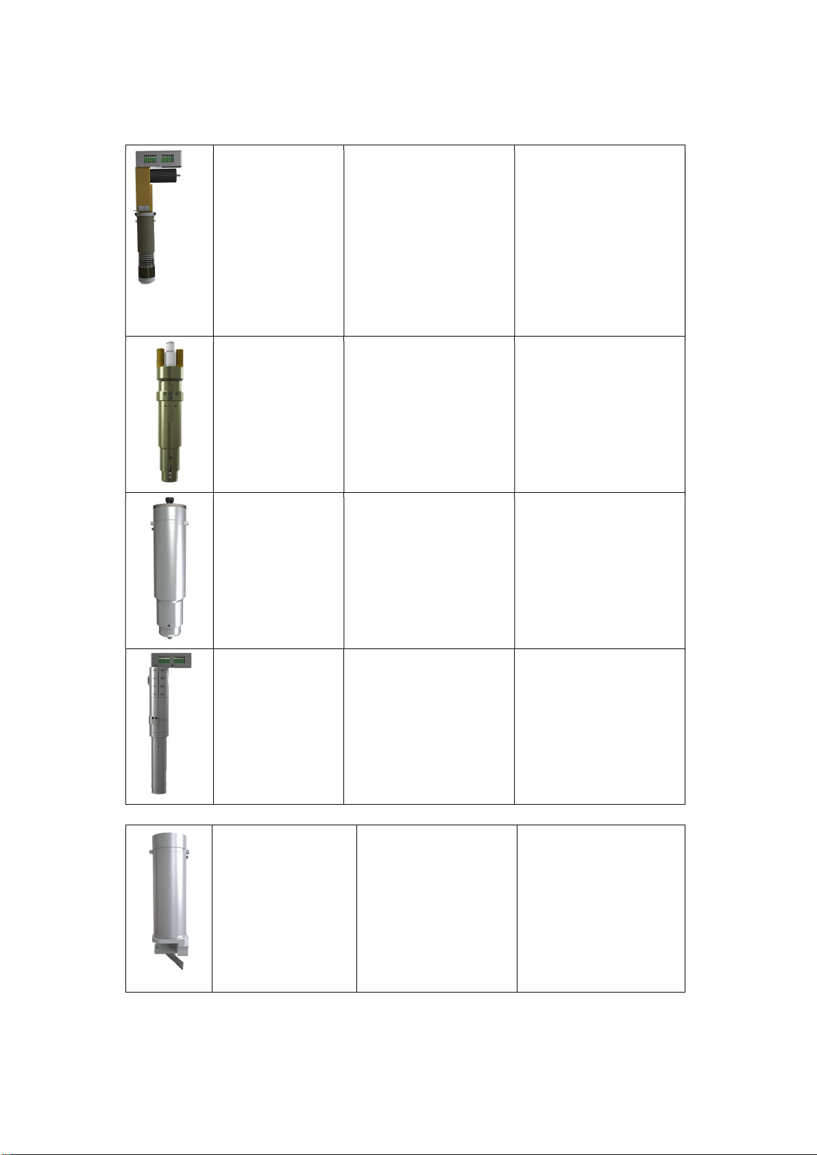
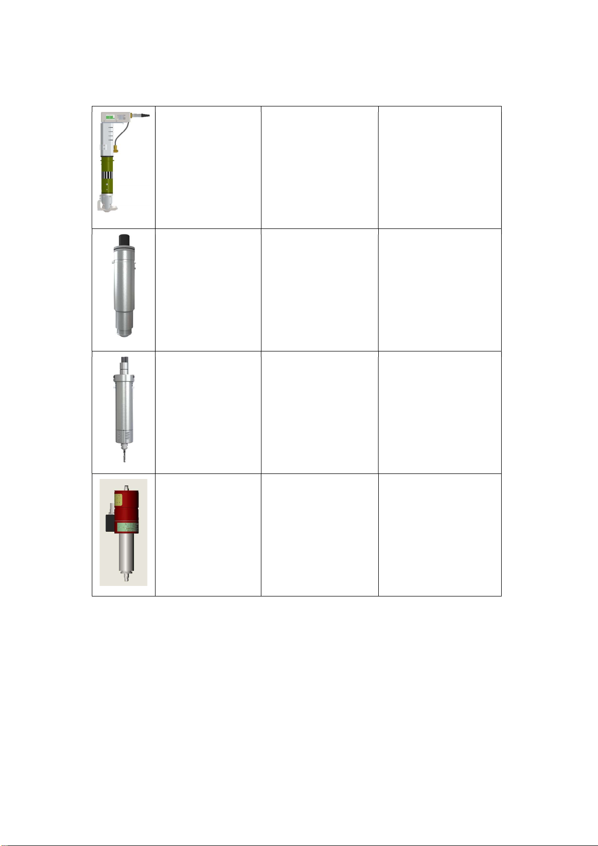
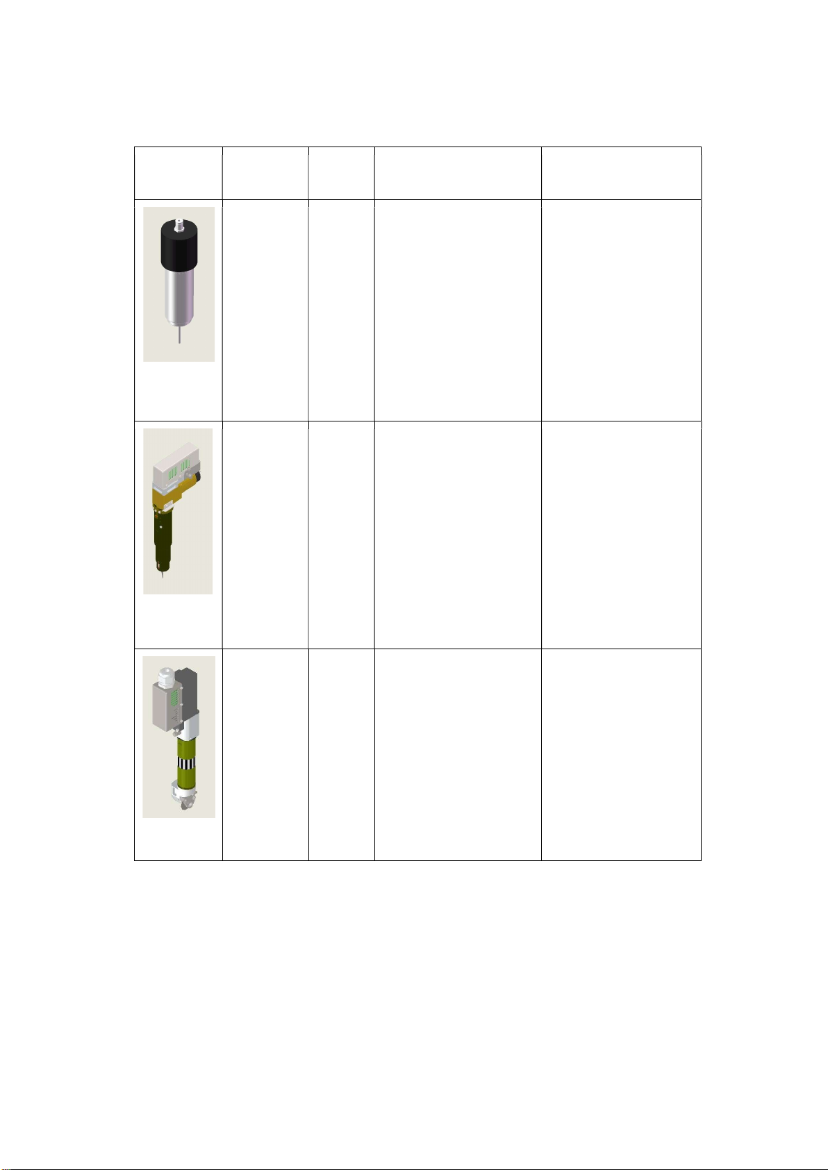
1.6. Tools..................................................................................................................................................................4
1.7. Circuit boards....................................................................................................................................................8
1.8. List of tools....................................................................................................................................................... 9
2. Preconditions..............................................................................................................................................................11
2.1. Installation location.........................................................................................................................................11
2.2. Personnel.........................................................................................................................................................11
2.3. Power requirement ( 50HZ / 60HZ Voltage±5% )................................................................................11
2.4. Environmental conditions.............................................................................................................................. 12
2.5. Basic device compressed air.......................................................................................................................... 12
2.6. Flooring Space Requirement...........................................................................................................................13
2.7. Operation Space requirement........................................................................................................................13
3. Installation................................................................................................................................................................. 14
3.1. Opening and inspecting packing crates......................................................................................................... 14
Note:..............................................................................................................................................................14
3.2. Initial leveling of the base frame.....................................................................................................................15
3.3. Base machine installation...............................................................................................................................16
3.4. Assembling the workstation............................................................................................................................20
3.4.1 Connect the monitor, keyboard and mouse.....................................................................................20
3.4.2 Connecting the PC to the cutter...................................................................................................... 21
3.5. Assemble the Milling support device. ( The total height : 2.8 m)................................................................22
3.5.1 Connect cables in the milling device support...................................................................................24
4. Danger area during initialization...............................................................................................................................25
4.1. Danger area on the module carriage..............................................................................................................25
4.2. Safety device on the machine and PC table....................................................................................................26
5. Power installation and air supply connection........................................................................................................... 27
6. Modules installation.................................................................................................................................................. 28
6.1. Tools installation.............................................................................................................................................30
6.1.1 Tangent tool......................................................................................................................................30

6.1.2 Electrical Oscillating Tool................................................................................................................32
6.1.3 V-Cut tool.........................................................................................................................................33
6.1.4 Big creasing tool.............................................................................................................................. 35
6.1.5 PRT tool............................................................................................................................................36
7. Operating....................................................................................................................................................................37
7.1. Preparation......................................................................................................................................................37
7.2. Operating.........................................................................................................................................................37
7.3. Maintenance...................................................................................................................................................38
7.3.1 Daily Maintenance........................................................................................................................... 38
7.3.2 Weekly Maintenance........................................................................................................................39
7.3.3 Monthly Maintenance...................................................................................................................... 41
7.3.4 Quarterly Maintenance......................................................................................................................41
7.3.5 Annual Maintenance.........................................................................................................................41
8. Troubleshooting.........................................................................................................................................................42
9. Safety attentions........................................................................................................................................................ 43


1
1. Instruction
1.1. Features
Regional vacuum zone
Vortex vacuum control
Automatic sheet feeding
Conveyor system
Camera registration system
High-speed and high-precision cutting tools
Collection table for cut out elements picking
No artificial help needed
1.2. Composition
TEXI XYZ 2517 series digital cutting machine is composed of Electrical box, Main body, Vacuum and Auxiliary devices.
Software includes file processing part and machine controlling part.
According to user’s demand, one or more tools can be used: Tangent Tool, Oscillating Tool, Kiss-Cut Tool, Router, V-
Cut Tool, Creasing Tool, Driven Rotary Tool, North & Drill Tool, Pen.
User can use bar code scanner to scan the bar codes that created by RIP software.
1.3. Working Principles
Import the files by SmartCut/iBrightCut, the user can process the files(editing and nesting) and send the processed
cutting files to CutterServer. According to the cutting files, the controlling system will create motion control signals. With
the signals, servo motors execute the tools lift/down and modules movement. Thereby, the machine achieves the high-
speed and high-precision cutting.
1.4. Technical Parameters
Model TEXI XYZ 2517
Cutting Area 2500mm*1700mm
Machine Dimension
3300mm*2520mm
Max Speed 1500mm/s
Accuracy 0.1mm
Max Cutting
Thickness 50mm
Modules 1-3

2
File formats
DXF、PLT、PDF、HPG、HPGL、TSK、BRG、XML、CUT、OXF、ISO、
AI、PS、EPS
Interface Serial Port / USB Port
Adsorption Vacuum Pump
Power Single-phase 220V / 2kw Three-phase
220V / 380V / 5.5kw/7.5kw
Power requirement
220V/50HZ/60HZ, 380V/50HZ/60HZ(Three-phase five-wire system)
Air pressure
requirement 0.6—0.85MPa,Dry compressed air
Operating
environment Temperature:0℃-40℃; Humidity:20%-80%RH
Storage
temperature - 20 to + 55°C
1.5. Cutting modules
Picture Name Feature Cutting Material
Universal Module All tools can be installed
in Cutting thickness:50mm
1.8KW
Module
Router
Power:1.8KW
60000rpm
Water cooling
cleaning device
Cutting thickness:
2mm Di-bond
20mm Acrylic

3
1kw
Module
Router
Power:1kw
60000rpm Air
cooling
cleaning
device
Cutting thickness:
2mm Di-bond
20mm Acrylic
Marking Module Two pens
3 times/s/pen Material thickness:50mm
North & Drill
Module
Two heads
3 times/s/head Material thickness:10mm
1.6. Tools
Picture Name Feature Materials
Tangent Tool
Universal Cutting Tool for
materials up to 5mm thick.
Fast speed and low cost.
Cardboard, Chevron
board, ABS board, Gasket,
Carbon fiber prepreg, PVC
tarpaulin, PE, XPE, Label,
etc.

4
Electrical
Oscillating Tool
High-frequency electric-
driven tool with
80W and 250W power
options. Max cutting speed
1m/s for soft and medium-
density materials.
Chevron board,
Corrugated board, Gasket,
KT board, Gray cardboard,
PE, XPE, EPE, PU leather,
PU composite sponge, Coil
car mat, etc.
Pneumatic
Oscillating Tool
Powerful air-driven tool
with extended stroke for
dense materials up to
50mm thick.
Composites, Honeycomb
board, Asbestos gasket,
Graphite gasket, Sponge,
EPE, etc.
Kiss-Cut Tool Half-cut tool for
vinyl materials.
Vinyl, sticker, reflective
film, etc.
Driven Rotary Tool
Cutting tool with driven
rotary blade for fabrics and
technical textiles with high
processing speed.
Fabrics, carbon fiber, glass
fiber, aramid, carpet, etc.
V-Cut Tool
Tool with 5 cutting
angles. Create 3D
structural design.
Honeycomb board,
sandwich board, KT
board, Gray board, etc.

5
Powerful Rotary Tool
Powerful tool with driven
rotary blade.
Technical textiles, carbon
fiber, glass fiber,
carpet, fur, etc.
Creasing Tool
Creasing wheels
carton box making.
for
Corrugated board, carton
board, etc.
Milling Router
Routing tool
high-performance
routing on
hard tough
materials
up 16mm
thick.
with
and
to
Acrylic, Di-bond,
aluminium composite,
MDF, etc.
Milling Router
Routing tool with
high-performance
routing on hard and tough
materials up to
16mm thick
Acrylic,Di-bond,
aluminium composite,
MDF, etc.

6
Picture Name Ab Feature Material
CNC
Router
MILL
1.8KW
Routing tool with
high-performance
routing on hard and
tough materials up to
20mm thick.
Power: 1.8KW;
RPM:60000rpm;
Max thickness:20mm.
Acrylic, Di-bond,
aluminum
composite, MDF,
etc.
Electrical
Oscillating
Tool EOT3
High-frequency electric-
driven tool with
200W power options.
Max cutting speed
1m/s for soft and
medium-density
materials.
Chevron board,
Corrugated board,
Gasket,KT board, Gray
cardboard,PE,XPE,
EPE,PU leather,PU
composite sponge, Coil
car mat, etc.
Super
Powerful
Rotary Tool
SPRT
Super Powerful tool with
driven rotary blade.
textiles, carbon fiber,
glass fiber, carpet, fur,
etc.

7
Perforating
tool PTK
Perforating tool
KT board 、
Corrugated
cardboard, paperboard,
cardboard, etc
Universal
drawing tool
UDT
Universal
drawing tool
Stencils, technical
labeling ,labeled
paper,etc,

8
1.7. Circuit boards
Board positions in electrical box
Board positions on machine
1.8. List of tools
Image
Description
Activity
Various Allen keys (SW 1.5 to 8)

9
Various open-ended spanners
(SW 5.5-19.2x10)
various Phillips and slotted
screwdrivers
screwdriver
Ratchet set with bolt nuts and Allen
inserts
Dial gauge (resolution of 0.1 mm)
To align the table plate

10
Image
Description
Activity
Holder for dial gauge support
Table plate: set height
Electric drill
Side cutters
to open the transport locking
devices
Measuring tape
Precision spirit level (recommended value
0.05 mm/m)
To level the machine

11
Precision spirit level
To level the machine foot
2. Preconditions
2.1. Installation location
Make sure that the following requirements are met:
• the installation location is level and can withstand the floor loads.
• the shipping crates can be deposited close to the installation location and their presence does not prevent
the machine from being assembled.
• the aisle width from the unloading location to the installation location is at a minimum the width
required for the dimensions of the packing crates.
• the electrical and air connections meet the requirements listed in the technical data.
• the installation location is well-lit.
• At least 1 meter of space is available all around the cutting system for service and daily operation.
2.2. Personnel
Make sure that the following requirements are met:
• the support personnel wear safety clothing and work gloves.
• the support personnel are familiar with the hazards associated during machine installation and
have read and understood the mounting instructions.
2.3. Power requirement ( 50HZ / 60HZ Voltage±5% )
Three
-phase
Vacuum
Pump
Voltage
Electric
Current
Air
Circuit
Breaker
Wire
Size
Wiring System
5.5KW
380V
8.3A
20A
6mm²
L1、L2、L3、N、G
7.5KW
380V
12A
20A
6mm²
L1、L2、L3、N、G
Three
-phase
Vacuum
Pump
Voltage
Electric
Current
Air
Circuit
Breaker
Wire
Size
Wiring System

12
5.5KW
220V
14.5A
30A
6mm²
L1、L2、L3、G
7.5KW
220V
20A
50A
8mm²
L1、L2、L3、G
Single-phase
Machine +PC
Electric
Current
Air
Breaker
circuit WireSize
Wiring
System
220V
10A
15A
6mm²
L、N、G
2.4. Environmental conditions
Value
Unit
Operating temperature
+ 10 to + 35
°C
Storage temperature
- 20 to + 55
°C
Relative humidity
10 - 80,
noncondensing
%
2.5. Basic device compressed air
Conveyor feeding clamps
Value
Units
Operating pressure
0.6
MPA
Min. air flow
0.4
m³/min
Control of Pot tool, supply of 1kw Router
Value
Units
Operating pressure
0.8
MPA
Min. air flow
0.6
m³/min
2.6. Flooring Space Requirement
Machine Dimension:Length X Width (With Router, the height of regular route holder is 2.8meter)
Material loader
Length / width
With
Length
Length+1.9m
Width
Width+0.9m
Without
Length
Length+0.9m
Width Width+0.9m
2.7. Operation Space requirement
Machine Dimension: Length X Width (with Router, the height of regular route holder is 2.8meter)
Feeding Frame
Length / width
With
Length
Length+3.4m
Width
Width+2.4m

13
Without
Length
Length+2.4m
Width Width+2.4m

14
3. Installation
3.1. Opening and inspecting packing crates
A Remove all screws on the upper side of the packing crate.
B Remove the cover and place it to one side.
C Remove the screws from the upper crossbars D Remove the crossbars and place them to one side
E Loosen the screws of the side cover.
F Remove the side cover.
G Make sure the contents are complete and without damage.
3.2. Initial leveling of the base frame
A Lift each side support end to keep the balance by precision spirit level.
B Determine the lowest position of the foot and use the setscrews to adjust it upwards.
C Use the setscrew to raise the position of the lowest foot.
Note:
Prevent
the
crate
cover
from
warping
when
placed
at
an
angle.
Place
the
packing
crate
level.
Note:
•
Only
complete
the
installation
if
all
parts
are
present
and
undamaged.
•
Inform
customer
service
if
any
parts
are
missing
or
damaged.
•
Replenish
or
replace
missing
or
damaged
parts.

15
M16
x
70
mm

16
3.3. Base machine installation
Picture 1
Table of contents
Popular Industrial Equipment manuals by other brands

Festo
Festo HGR A Series operating instructions

Allied Systems
Allied Systems SDN Installation maintenance and service manual

Dando
Dando TERRIER Mk 1 Operating and maintenance manual

bora
bora UUE1 Mounting and installation instructions

RUD
RUD VCGH-S Safety instruction

Siemens
Siemens SIWAREX R operating instructions

BLAUBERG Ventilatoren
BLAUBERG Ventilatoren HW installation instructions

Trotec
Trotec SpeedMarker 1600 operating manual

BAC
BAC VTL Rigging and Installation Manual

Siemens
Siemens SIVACON S4 manual

Eaton
Eaton Airflex WCB2 Series Installation, operation and maintenance

SteelMax
SteelMax Torch Runner Operator's manual