Texim Europe Sol Chip Comm Wireless Solar Tag System Kit Installation guide
157 Jaffa Street, "Amot Building" Haifa Israel ,35251 Fax + (972) 4 6228513 . Tel + (972) 4 8216942
157 Jaffa Street, "Amot Building" Haifa Israel ,35251 Fax + (972) 4 6228513 . Tel + (972) 4 8216942
Installation and Operating Guide:
Sol Chip Comm™ Wireless Solar Tag System Kit
Document version: 0.5
Document History
Date
Version
Version Description
February 26, 2017
0.1
Initial version
March 1, 2017
0.2
March 8, 2017
0.21
Add box picture, removed comments
May 5, 2017
0.3
Updated with new IoT Portal
May 14, 2017
0.4
Added User Profile Settings
May 28th, 2017
0.5
Portal Screenshot update
What You Can Do with this System Kit
Thank you for purchasing Sol Chip’s remote sensor monitoring
system kit, a full IOT (“Internet Of Things”) system that you
can quickly install by yourself in a simple way. After the quick
installation of this pre-integrated kit, everything works
automatically and you have a full-fledged wireless sensor
monitoring system that periodically monitors the following
parameters: soil moisture, air temperature, and air humidity,
and sends these parameters to the internet Cloud. This real-time
actionable sensors’data is an enabler of IOT applications such
as Precision Agriculture, Smart Irrigation and Smart City
applications. The system is capable of working for years with
no need for any service or maintenance.
The installation is as simple as performing four straight forward steps:
1. Connect the sensors to the Wireless Solar Tags
2. Place the sensors in the desired locations
3. Install the wireless gateway and plug it to the AC power
4. Activate your account at the Sol Chip website
Once powered, the wireless gateway will connect to the cellular network and start pulling soil moisture
air temperature and air humidity data from the sensors every 30 minutes and upload the retrieved data
to Sol Chip’s website.
Once your Sol Chip website account is activated, you can access your sensors’ data, and get customized
graphs.
In the following paragraphs a step by step installation guide is provided.
157 Jaffa Street, "Amot Building" Haifa Israel ,35251 Fax + (972) 4 6228513 . Tel + (972) 4 8216942
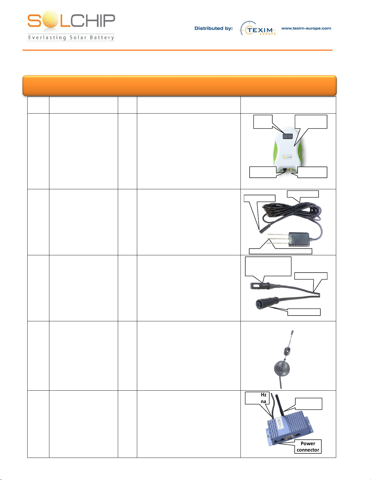
Kit Content Detailed Description
Item
no.
Item name
Qty.
Description
Picture
1
Sol Chip Comm™
Wireless Solar Tag –
SCC
2
The SCC is an all-weather, solar
powered device that connects to
the sensor, provides the sensor
with power and wirelessly
connects it to the wireless
gateway. The sunlight energy is
harvested during day light time
and stored in an internal energy
storage.
Solar
panels
Sensor
connector
Antenna
connector
All weather
resistant box
2
Soil Moisture Sensor
1
The soil moisture is measured by
injecting the 3 spokes into the
ground. The sensor is controlled
via the cable (which connects to
one of the SCCs)
Plugged into the ground
Sensor cable
Connector
3
Air Temperature and
Humidity Sensor
1
The dual purpose sensor is
controlled through the cable
(which connects to the 2nd SCC)
Dual Purpose (Air
Temperature and
Humidity) Sensor Sensor cable
Connector
4
433MHz Antenna
3
Magnet Base Antenna. Used for
the 433MHz radio
communication between the
SCC’s and the Wireless
Gateways
5
Sol Chip Comm™
Wireless Gateway
1
The Wireless Gateway collects
the data from the sensors via the
SCC and uploads to Sol Chip
website via cellular
communication. The device is
AC powered and can be placed
up to 1,500m (approx. 1 mile)
from the SCC (in line of sight
Power
connector
433MHz
antenna Cellular
antenna
Attention: Carefully unpack the Demo kit. When unpacking, care should be taken to prevent dropping

157 Jaffa Street, "Amot Building" Haifa Israel ,35251 Fax + (972) 4 6228513 . Tel + (972) 4 8216942
Item
no.
Item name
Qty.
Description
Picture
conditions. Distance will be
shorter in non-line of sight
conditions)
6
Cellular Antenna
1
Plugged into the gateway in
order to access the cellular
network
7
Wireless Gateway
Power Supply +
Wall Adaptor
1
Powers the wireless gateway
4 pin “Molex”
Connector AC
Adaptor
8
SCC Charger + Wall
Adaptor
1
This accessory is provided to
quickly charge the SCC if
internal energy storage is
depleted
Plugged into
the SCC sensor
connector
AC
Adaptor
9
Magnet
1
This accessory can be used to
manually activate sampling of
data from the sensor and
transmission to the gateway, as
opposed to waiting up to 30
minutes for the next automatic
transmission. This is done by A
magnet touch the SCC (not used
on a regular basis)
10
User account
Activation to the
sensor visualization
service
1
The system is already pre-
integrated with Sol-Chip Portal.
Locate the account activation
email to start the registration
process.
11
Installation guide
1
This document
12
Sol Chip SCC-S433
Wireless Solar Tag
product brief
1
13
Sol Chip Wireless
Gateway user
manual
1

157 Jaffa Street, "Amot Building" Haifa Israel ,35251 Fax + (972) 4 6228513 . Tel + (972) 4 8216942
Item
no.
Item name
Qty.
Description
Picture
14
Soil Moisture sensor
data sheet
1
15
Air Temperature and
humidity sensor data
sheet
1
157 Jaffa Street, "Amot Building" Haifa Israel ,35251 Fax + (972) 4 6228513 . Tel + (972) 4 8216942
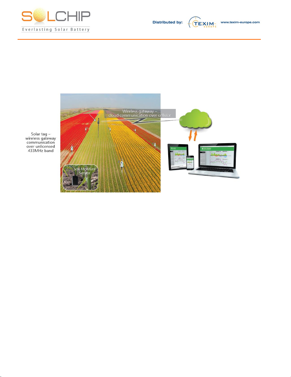
Kit Deployment Guidelines and Tips
Below is a general schematic showing multiple SCCs installed in a field, connected to a single Wireless
Gateway which in turn sends the sensors’ data to the Sol Chip website. The website is accessible to the
user in real time via his/her mobile device, tablet or PC.
Please read this entire guide before installation of the system, then install according to the following the
steps in this document.
While planning the deployment of the equipment, it is recommended to observe the following
guidelines:
1. The sensors and the SCC are co-located, as they are connected to each other via the sensor cable
2. The sensors and SCCs are all-weather (IP-67 compliant) hence can be placed outdoor, (e.g. in
an agricultural field) and operate in temperatures from -20C to +80C, exposed to rain, etc.
3. The SCC solar panels need few hours of sunlight each day. These few hours allow the tiny solar
panels to harvest enough energy for continuous operation day and night, summer and winter,
year after year. The more non-obscured sunlight the better of course. Light intensity within
greenhouses is typically sufficient
4. The higher the SCC 433MHz antenna will be placed the further the gateway can be located, up
to 1,500m (approx. 1 mile) distance between the SCC and the wireless gateway in a non-
obscured line of sight conditions.
5. Make sure you have proper cellular coverage at the intended location for the wireless gateway
The wireless gateway and its power adaptor need to be plugged into an AC outlet (100v-240v) and
should be placed in a location that is protected from rain.
157 Jaffa Street, "Amot Building" Haifa Israel ,35251 Fax + (972) 4 6228513 . Tel + (972) 4 8216942
Detailed Installation Guideline
Prior to installation in the field, it is highly recommended to connect and activate the system in your
office or lab. This will help you to get familiar with the system and make sure that everything is
operational prior to placing it in the field.
In order to activate in your office / lab, perform the procedure below, skipping steps: 2a, 2b, 2c, 2e, and
3b. For your convenience, we marked these steps with “*”.
After verifying in the lab / office that the system is operational, you can go ahead and install the system
in the desired site –where you should perform all the steps without skipping any.
1. Connect the sensors to the Wireless Solar Tags:
a. Connect the soil moisture sensor cable to the SCC #1’s sensor connector (black)
Similarly, connect the air temperature and humidity sensor cable to the second SCC #2
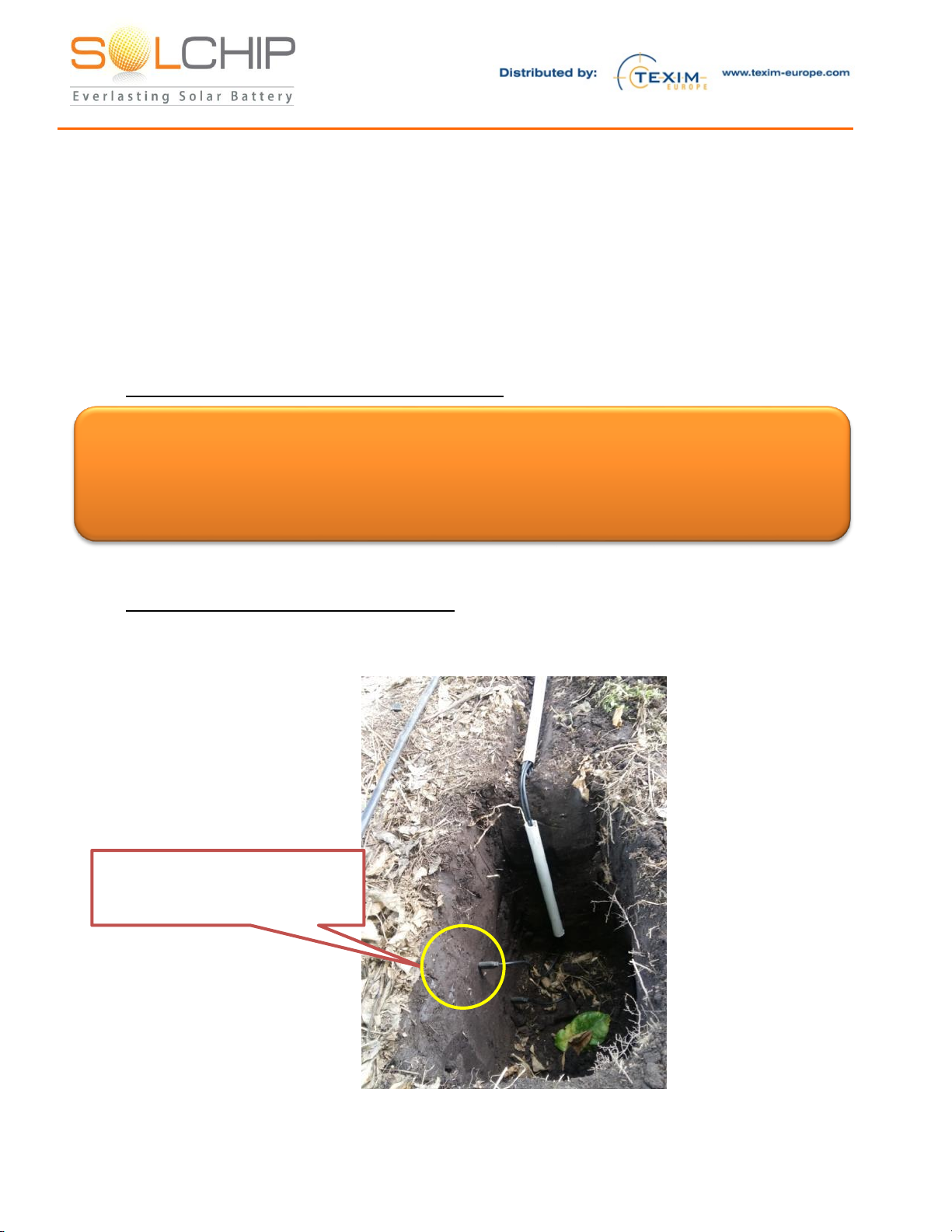
2. Place the sensors in the desired locations:
a. * Stick the spokes of the soil humidity sensor into the soil its moisture you intend to
monitor. In case you desire to measure the soil moisture close to the plant’s roots it is
possible to bury the entire sensor, as seen below:
b. * Place the air temperature and humidity sensor at the desired location (can be distant
from the other SCC)
Soil Moisture Sensor placed
underground (to be covered with
soil)
Attention: One should be very careful while handling the SCC Wireless Solar Tag output ports
(black connector). The sensor connector pins are connected to the output of the internal
energy storage and have a potential of ~3.3V. Shortening the ports may discharge the
internal rechargeable battery very quickly, while damaging the internal circuitry

157 Jaffa Street, "Amot Building" Haifa Israel ,35251 Fax + (972) 4 6228513 . Tel + (972) 4 8216942
c. * Place each of the SCCs in a place exposed to sun light, up to the maximum height
from the sensor as per sensors’ cables length. Best energy results are obtained when unit
is pointed to area where maximal exposure to sunlight travel is obtained, (e.g. to the
south at northern hemisphere countries). The devices should be placed vertically so that
rain, snow or dirt will not build up on the solar panels. Use zip ties or iron wire to attach
the SCCs to the desired place (e.g. plant, pole, etc.)
d. Connect the cable of a 433MHz (magnetic base) antenna to each of SCCs’(golden)
connectors
e. * For best radio communication performance, it is recommended to place the 433MHz
antennas highest as possible –to get minimal obstruction, by leaves, walls, etc. The
antenna has a magnet base that will make installation on a metal surface very easy.
While attaching the antenna base to a metallic surface is perfectly OK, please note that
metal elements that are located between the SCC antenna and the gateway might
seriously affect the radio communication or even totally block it. For best
communication it is desired to have a direct line-of-sight path free of metal obstacle
between antenna and gateway. Both the gateway’s and SCC’s antennas should be
installed in same, vertical orientation.
f. The SCC’s energy storage are pre-charged hence start working automatically, and
transmit their respective sensor’s data every 30 minutes
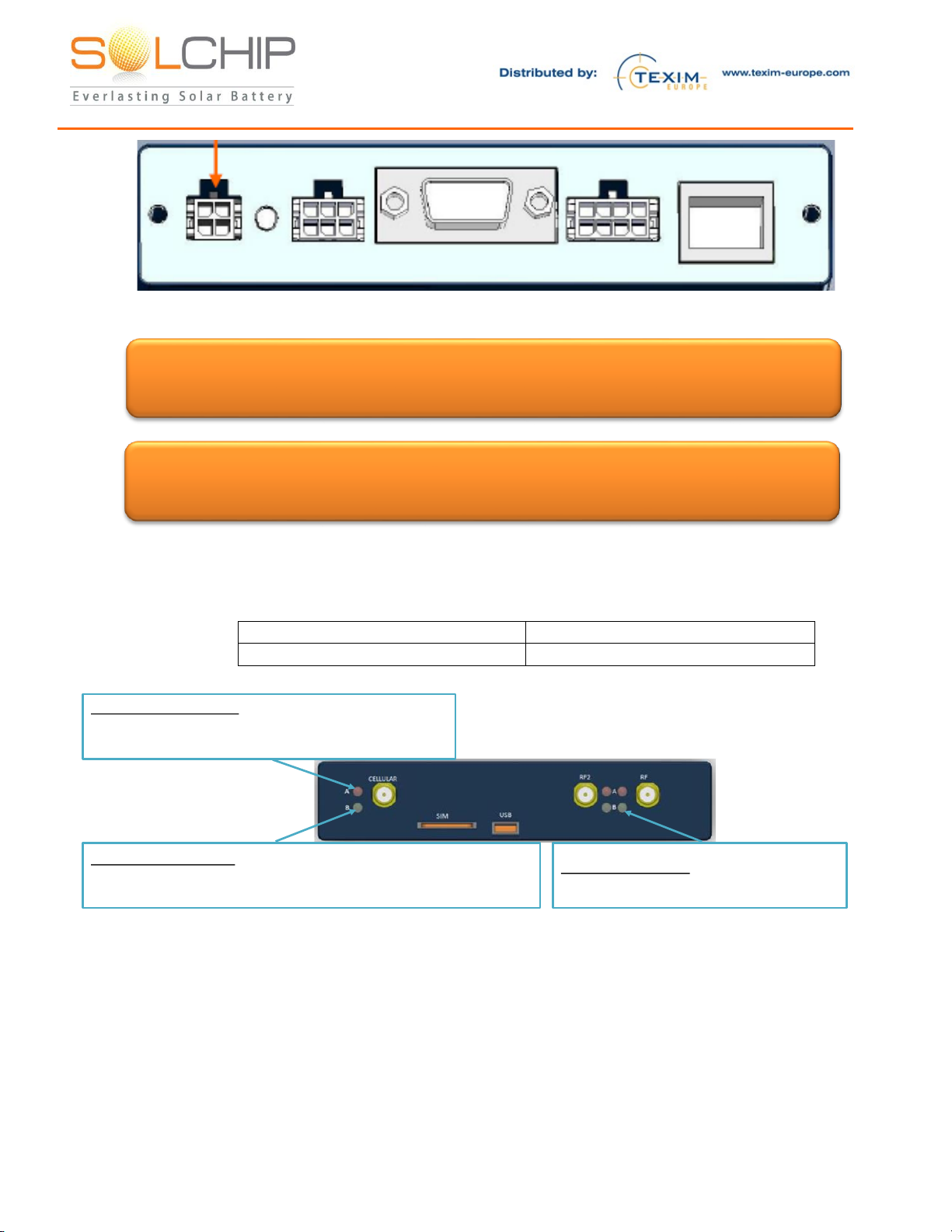
3. Install the wireless gateway and plug it to the AC power:
Below is a drawing of the wireless gateway front panel. Note that in some models the “RF2”
connector is not populated.
a. Connect the cable of the 433MHz (magnet base) antenna to “RF”connector
b. * For best radio communication performance, it is recommended to place the 433MHz
antennas highest as possible –to get minimal obstruction, by leaves, walls, etc. The
antenna has a magnet base that will make installation on a metal surface very easy.
While attaching the antenna base to a metallic surface is perfectly OK, please note that
metal elements that are located between the SCC antenna and the gateway might
seriously affect the radio communication or even totally block it. For best
communication it is desired to have a direct line-of-sight path free of metal obstacle
between antenna and gateway. Both the gateway’s and SCC’s antennas should be
installed in same, vertical orientation.
c. Connect the cellular antenna to “Cellular”connector
d. Connect the AC power adaptor to the 4-pin “Molex” connector on the left of the
Wireless Gateway Panel, as shown below:
157 Jaffa Street, "Amot Building" Haifa Israel ,35251 Fax + (972) 4 6228513 . Tel + (972) 4 8216942
e. Plug the gateway to AC power
f. The gateway has an internal SIM card. Upon power-up the gateway will automatically
connect to the 2 SCC units and to the cellular network. Upon successful connection,
expect to see within 1 minute the following LED indications:
Cellular A (Red LED)
ON
Cellular B (Green LED)
Slow Blink (every ~2 seconds)
“RF B” Green LED:
Blinks upon reception of data from SCC
“Cellular A” Red LED:
ON: The Gateway is connected to the server
OFF: The Gateway is not connected to the server
“Cellular B” Green LED:
Blinks quickly (~2 times per second) or ON: search for cellular network
Blinks slowly (every 2 seconds): connected to a cellular network
Attention: While the Wireless Gateway is operational, one should note that in order to
avoid permanent damage, neither cellular devices, nor SCC tags should be brought
near the gateway’s immediate surroundings (less than 20 centimeters)
Attention: The Wireless Gateway has limited lighting protection and it is the user’s
responsibility to install surge protection on the antenna and lighting protection near the
gateway unit
157 Jaffa Street, "Amot Building" Haifa Israel ,35251 Fax + (972) 4 6228513 . Tel + (972) 4 8216942
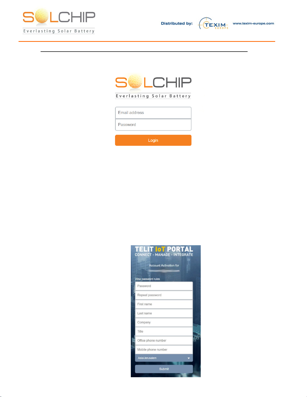
4. Activate your account at the Sol Chip IoT Portal (powered by Telit deviceWISE)
https://solchip.devicewise.net
a. You should have received an email with an invitation to activate your account.
Look for the following email:
From: Telit IoT Portal <noreply@devicewise.com>
Subject line: Welcome to the Sol-Chip Portal (powered by deviceWISE)
* If you cannot locate the email, contact your distributor or support@sol-chip.com
b. In the email, click on the activation link and proceed to create your account.
•Make sure to enter all of your information, select your time-zone and click Submit
157 Jaffa Street, "Amot Building" Haifa Israel ,35251 Fax + (972) 4 6228513 . Tel + (972) 4 8216942
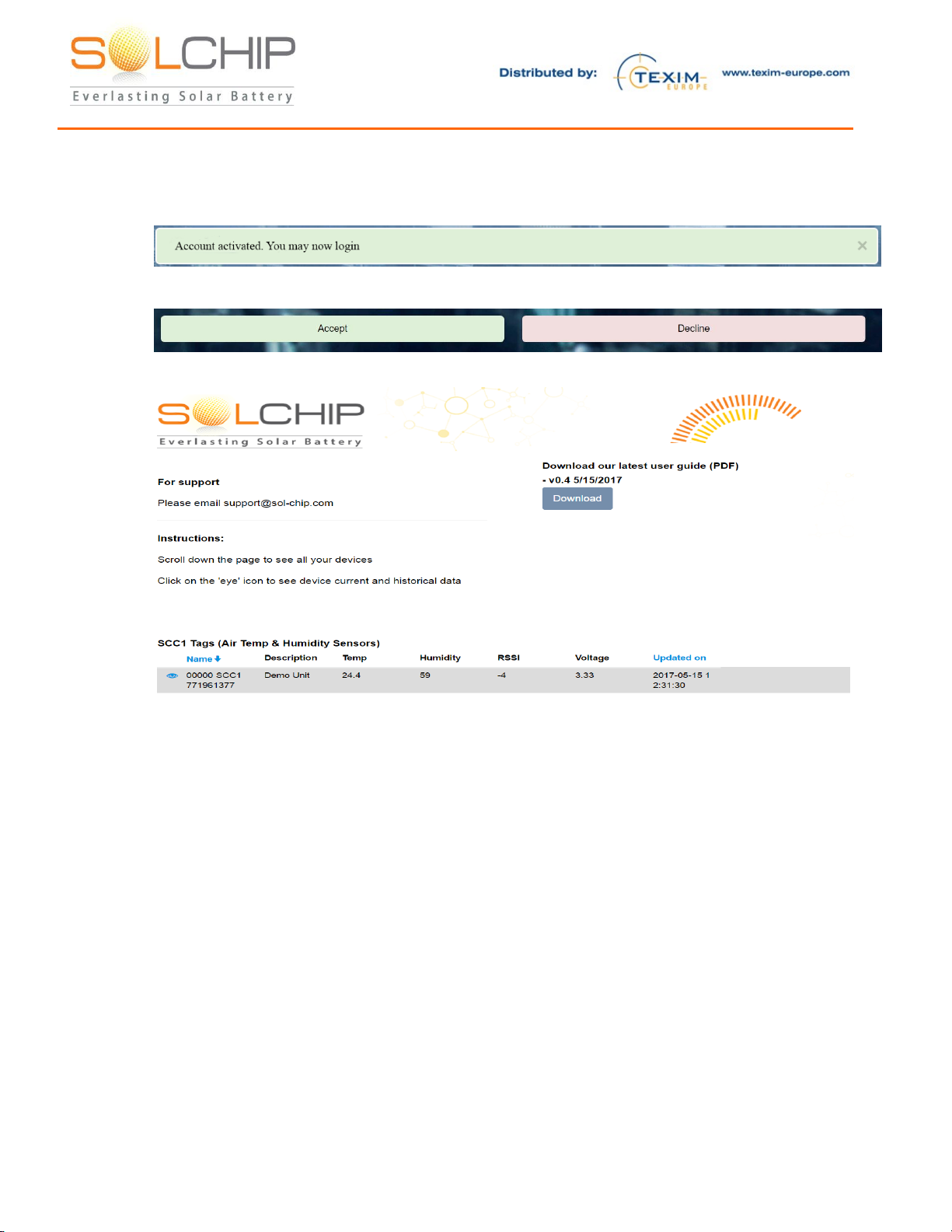
c. Your account is now activated, proceed to login
d. After login, please review and agree to the general terms and conditions, and privacy policy
of the portal.
e. After approving both pages, you will be taken to the Dashboard

157 Jaffa Street, "Amot Building" Haifa Israel ,35251 Fax + (972) 4 6228513 . Tel + (972) 4 8216942
5. Using the Sol Chip IoT Portal (powered by Telit deviceWISE)
Please note, we are constantly updating and improving the Portal, please watch
for release updates by email or in the Main Dashboard.
a. To login, go to https://solchip.devicewise.net and enter your login information
•If you forgot your password, use the “Recover account / Reset password” link to reset
your password. If you are still having trouble, contact your distributor or support@sol-
chip.com
b. Use the tool bar at the bottom of the screen to change your preferences
•To change time zone to view the data in the dashboard
•To select the time range of the graphs you can also use this tool:
•To update password
•To log out from your account
157 Jaffa Street, "Amot Building" Haifa Israel ,35251 Fax + (972) 4 6228513 . Tel + (972) 4 8216942
Operation
On-going operation:
The operation of the system is essentially seamless. Once everything is connected, each SCC
automatically reads its sensor every 30 minutes and immediately upload their data to the Sol Chip IoT
Portal. This data is stored and is accessible for viewing by the user.
We are constantly updating our services, always check the latest version of the user guide on our
website at https://solchip.devicewise.net
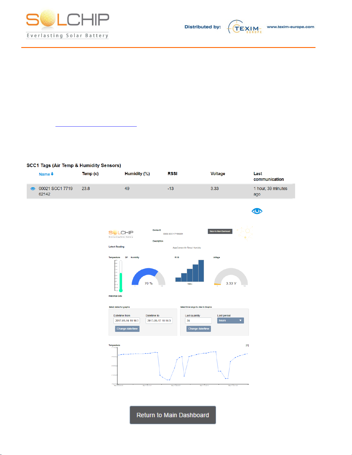
Navigating sensor data
After login, you will see the main dashboard with the latest information at a glance.
1. To see in depth information for each of the SCCs, click on the view icon ( ) at the left side
2. A new dashboard will open up with current sensors’ reading and historical data
3. To return to the Main Dashboard, click on the Return to Dashboard button
157 Jaffa Street, "Amot Building" Haifa Israel ,35251 Fax + (972) 4 6228513 . Tel + (972) 4 8216942
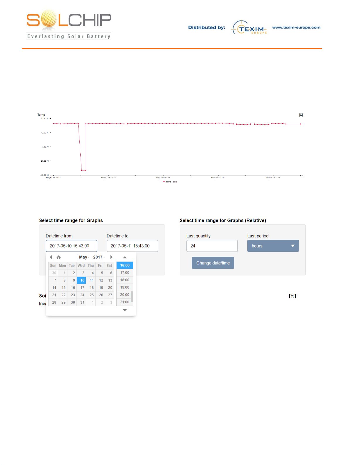
Sensor visualization service:
Below is an example of a Temperature sensor graph.
The user can set the time window to view historical data and horizontal zoom (shorter time higher
time resolution), by clicking on the date picker

157 Jaffa Street, "Amot Building" Haifa Israel ,35251 Fax + (972) 4 6228513 . Tel + (972) 4 8216942
Troubleshooting
Please note that each SCC System Kit was fully tested as a system prior to shipment. If you have
issues, please identify the indication you observe in the table below and follow the relevant
troubleshooting procedure:
Proce
dure
Indication
Potential
cause(s):
Steps
A
“Cellular A”
red LED at
the gateway
is OFF
Gateway is not
connected to the
server
1. Verify that the gateway is connected to the cellular
network (see no. 2 below)
2. Assuming that the gateway is connected to the cellular
network, restart the gateway by disconnecting the
power source and connecting again, and wait for 1
minute
3. From your PC / mobile, browse to
https://solchip.devicewise.net and verify that the
gateway is connected in the Main dashboard page.
4. If none of the above solves the problem, contact Sol
B
“Cellular B”
green LED at
the gateway
blinks
quickly (~2
times per
second), or
constantly lit
ON
The gateways is
searching for
network
1. Verify with your mobile device that there is proper
cellular coverage. If there are no networks available,
change the gateway location to a place with proper
coverage
2. Note that if you observe a cellular signal in your
mobile device, it may be that the SIM in the gateway
is configured to roam to a different network
3. If none of the above solves the problem, contact Sol
Chip support
C
No sensor
data is
collected,
while the
gateway is
connected to
the server
Issue with the
gateway;
No
communication
between SCC
and gateway;
The sensors are
not properly
connected to the
SCC tag;
SCC internal
energy storage is
depleted;
SCC is
malfunctioning
Perform the checks in the following order. After each
step, check if the problem still exists:
1. Verify that the gateways is operational, by following
the procedures A and B above
2. Perform manual activation of the SCC tag by touching
it with a magnet (see below). Watch the “RF B” green
LED –it blinks once upon reception of data from the
SCC.
3. If the LED blinks upon passing the magnet, the SCC,
the gateway, and the RF communication between
them are OK –now check that the sensor connector is
properly screwed and that the sensors appear visually
undamaged.
If the “RF B” green LED does not blink upon passing the
magnet, continue as follows:
4. Check 433MHz antennas on both the SCC and
gateway. Make sure that the connectors are properly
screwed and not damaged, and that the antennas are
both vertical, try to activate the SCC by passing the
magnet
157 Jaffa Street, "Amot Building" Haifa Israel ,35251 Fax + (972) 4 6228513 . Tel + (972) 4 8216942
5. Check if there are metallic or other obstructions
between the SCC and the gateway; try to activate the
SCC by passing the magnet
6. Bring the SCC closer to the gateway; try to activate
the SCC by passing the magnet
7. The SCC internal energy storage might be depleted –
check latest record of the SCC energy storage voltage
level (in Sol Chip’s portal). If depleted, disconnect the
sensor and connect the SCC charger instead; charge
the SCC for 6 hours. Disconnect the SCC charger and
connect the sensor again. try to activate the SCC by
passing the magnet
8. If none of the above solves the problem, contact Sol
Chip support
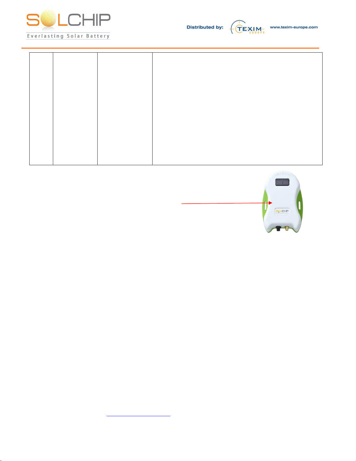
Manually forcing a transmission of the SCC:
If you want to get immediate reaction from the sensor, use the magnet to activate
the SCC as follows:
1. Bring the magnet close to the SCC at this point
2. “RF B” (Green) LED at the Wireless Gateway’s panel will blink once
3. You will see transmission at the web site within few seconds
Attention!
Please familiarize yourself with the important safety related notes below:
1. Carefully unpack the Demo kit. When unpacking, care should be taken to prevent dropping
2. One should be very careful while handling the SCC output ports. The sensor connector pins are
connected to the output of the internal energy storage and have a potential of ~3.3V. Shortening the
ports may discharge the internal rechargeable battery very quickly, while damaging the internal
circuitry
3. While the Wireless Gateway is operational, one should note that in order to avoid permanent
damage, neither cellular devices, nor SCC tags should be brought near the gateway’s immediate
surroundings (less than 20 centimeters)
4. The Wireless Gateway has limited lighting protection and it is the user’s responsibility to install
surge protection on the antenna and lighting protection near the gateway unit
5. The SCC-S433 contains a rechargeable battery. Whenever this unit is transported, the carrier’s
shipping constrains should be followed
6. Do not open any of the kit components. Any damage created due to opening the components is not
under Sol Chip’s responsibility
Support

Contact details
The Netherlands
Germany North
Nordic region
Belgium
Germany South
UK & Ireland
Austria
Elektrostraat 17
NL-7483 PG Haaksbergen
T: +31 (0)53 573 33 33
F: +31 (0)53 573 33 30
Bahnhofstrasse 92
D-25451 Quickborn
T: +49 (0)4106 627 07-0
F: +49 (0)4106 627 07-20
Sdr. Jagtvej 12
DK-2970 Hørsholm
T: +45 88 20 26 30
F: +45 88 20 26 39
Zuiderlaan 14 bus 10
B-1731 Zellik
T: +32 (0)2 462 01 00
F: +32 (0)2 462 01 25
Martin-Kollar-Strasse 9
D-81829 München
T: +49 (0)89 436 086-0
F: +49 (0)89 436 086-19
St. Mary’s House, Church Lane
Carlton Le Moorland
Lincoln LN5 9HS
T: +44 (0)1522 789 555
F: +44 (0)845 299 22 26
Warwitzstrasse 9
A-5020 Salzburg
T: +43 (0)662 216 026
F: +43 (0)662 216 026-66
General information
www.texim-europe.com
Table of contents


