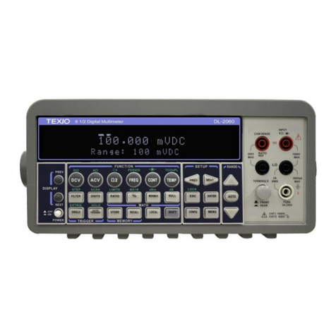
TEXIO DL-1060 User manual

INSTRUCTION MANUAL
6 1/2 DIGITAL MULTIMETER
DL-1060
DL-1060G/ DL-1060VG
DL-1060R/ DL-1060VR
B71-0180-31

CONTENTS
USING THE PRODUCT SAFELY··········································································· Ⅰ-Ⅲ
1 OVERVIEW ························································································································1
1.1 GENERAL INFOMATION ····································································································1
1.1.1 Feature Overview ···································································································1
1.1.2Inspection ·············································································································2
1.1.3Taking off the black rubber ring··················································································2
1.1.4The DL-1060’s Dimension ························································································3
1.1.5Update of the user's manual······················································································3
1.2 SETTING UP DL-1060 ·····································································································4
1.2.1 To adjust the handle································································································4
1.2.2 To connect the power ······························································································6
1.2.2.1 To convert the voltage ········································································································6
1.2.2.2 To change the power-line fuse································································································9
1.2.2.3 To change the current input fuse··························································································· 13
1.2.3 Factory Default When Power-ON ············································································· 16
1.3 DL-1060 FUNCTION INTRODUCTION ·················································································· 17
1.3.1 The Front Panel ··································································································· 17
1.3.2 The Display········································································································· 19
1.3.2.1 Annunciators··················································································································· 19
1.3.3 The Rear Panel···································································································· 20
2 BASIC MEASUREMENT FUNCTION····················································································· 21
2.1 VOLTAGE MEASUREMENTS (DCV &ACV)··········································································· 21
2.2 RATIO MEASUREMENTS (DC VOLTAGE ONLY)······································································· 22
2.3 CURRENT MEASUREMENTS (DC &AC) ·············································································· 24
2.4 RESISTANCE MEASUREMENTS (2 &4-WIRE)········································································· 25
2.5 FREQUENCY &PERIOD MEASUREMENTS············································································· 26
2.6 CONTINUITY MEASUREMENTS·························································································· 28
2.7 DIODE MEASUREMENTS································································································· 29
2.8 TEMPERATURE MEASUREMENTS ······················································································ 30
2.8.1 Thermocouple Measurements ················································································· 31
2.8.2 RTD Measurements ······························································································ 31
2.8.2.1 2-Wire RTD Measurements································································································ 32
2.8.2.2 3-Wire RTD Measurements································································································ 32
2.8.2.3 4-Wire RTD Measurements································································································ 33
2.9 CAPACITANCE MEASUREMENTS ······················································································· 34
2.10 2ND MEASUREMENT··································································································· 35
3 FRONT PANEL OPERATIONS····························································································· 38
3.1 MEASUREMENT CONFIGURATION······················································································ 38
3.1.1 Set ADC (Auto Zero) ····························································································· 38
3.1.2 Filter ·················································································································· 40
3.1.2.1 AC Filter (AC only)··········································································································· 40
3.1.2.2 Digital Filter ······················································································································ 41
3.1.3 Resolution & NPLC Setting····················································································· 44
3.1.4Threshold Resistance (Continuity)············································································ 46
3.1.5Range (Manual & Auto)·························································································· 47
3.1.6Rate (Integration Time) ·························································································· 48
3.1.7Sensor Selection for Temperature Measurements························································ 50
3.1.8Remote Interface Selection····················································································· 55
3.2 TRIGGER OPERATIONS·································································································· 58
3.2.1 Trigger Mode ······································································································· 59
3.2.2 Trigger Source ····································································································· 61
3.2.3 Trigger Setting ····································································································· 62
3.3 MATH OPERATIONS······································································································ 66
3.3.1Percent(%)·········································································································· 67
3.3.2Average (AVG/MIN/MAX/COUNT)············································································ 68
3.3.3Null(Relative)······································································································· 69
3.3.4Limits Test ·········································································································· 70
3.3.5MX+B················································································································· 72
3.3.6dB/dBm ·············································································································· 73

3.4 SYSTEM RELATED OPERATIONS······················································································· 76
3.4.1 Display··············································································································· 76
3.4.2 Beeper ··············································································································· 77
3.4.3 Reading Memory (Store & Recall) ············································································ 79
3.4.4 Sensitivity Band (Hold)··························································································· 80
3.4.5 Initial Mode·········································································································· 82
3.4.6 Language············································································································ 83
3.4.7Error Condition····································································································· 83
3.4.8Firmware Revision ································································································ 84
3.4.9Calibration··········································································································· 84
3.4.10 Self-test ············································································································ 85
4 REMOTE INTERFACE OPERATIONS ··················································································· 86
4.1 PASS/FAIL OUTPUT FROM USB CONNECTOR······································································· 86
4.2 SETTING UP FOR REMOTE INTERFACE ··············································································· 87
4.3 REMOTE INTERFACE COMMANDS······················································································ 88
5 ERROR MESSAGE············································································································ 98
5.1 ERROR TYPE·············································································································· 98
5.1.1 Execution Errors··································································································· 98
APPENDIX·························································································································102
A. SPECIFICATION LIST ·······································································································102
B. REMOTE INTERFACE REFERENCE ·······················································································106
B.1 An Introduction to the SCPI Language··········································································106
B.2 Output Data Formats ································································································109
B.3 The MEASure? Command ·························································································109
B.4 The CONFigure Command ························································································111
B.5 The Measurement Configuration Command···································································112
B.6 The Math Operation Command···················································································117
B.7 The Triggering Commands·························································································119
B.8 The System-Related Commands·················································································120
B.9 The SCPI Status Reporting ························································································123
B.10 Status Reporting Commands ····················································································127
B.11 SCPI Compliance Information ···················································································128
B.12 GP-IB (IEEE-488) Compliance Information ··································································129
C. ABOUT APPLICATION PROGRAMS ·······················································································131
C.1 Using MEASure? for a Single Measurement ··································································131
C.2 Using CONFigure with a Math Operation ······································································133
C.3 THE DEVQUERY FUNCTION ····················································································136

I
USING THE PRODUCT SAFELY
■ Preface
To use the product safely, read this instruction manual to the end. Before using this product, understand how
to correctly use it. If you read the manuals but you do not understand how to use it, ask us or your local
dealer.After you read the manuals, save it so that you can read it anytime as required.
■ Pictorial indication and warning character indication
The manuals and product show the warning and caution items required to safely use the product. The
following pictorial indication and warning character indication are provided.
<Pictorial indication>
Some parts of this product or certain sections of the user’s guide may show
this pictorial indication. In this case, if that part of the product is used
incorrectly, the user’s body or the product may be exposed to serious danger.
Be sure to refer to this user’s guide when using parts with this pictorial
indication.
Some part of this product or the manuals may show this pictorial indication.
In this case, there are high voltage points. Be careful enough to handle the
product to avoid electric shock.
WARNING
!
If you ignore this indication and incorrectly use the product, you may be killed
or seriously injured. This indication means that a warning item is provided in
order to avoid extreme risk.
CAUTION
!
If you ignore this indication and incorrectly use the product, you may suffer
slight injury or the product may be damaged. This indication means that a
caution item is provided in order to avoid risk.
Please be informed that we are not responsible for any damages to the user or to the third person, arising
from malfunctions or other failures due to wrong use of the product or incorrect operation, except such
responsibility for damages as required by law.

II
USING THE PRODUCT SAFELY
WARNING
!
CAUTION
!
■ Do not remove the product's covers and panels
Never remove the product's covers and panels for any purpose.
Otherwise, the user's electric shock or fire may be incurred.
■ Warning on using the product
Warning items given below are to avoid danger to user's body and life and avoid the damage or deterioration of the
product. Use the product, observing the following warning and caution items.
■ Warning items on power supply
● Power supply voltage
The rated power supply voltages of the product are 100, 120, 220, and 240VAC. The rated power supply voltage for
each product should be confirmed by reading the label attached on the back of the product or by the “rated” column
shown in the instruction manual. The specification of power cord attached to the products is rated to 125VAC for all
products which are designed to be used in the areas where the power-line voltage is not higher than 125VAC.
Accordingly, you must change the power cord if you want to use the product at the power supply voltage higher than
125VAC. If you use the product without changing power cord to 250VAC rated one, electric shock or fire may be
caused. When you used the product equipped with power supply voltage switching system, please refer to the
corresponding chapter in the instruction manuals of each product.
● Power cable
Important: The attached power cord set can be used for this device only.
If the attached power cord is damaged, stop using the product and call us or your local dealer. If the power cord is
used without the damage being removed, an electric shock or fire may be caused.
● Protective fuse
If an input protective fuse is blown, the product does not operate. For a product with external fuse holder, the fuse
may be replaced. As for how to replace the fuse, refer to the corresponding chapter in the instruction manual. If no
fuse replacement procedures are indicated, the user is not permitted to replace it. In such case, keep the case closed
and consult us or your local dealer. If the fuse is incorrectly replaced, a fire may occur.
■ Warning item on Grounding
If the product has the GND terminal on the front or rear panel surface, be sure to ground the product to safely use it.
■ Warnings on installation environment
● Operating temperature and humidity
Use the product within the operating temperature indicated in the “rating” temperature column. If the product is used
with the vents of the product blocked or in high ambient temperatures, a fire may occur. Use the product within the
operating humidity indicated in the “rating” humidity column. Watch out for condensation by a sharp humidity
change such as transfer to a room with a different humidity. Also, do not operate the product with wet hands.
Otherwise, an electric shock or fire may occur.
●Use in gas
Use in and around a place where an inflammable or explosive gas or steam is generated or stored may result in an
explosion and fire. Do not operate the product in such an environment. Also, use in and around a place where a
corrosive gas is generated or spreading causes a serious damage to the product. Do not operate the product in such
an environment.
●Installation place
Avoid installing the product on inclined places or on places subject to vibration. Otherwise, the product may slip or fall
down to cause damages or injury accidents.

III
USING THE PRODUCT SAFELY
■Do not let foreign matter in
Do not insert metal and inflammable materials into the product from its vent and spill water on it. Otherwise, electric
shock or fire may occur.
■Warning item on abnormality while in use
If smoke or fire is generated from the product while in use, stop using the product, turn off the switch, and remove the
power cord plug from the outlet. After confirming that no other devices catch fire, ask us or your local dealer.
■Input/output terminal
Maximum input to terminal is specified to prevent the product from being damaged. Do not supply input, exceeding
the specifications that are indicated in the "Rating" column in the instruction manual of the product. Also, do not
supply power to the output terminals from the outside. Otherwise, a product failure is caused.
■Calibration
Although the performance and specifications of the product are checked under strict quality control during shipment
from the factory, they may be deviated more or less by deterioration of parts due to their aging or others. It is
recommended to periodically calibrate the product so that it is used with its performance and specifications stable.
For consultation about the product calibration, ask us or your local dealer.
■Daily Maintenance
When you clean off the dirt of the product covers, panels, and knobs, avoid solvents such as thinner and benzene.
Otherwise, the paint may peel off or resin surface may be affected. To wipe off the covers, panels, and knobs, use a
soft cloth with neutral detergent in it. During cleaning, be careful that water, detergents, or other foreign matters do
not get into the product. If a liquid or metal gets into the product, an electric shock and fire are caused. During
cleaning, remove the power cord plug from the outlet.
Use the product correctly and safely, observing the above warning and caution items.
Because the instruction manual indicates caution items even in individual items, observe
those caution items to correctly use the product.
If you have questions or comments about the manuals, ask us or E-Mail us.
.

1
1Overview
This chapter will give you an overview of DL-1060’s features and guide you through
the basics of DL-1060 digital multimeter
1.1 General Infomation
This section contains general information about DL-1060 Multimeter.
1.1.1 Feature Overview
DL-1060 series is a 6 1/2 digits multimeter. It has…
⚫Best performance/price ratio
⚫High-speed sampling rate (50000 Rdgs/sec. at NPLC 0.001)
⚫Direct Thermocouple Measurement (Built-In Cold Junction Compensation to improve
Accuracy)
⚫Dual Measurement & Dual Display (Including Thermocouple Measurement)
⚫Capacitance Measurement
⚫Several Measurements & Mathematic Functions
⚫Wide Range Current Measurement (Up to 10A)
⚫DCV Accuracy (0.012% in 1 year)
⚫High Sensitivity (DCV: 0.1 μV & Resistance: 100 μΩ)
⚫Plug & Play Interface: Built-In USB (USB-TMC)
⚫High Storage Memory (Up to 2000 Readings)
⚫Free Application Software
In addition, the DL-1060 series provides wide ranges for general measurements, such
as…
1. DCV: 100mV, 1V, 10V, 100V, and 1000V
2. ACV: 100mV, 1V, 10V, 100V, and 750V
3. DCI: 10mA, 100mA, 1A, 3A, and 10A
4. ACI: 1A, 3A, and 10A
5. 2 and 4-wired resistance: 100Ω, 1KΩ, 10KΩ, 100KΩ, 1MΩ, 10MΩ, and 100MΩ
6. Capacitance: 1nF, 10nF, 100nF, 1μF, 10μF, 100μF, 1000μF, and 10000μF
7. Thermocouple: -250℃to 1820℃
8. RTD: 2W and 4W
9. Frequency and Period: 100mV to 750V (From 3Hz to 300KHz)
10. Diode: 1V
11. Continuity (for 2W): 1000Ω

2
Some additional capabilities of DL-1060 include:
⚫Full Math Functions - Percent, Average, Null, Limits, MX+B, dB, and dBm.
⚫Resolution Adjustment - 0.001, 0.006, 0.02, 0.06, 0.2, 0.6, 1, 2, 10, and 100 NPLC
⚫USB, GP-IB(DL-1060G/VG), and RS-232C(DL-1060R/VR) remote control interface.
⚫Through DL-1060 AP software (DL-TOOL) for simulating the real operation on PC.
⚫Through Microsoft Office Word & Excel (DL-LINK) for remotely storing and recalling
the measured values.
1.1.2 Inspection
Your product package is supplied with the following items:
⚫One DL-1060 Multimeter unit.
⚫One power line cord.
⚫One USB cable.
⚫Standard Test Leads[1]
⚫One CD (including this electronic User's Manual and software applications).
[1] DL-1060 series is provided with a Standard Test Lead set, descryibed below.
Test Lead Ratings:
Material:
IEC 61010-031 CAT III
Operating Voltage: 1000V DC
Current: 10 Ampers
UL/CE Rated
Probe Body: Outer Insulation-Santoprene Rubber.
Banana Plug: Body Brass, Nickel Plated Spring Beryllium
Copper,Nickel Plated.
Insulation: Polypropylene Resin Flasme Retardant Grade
2038.
Others: If any part of the Test Lead Set is damaged, please do not use and replace with a
new set.
If users use the Test Lead Set without following the specification
of DL-1060, the protection of the Test Lead Set could be
impaired. In addition, please don’t use a damaged Test Lead Set
against the instrument break or personal injury.
1.1.3 Taking off the black rubber ring
Before using the DL-1060 DMM, taking off the black
rubber ring from the Power Switch
WARNING
!

3
1.1.4 The DL-1060’s Dimension
Please get the dimension’s information in the following different ways.
1. The dimension without the handle and the front & Rear Bumpers is in the following
Figure 1-1. (L x W x D - 214.6 x 88.6 x 280.7 mm)
2. The dimension with the handle and the front & Rear Bumpers is in the following
Figure1-2. (L x W x D . 252.8 x 107 x 305 mm)
3. The dimension with the front & Rear Bumpers, but without the handle is in the
following Figure 1-3. (L x W x D . 226.8 x 107 x 305 mm)
Figure 1-1
Figure 1-2
Figure 1-3
1.1.5 Update of the user's manual
To update the user's manual, please check our web site. The last update may be
downloaded from the web site.
(http://www.texio.co.jp/)

4
1.2Setting up DL-1060
The purpose of this section is to prepare you for using DL-1060 DMM. You may want
to check if you have all the parts with your multimeter. All our products are handled
and inspected professionally before shipping out to our customers. If you find any
damaged or missing parts, please contact your local service representative
immediately and do not attempt to operate the damaged product.
1.2.1 To adjust the handle
You may adjust the carrying handle to suit your needs. The following figures shows
you how to adjust the handle.
I. Taking off the handle from the Multimeter
【Step 1】(Turn up the handle)
Pull slightly outward on both sides of the handle and slowly rotate it up as shown in
Figure 1-4.
Figure 1-4
【Step 2】(Pull out the handle)
When the handle is turned up to 90° with the multimeter please pull out the handle
from the multimeter as shown in Figure 1-5.
Figure 1-5

5
Ⅱ. Adjusting the position for your convenience
Here are some example positions to for your reference.
【Position 1】
The default position is for packing as shown in Figure 1-6.
Figure 1-6
【Position 2】
The position shown in Figure 1-7 is for operating the multimeter.
Figure 1-7
【Position 3】
The position shown in Figure 1-8 is for carrying the multimeter.
Figure 1-8

6
1.2.2 To connect the power
Check the power-line voltage on the rear panel to see if voltage setting is correct for
your area. Change the voltage correctly or replace a new fuse if the voltage is not
correct or the fuse is broken. Please follow the steps below.
1.2.2.1 To convert the voltage
In some areas, the power supplied voltage is 240Vac or 120Vac; in
others, the power supplied voltage is 220 Vac or 100 Vac. Please
refer to your local power supplied voltage to see if you have the
right setting.
Before changing the setting, make sure the multimeter is
disconnected from the AC power. An incorrect voltage setting may
cause severe damage to your instrument. The power cord supplied
with DL-1060 contains a separate ground wire for use with
grounded outlets. When proper connections are made, instrument
chassis is connected to power line ground through the ground wire
in the power cord. Failure to use a grounded outlet may result in
personal injury or death due to electric shock.
Suppose your multimeter is under the AC 220V condition and you want to convert it to
100V. Follow the following steps to change the voltage setting.
【Step 1】
Verify that the DMM is disconnected as shown in Figure 1-9.
Figure 1-9
WARNING
!

7
【Step 2】
Press the latch to unlatch the voltage setting selector container as shown in Figure
1-10. (You may need a screwdriver to do so.)
Figure 1-10
【Step 3】
Remove the voltage setting selector container as shown in Figure 1-11. (You may
need a screwdriver to do so.)
Figure 1-11

8
【Step 4】
Open the clips on the sides and remove the voltage setting selector from the container
as shown in Figure 1-12.
Figure 1-12
【Step 5】
Turn the voltage setting selector so that the desired voltage setting appears in the
container as shown in Figure 1-13.
Figure 1-13
【Step 6】
Insert the voltage setting selector container back into the socket.

9
1.2.2.2 To change the power-line fuse
Before replacing the power-line fuse, make sure the multimeter is
disconnected from the AC power. You must be qualified personnel
to perform this action.
For continued protection against fire or instrument damage, only
replace with fuse of the same type and rating noted on the rear
panel. If the instrument repeatedly blows fuses, locate and correct
the cause of the trouble before replacing the fuse. (Fuse to replace:
250VT250mA)
Verify that the power-line fuse is good. Replace the fuse if it is damaged.
Follow the steps below to change the fuse.
【Step 1】
Verify that the DMM is disconnected as shown in Figure 1-14.
Figure 1-14
WARNING
!

10
【Step 2】
Press the latch to unlatch the voltage setting selector container as shown in Figure
1-15. (You may need a screwdriver to do so.)
Figure 1-15
【Step 3】
Remove the voltage setting selector container as shown in Figure 1-16. (You may
need a screwdriver to do so.)
Figure 1-16
【Step 4】
Remove the broken fuse from the container as shown in Figure 1-17.
Figure 1-17

11
【Step 5】
Replace with the new standard fuse.
【Step 6】
Insert the voltage setting selector container back into the.
【Step 7】
Make sure the power switch on the front panel is in “Power OFF”condition before
plugging as shown in Figure 1-18.
DCV ACV FREQ
NULL
CONT TEMP
STORE DIGITSTRIGGE R ESCSHIFT
ENTER
CONFIG
OFF
Power Switch
Condition
Figure 1-18
【Step 8】
After finishing the above procedures, you can plug in your power cord as shown in
Figure 1-19.
Figure 1-19

12
【Step 9】
Press on the power switch on the front panel for activating DL-1060 as shown in
Figure 1-20.
DCV ACV FREQ
NULL
CONT TEMP
STORE DIGITSTRIGGE R ESCSHIFT
ENTER
CONFIG
ON
Power Switch
Condition
Figure 1-20

13
1.2.2.3 To change the current input fuse
The current input terminals are protected respectively by the fuses(3A,250V Fast
Acting, HBC:Our part number F50-0268-08 or 15A,250V Fast Acting, HBC:Our part
number F50-0269-08) at front panel.
Before replacing the current input fuse, make sure the multimeter
is disconnected from the AC power. You must be qualified
personnel to perform this action.
For continued protection against fire or instrument damage, only
replace fuse with of the same type and rating noted on the rear
panel. If the instrument repeatedly blows fuses, locate and correct
the cause of the trouble before replacing the fuse.
Current Input Fuse Replacement (10A on the Front Panel)
Verify that the power-line fuse is good. Replace the fuse if it is damaged. Use only the
same type and same rating fuse. (15A,250V Fast Acting, HBC :Our part number
F50-0269-08) Please follow the steps below to change the fuse.
【Step 1】
Verify that the DMM is disconnected as shown in Figure 1-21.
Figure 1-21
WARNING
!

14
【Step 2】
Push the current input terminal and turn it right as shown in Figure 1-22.
Figure 1-22
【Step 3】
Pull out the terminal (fuse holder) gently and you will find the current input fuse as
shown in Figure 1-23.
Figure 1-23
This manual suits for next models
4
Table of contents
Other TEXIO Multimeter manuals
Popular Multimeter manuals by other brands
Agilent Technologies
Agilent Technologies U3402A User's guide and service guide
Sperry instruments
Sperry instruments SMART meter operating instructions

LOVATO ELECTRIC
LOVATO ELECTRIC DMG600 installation manual
Datakom
Datakom DM-0101 manual

MARTINDALE
MARTINDALE MM65 instruction manual
Hach
Hach SensION156 Quick reference instructions
