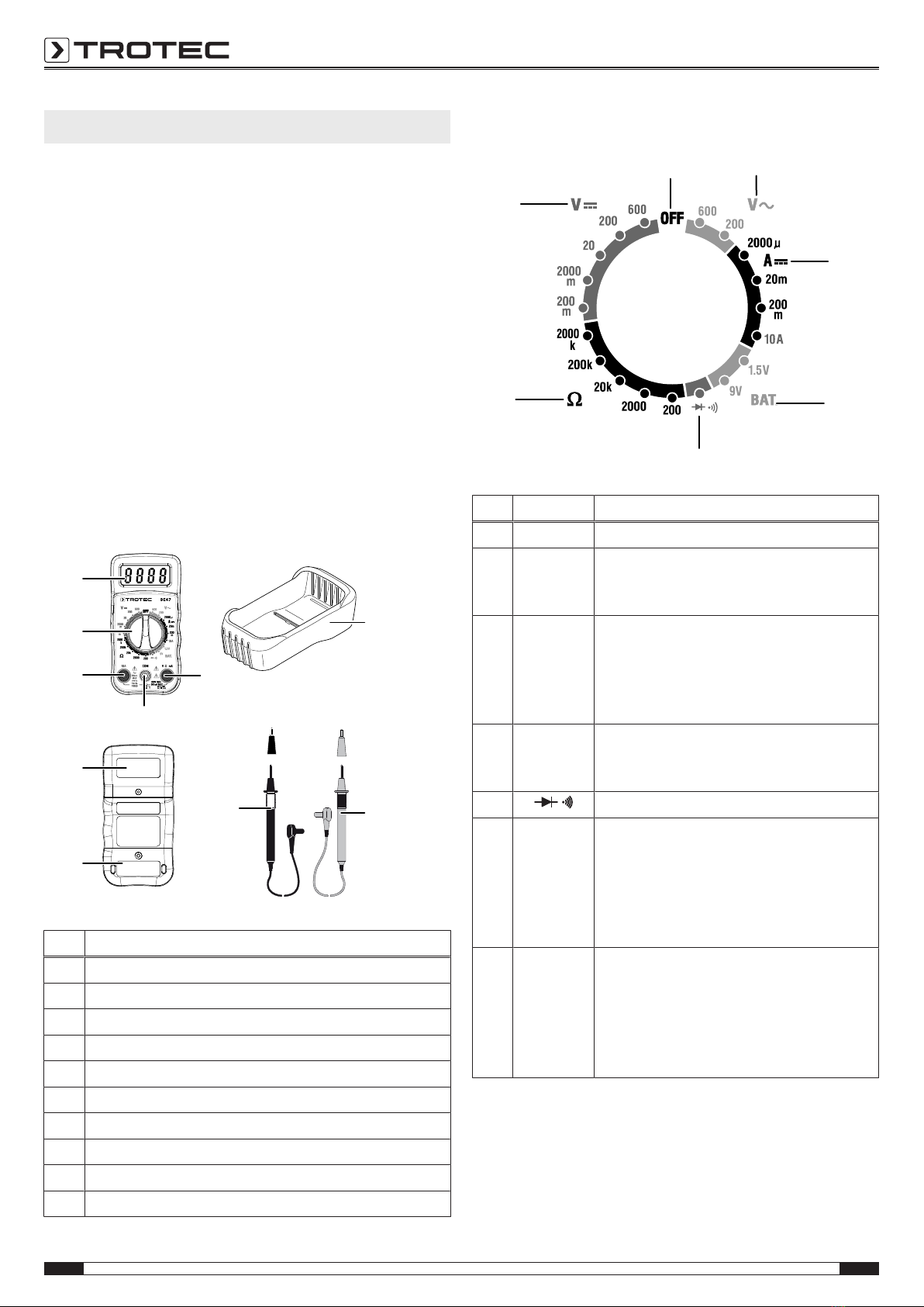
Trotec BE47 User manual

TRT-BA-BE47-TC2015-22-001-EN
BE47
EN
OPERATING MANUAL
MULTIMETER

2 EN
multimeter BE47
Table of contents
Notes regarding the operating manual.................................2
Safety .....................................................................................2
Information about the device................................................4
Transport and storage...........................................................6
Operation ...............................................................................6
Maintenance and repair ........................................................9
Errors and faults....................................................................9
Disposal .................................................................................9
Notes regarding the operating manual
Symbols
Warning of electrical voltage
This symbol indicates dangers to the life and health of
persons due to electrical voltage.
Warning
This signal word indicates a hazard with an average
risk level which, if not avoided, can result in serious
injury or death.
Caution
This signal word indicates a hazard with a low risk
level which, if not avoided, can result in minor or
moderate injury.
Note
This signal word indicates important information (e.g.
material damage), but does not indicate hazards.
Info
Information marked with this symbol helps you to carry
out your tasks quickly and safely.
Follow the manual
Information marked with this symbol indicates that the
operating manual must be observed.
You can download the current version of the operating manual
and the EU declaration of conformity via the following link:
BE47
https://hub.trotec.com/?id=43017
Safety
Read this manual carefully before starting or using the
device. Always store the manual in the immediate vicinity
of the device or its site of use!
Warning
Read all safety warnings and all instructions.
Failure to follow the warnings and instructions may
result in electric shock, fire and/ or serious injury.
Save all warnings and instructions for future
reference.
This appliance can be used by children aged from
8years and above and persons with reduced physical,
sensory or mental capabilities or lack of experience
and knowledge if they have been given supervision or
instruction concerning use of the appliance in a safe
way and understand the hazards involved.
Children shall not play with the appliance. Cleaning and
user maintenance shall not be made by children
without supervision.
• The device is supplied with a warning sign. Prior to initial
start-up, make sure to paste the corresponding warning
sign in your local language over the one present at the rear
of the device as described in chapter Operation.
• Do not use the device in potentially explosive rooms.
• Do not use the device in aggressive atmosphere.
• Protect the device from permanent direct sunlight.
• Do not remove any safety signs, stickers or labels from the
device. Keep all safety signs, stickers and labels in legible
condition.
• Do not open the device with a tool.
• Observe the storage and operating conditions as given in
the Technical data chapter.

EN 3
multimeter BE47
Intended use
Only use the multimeter for measuring voltage, current or
resistance whilst adhering to the technical data.
To use the device for its intended use, only use accessories and
spare parts which have been approved by Trotec.
Improper use
Do not use the device in potentially explosive atmospheres,
when wet or very humid.
Unauthorized modifications of the device are forbidden.
Personnel qualifications
People who use this device must:
• be aware of the dangers that occur when working with
electric devices in damp areas.
• take measures to protect themselves from direct contact
with live parts.
• have read and understood the operating manual, especially
the Safety chapter.
Residual risks
Danger
Electric shock from insufficient insulation. Check the
device for damages and proper functioning before each
use.
If you notice damages, no longer use the device.
Do not use the device when the device or your hands
are damp or wet!
Do not use the device when the battery compartment
or the housing are open.
Hazardous electric current
Work on the electrical components must only be
carried out by an electrically skilled person or an
authorised specialist company.
Danger
Electric shock from contact with live parts. Do not
touch any live parts. Secure neighbouring live parts by
insulating them or switching them off.
Warning
Risk of suffocation!
Do not leave the packaging lying around. Children may
use it as a dangerous toy.
Warning
The device is not a toy and does not belong in the
hands of children.
Warning
Dangers can occur at the device when it is used by
untrained people in an unprofessional or improper way!
Observe the personnel qualifications!
Caution
Keep a sufficient distance from heat sources.
Note
To avoid damages to the device, make sure that the
correct measuring range is selected before carrying out
a measurement.
If you are unsure, select the largest measuring range.
Unplug the cable before changing the measuring
range.
Note
To prevent damages to the device, do not expose it to
extreme temperatures, extreme humidity or moisture.
Note
Do not use abrasive cleaners or solvents to clean the
device.

4 EN
multimeter BE47
Information about the device
Device description
The multimeter is a battery-powered, mobile hand-held
measuring device with an extensive range of measurement
possibilities.
It features the following functional properties and equipment:
• Manual range selection
• 2000 count LC display
• Safety category CATII 600V/ CATIII 300V
• AC and DC voltage measurement
• Direct current measurement
• Resistance measurement
• Diode testing function
• Acoustic continuity testing
Device depiction
1
2
3
6
7
8
9
10
4
5
No. Designation
1 Protective cover
2 Red measuring probe
3 Black measuring probe
4 Fuses
5 Battery compartment
6 V/Ω/mA connection socket
7 COM socket
8 10 A socket
9 Rotary switch
10 LC display
Rotary switch
11 12
13
14
15
16
17
No. Position Description
11 OFF The device is switched off.
12 VAC AC voltage:
up to 600 VAC
up to 200 VAC
13 ADC Direct current:
up to 2000µA
up to 20 mA
up to 200 mA
up to 10 A
14 BAT. Battery voltage:
up to 1.5 V
up to 9 V
15 Diode test / continuity measurement
16 ΩResistance measurement:
up to 200 Ω
up to 2000 Ω
up to 20 kΩ
up to 200 kΩ
up to 2000 kΩ
17 VDC DC voltage:
up to 200 mVDC
up to 2000 mVDC
up to 20 VDC
up to 200 VDC
up to 600 VDC

EN 5
multimeter BE47
Technical data
General characteristics
Parameter Value
Diode test Max. testing current of 1 mA, open-
circuit voltage of 2.8 V DC (typically)
Continuity test Acoustic signal is emitted if the
resistance is less than 30Ω
Battery testing current 9 V (6 mA); 1.5 V (100 mA)
Input impedance >1 MΩ
V AC range 45 Hz to 450 Hz
A DC voltage drop 200 mV
LC display 3 ½ digits, 2000 count LCD, 0.5 inch
digits
Overload OL will be displayed
Polarity Automatic (no indication for positive);
minus (-) sign for negative
Measuring speed 2 x per second, nominal
Battery indicator BAT is indicated if the battery voltage
drops below the operating voltage
threshold
Battery 9 V monobloc battery
Fuses mA, µA range: 0.5 A/600 V (fast
acting)
A range: 10 A/600 V (fast acting)
Operating temperature 0°C to 50°C (32°F to 122°F)
Storage temperature -20°C to 60°C (-4°F to 140°F)
Relative humidity Operation: <70%
Storage: <80%
Operating height above
sea level
Maximum 2000 m (7000ft)
Weight 260g (9.17 oz.)
Dimensions 121.5 x 60.6 x 40 mm
(4.78" x 2.38" x 1.57")
Safety This measuring device is designed for
indoor use and complies with
overvoltage category CATII600V/
CATIII300V, pollution level2.
Measuring ranges
Function Measur-
ing range
Resolution Accuracy
DC voltage
(V DC)
200 mV 0.1 mV ± (0.5% +
2digits)
2000 mV 1 mV
20 V 0.01 V
200 V 0.1 V ± (1.0% +
2digits)
600 V 1 V
AC voltage
(V AC, 50 / 60 Hz)
200 V 0.1V ± (1.2% +
2digits)
600 V 1 V
Direct current
(A DC)
2000 µA 1 µA ± (1.0% +
2digits)
20 mA 10 µA
200 mA 100 µA ± (1.2% +
2digits)
10 A 10 mA ± (2.0% +
2digits)
Resistance
(Ω)
200 Ω 0.1 Ω ± (0.8% +
2digits)
2000 Ω 1 Ω
20 kΩ 0.01 kΩ
200 kΩ 0.1 kΩ
2000 kΩ 1 kΩ ± (1.0% +
2digits)
Battery test 9 V 10 mV ± (1.0% +
2digits)
1.5 V 1.0 mV
Note:
The accuracy is based on an ambient temperature of 18°C to
28°C and a relative humidity of less than 75%.
The accuracy specification consists of two values:
• % value referring to read value: Corresponds to the
accuracy of the structure to be measured.
• + digits: Corresponds to the accuracy referring to the
analogue to digital converter.
Scope of delivery
• 1xMultimeter
• 1 x Safety measuring lines with test probes
• 1 x 9 V monobloc battery
• 1 x Getting started guide

6 EN
multimeter BE47
Transport and storage
Note
If you store or transport the device improperly, the
device may be damaged.
Note the information regarding transport and storage of
the device.
Transport
For transporting the device use a suitable bag to protect it from
external influences.
Storage
When the device is not being used, observe the following
storage conditions:
• dry and protected from frost and heat
• protected from dust and direct sunlight
• with a cover to protect it from invasive dust if necessary
• The storage temperature is the same as the range given in
the Technical data chapter.
• Remove the batteries from the device.
Operation
Inserting the battery
Insert the battery before first use.
Danger
Disconnect the measuring probes from the device
before opening the battery compartment.
Note
Make sure that the surface of the device is dry and the
device is switched off.
1. Remove the protective cover(1) from the device.
2. Loosen the screw at the battery compartment(5).
3. Open the battery compartment.
4. Connect the battery to the battery clip with correct polarity.
5. Insert the battery with the battery clip into the battery
compartment.
6. Close the battery compartment and retighten the screw.
7. Place the device back into the protective cover.
Attaching the warning sign
Prior to initial start-up, check whether the warning sign at the
rear of the device is in your local language, if not, paste the
proper one over it. A warning sign in your native language is
supplied along with the device. Please proceed as follows to
attach the warning sign to the rear of the device:
1. Remove the label in your local language from the supplied
film.
2. Stick the label on the intended position at the rear of the
device.

EN 7
multimeter BE47
Undefined displays
If measuring inputs are open or touched by hand, this can lead
to undefined displays. This is not a malfunction but a reaction of
the sensitive measuring input to existing interference voltages.
Normally, when there is no high interference level at the
workplace, and in case of a short circuit at the measuring input,
zero is displayed immediately. If the measuring object is
connected, the exact measured value is displayed. Fluctuations
in the displayed value by some digits are systemic and within
the tolerance.
If the resistance measuring range, the continuity testing range
or the diode test was selected and the measuring input is open,
the overflow indicator will appear.
Measuring DC voltage
Danger
Improper handling of the measuring device entails a
risk of electric shock!
Before carrying out voltage measurements, observe the
following:
• Never apply a voltage exceeding the rated nominal voltage
of the measuring device between the connections, or
between the connections and ground (see imprint on
housing).
• Check the measuring lines for damaged insulation and for
continuity. Exchange damaged measuring lines.
• Check the insulation of the measuring device sockets.
• Before using the measuring device check its functionality
by carrying out measurements with a known voltage.
• First connect the measuring line connected to ground, and
only then connect the live measuring line. When
disconnecting the measuring lines, proceed in reverse
order, i.e. disconnect the live measuring line first.
• Prior to every voltage measurement make sure that the
measuring device is not set to the current measuring
range.
• If the device displays an overload (OL) immediately after
being connected to the measuring object, first switch off
the circuit at the measuring object and then immediately
remove the measuring lines from the measuring object.
• Do not switch any motors in the measuring circuit on or off
during a measurement. Voltage peaks caused by switch-
on and switch-off can damage the measuring device.
1. Select the largest VDC voltage measuring range using the
rotary switch.
2. Insert the plug of the black measuring line into the COM
measuring socket and the plug of the red measuring line
into the V/Ω/mA measuring socket.
3. Connect both measuring tips to the measuring object with
correct polarity (black to minus, red to plus).
ðIf the input voltage is negative, a minus (-) will appear in
front of the measured value on the display.
ðThe measured value is shown on the display.
4. Turn the rotary switch to the position that is the closest to
the indicated value but does not fall below it.
ðThe measured value is shown on the display.
Measuring AC voltage
Danger
Improper handling of the measuring device entails a
risk of electric shock!
Before carrying out voltage measurements, observe the
following:
• Never apply a voltage exceeding the rated nominal voltage
of the measuring device between the connections, or
between the connections and ground (see imprint on
housing).
• Check the measuring lines for damaged insulation and for
continuity. Exchange damaged measuring lines.
• Check the insulation of the measuring device sockets.
• Before using the measuring device check its functionality
by carrying out measurements with a known voltage.
• First connect the measuring line connected to ground, and
only then connect the live measuring line. When
disconnecting the measuring lines, proceed in reverse
order, i.e. disconnect the live measuring line first.
• Prior to every voltage measurement make sure that the
measuring device is not set to the current measuring
range.
• If the device displays an overload (OL) immediately after
being connected to the measuring object, first switch off
the circuit at the measuring object and then immediately
remove the measuring lines from the measuring object.
• Do not switch any motors in the measuring circuit on or off
during a measurement. Voltage peaks caused by switch-
on and switch-off can damage the measuring device.
1. Select the desired VAC voltage measuring range using the
rotary switch.
2. Insert the plug of the black measuring line into the COM
measuring socket and the plug of the red measuring line
into the V/Ω/mA measuring socket.
3. Connect both measuring tips to the measuring object with
correct polarity (black to minus, red to plus).
ðIf the input voltage is negative, a minus (-) will appear in
front of the measured value on the display.
ðThe measured value is shown on the display.
4. Turn the rotary switch to the position that is the closest to
the indicated value but does not fall below it.
ðThe measured value is shown on the display.

8 EN
multimeter BE47
Measuring direct current
Danger
Improper handling of the measuring device entails a
risk of electric shock!
Observe the following prior to every current measurement:
• Before connecting a measuring device to an electric
circuit, cut off the circuit current. Discharge the capacitors.
• For measuring the current, interrupt the circuit to be
checked and connect the measuring device in series with
the consumer in this circuit.
• Never connect a voltage source to the multimeter's
measuring sockets when a current measuring range is
selected. The device can be damaged.
• The voltage in the measuring circuit must not be higher
than 600V (CATIII) to ground.
• When measuring stronger currents from 400mA in the
10A range, the duration of a measurement must not
exceed 30s. Otherwise, the device may be damaged due
to excessive heating.
1. Depending on the expected measuring current, select the
μA, mA or 10A range using the rotary switch.
2. Insert the plug of the black measuring line into the COM
measuring socket and the plug of the red measuring line
into the mA or 10A measuring socket, depending on the
selected range.
3. Switch off the voltage supply at the measuring object and
connect the measuring tips to the measuring object with
correct polarity (in series; red to plus, black to minus).
4. Switch the measuring circuit back on and read the
measured value from the display.
Note:
If you have selected the 10A range for safety's sake, but the
measuring current is less than 400mA, switch the measuring
circuit off again. Plug the red measuring line into the mA socket
and select a measuring range in the mA range. Switch the
measuring circuit back on.
Measuring resistance
Danger
Before carrying out resistance, continuity or diode
measurements, switch off the current of the electric
circuit and discharge all capacitors.
1. Select the largest resistance measuring range (Ω) using the
rotary switch.
2. Insert the plug of the red measuring line into the V/Ω/mA
measuring socket and the plug of the black measuring line
into the COM measuring socket.
3. Connect the measuring lines to the measuring object.
When measuring in the highest measuring range, the
measuring device may take some time to display a stable
value. This is due to the measuring principle and not a
malfunction.
ðThe measured value is shown on the display.
4. Turn the rotary switch to the position that is the closest to
the indicated value but does not fall below it.
ðThe measured value is shown on the display.
Continuity test
Danger
Before carrying out resistance, continuity or diode
measurements, switch off the current of the electric
circuit and discharge all capacitors.
1. Set the rotary switch to position .
2. Insert the plug of the red measuring line into the V/Ω/mA
measuring socket and the plug of the black measuring line
into the COM measuring socket.
3. Connect the measuring lines to the circuit to be tested.
ðWhen the circuit is closed and the resistance is smaller
than 30Ω, an acoustic signal is emitted.
ðWhen the circuit is open, OL is displayed.
Diode test
This function allows to check semiconductor paths for continuity
and blocking function.
1. Set the rotary switch to position .
2. Insert the plug of the red measuring line into the V/Ω/mA
measuring socket and the plug of the black measuring line
into the COM measuring socket.
3. Connect the measuring lines to the diode.
ðA measured value between 400mV and 700mV
indicates a forward direction of the diode.
ðIf the measured value is 1, the diode is blocking.
ðIf OL is displayed with both polarities, the circuit is not
closed.
ðMeasured values near 0V indicate a short circuit in the
circuit.

EN 9
multimeter BE47
Battery test
Danger
Do not test batteries while they are installed in the
devices. The batteries must be removed before tests
can be carried out.
1. Turn the function switch to 1.5 V or 9 V BAT. Use the
1.5Vposition for "AAA", "AA", "C", "D" and other
1.5Vbatteries. Use the 9Vposition for rectangular
9Vmonobloc batteries.
2. Insert the plug of the red measuring line into the V/Ω/mA
measuring socket and the plug of the black measuring line
into the COM measuring socket.
3. Apply the black test probe to the negative side of the
battery. Apply the red test probe to the positive side of the
battery.
ðThe measured value is shown on the display.
Battery type Good Low Poor
1.5Vbattery >1.35 V 1.22 to 1.35 V <1.22 V
9Vbattery >8.2 V 7.2 to 8.2 V <7.2 V
Maintenance and repair
Battery change
A battery change is required when the battery status indication
flashes or the device can no longer be switched on (see chapter
Inserting the batteries).
Cleaning
Clean the device with a soft, damp and lint-free cloth. Make
sure that no moisture enters the housing. Do not use any
sprays, solvents, alcohol-based cleaning agents or abrasive
cleaners, but only clean water to moisten the cloth.
Repair
Do not modify the device or install any spare parts. For repairs
or device testing, contact the manufacturer.
Errors and faults
The device has been checked for proper functioning several
times during production. If malfunctions occur nonetheless,
check the device according to the following list.
Display segments are only faintly visible or flicker:
• The battery voltage is too low. Exchange the batteries
immediately.
The device displays implausible measured values:
• The battery voltage is too low. Exchange the batteries
immediately.
Disposal
The icon with the crossed-out waste bin on waste
electrical or electronic equipment stipulates that this equipment
must not be disposed of with the household waste at the end of
its life. You will find collection points for free return of waste
electrical and electronic equipment in your vicinity. The
addresses can be obtained from your municipality or local
administration. For further return options provided by us please
refer to our website www.trotec24.com.
The separate collection of waste electrical and electronic
equipment aims to enable the re-use, recycling and other forms
of recovery of waste equipment as well as to prevent negative
effects for the environment and human health caused by the
disposal of hazardous substances potentially contained in the
equipment.
Li-Ion
In the European Union, batteries and accumulators must not be
treated as domestic waste, but must be disposed of
professionally in accordance with Directive 2006/66/EC of the
European Parliament and of the Council of 6September 2006
on batteries and accumulators. Please dispose of batteries and
accumulators according to the relevant legal requirements.

Trotec GmbH & Co. KG
Grebbener Str. 7
D-52525 Heinsberg
+49 2452 962-400
+49 2452 962-200
www.trotec.com
Other manuals for BE47
2
Table of contents
Other Trotec Multimeter manuals