TEXIO IF-60RU User manual

取扱説明書
インタフェイスユニット
IF-60RU IF-60GP
B71-0011-00
この取扱説明書では、当社製電源 PSF シリーズ用のインタフェイスユニット IF-60RU、IF-60GP の取り付け方法について説
明します。インタフェイスユニットを組み込んだ電源の使用方法については電源本体の取扱説明書をご覧ください。
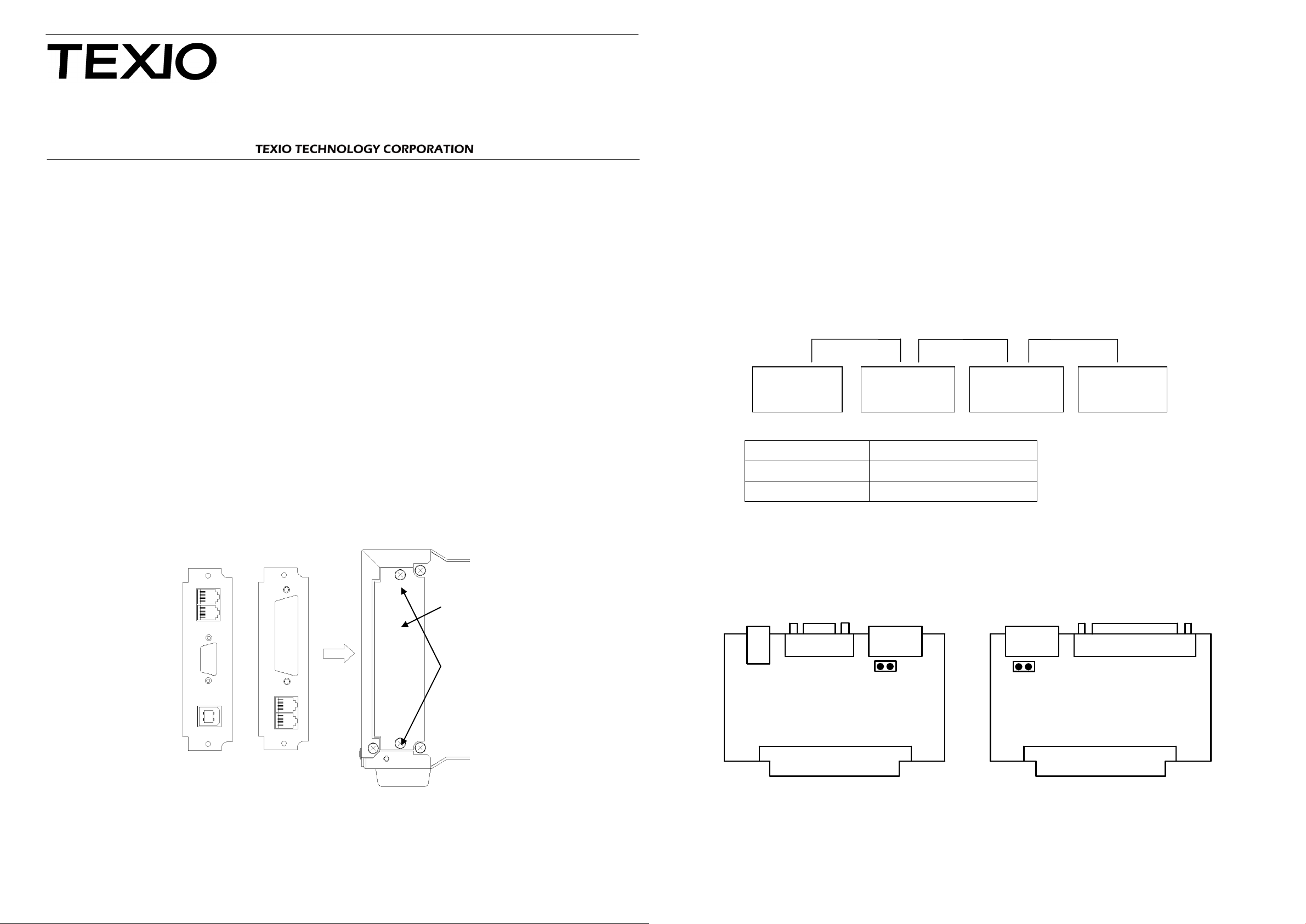
1. インタフェイスユニットの取り付け方法
インタフェイスボードを取り付ける場合、下記の手順に沿って十分に注意して作業してください。
(1) 電源本体の AC コードを取り外して電源スイッチがオフの状態で表示部がすべてが消えていることを確認します。
(2) 本体背面のブランクパネル①を止めている 2本のネジ②を取り外してブランクパネルを取り外します。
(3) インタフェイスユニットの向きに注意してスロットに沿って挿入してください。
注)作業中に電源内部に異物が入らないようにしてください。内部に異物が入ってしまった場合は絶対に電源を
ON にしないでください
(4) 正しい位置にインタフェイスユニットが装着されていない場合はネジ位置が合っていませんので再度やり直してください。
(5) 最後にブランクパネルを止めていたネジでインタフェイスユニットをネジ止めします。
(6) AC コードをつけた後に電源をいれ表示部にインタフェイスユニットのモデル名が表示されていれば組み込みは完了
です。
(7) 通信の設定方法や制御方法などは電源本体の取扱説明書をご覧ください。
2. インタフェイスユニットの取り外し方法
インタフェイスボードを取り付ける場合、下記の手順に沿って十分に注意して作業してください。
(1) 電源本体の AC コードを取り外して電源スイッチがオフの状態で表示部がすべてが消えていることを確認します。
(2) インタフェイスユニットを止めている 2本のネジ②を取り外してインタフェイスユニットを取り外します。
注)インタフェイスはしっかりコネクタにささっているために GP-IB または RS-232C のコネクタをさした状
態で作業すると容易にとりはずすことができます。
(3) ブランクパネルを 2本のネジ②で止めます。
注)作業中に電源内部に異物が入らないようにしてください。内部に異物が入ってしまった場合は絶対に電源を
ON にしないでください。
3. ローカルバスの終端設定
ローカルバスを利用する場合は、通信線のインピーダンス整合をとるために、通信経路の両端に終端抵抗を入れる必
要があります。終端抵抗はインタフェイスユニット上に用意してあり、ジャンパピン(CN2)のショート(ON)・オープン
(OFF)で切り換えることができます。通信経路の途中に終端抵抗が入っていたり、両端の終端がない場合は、動作が
不安定になりますのでご注意ください。
ショートコネクタを装着するジャンパピン(CN2)の位置は以下の場所にあります。インタフェイスユニットを購入した時点で
は、シュートコネクタがショートの状態で装着されていますので、中間に配置するインタフェイスユニットのショートコネクタを
取り除いてください。
取り除いたショートコネクタは故障の原因になりますので1ピンだけささった状態で電源本体に装着しないでください。
USB RS-232C LOCAL
BUS
CN2
IF-60RU
CN2
LOCAL
BUS GP-IB
IF-60GP
IF-60RU 正面図 IF-60GP 正面図
4. 使用方法
通信の設定方法や制御方法などは電源本体の取扱説明書をご覧ください。また各インタフェイスを利用する場合のサ
ンプルプログラムや USB で制御するためのデバイスドライバ・API を用意しております、弊社ホームページ
(www.texio.co.jp )からダウンロードしてご利用ください。
終端抵抗
ショートコネクタ(CN2)
あり
あり
なし
なし
IF-60GP
終端:ON
IF-60GP
終端:OFF
IF-60GP
終端:OFF
IF-60GP
終端:ON
ローカルバス通信経路
IF-60RU
取り付け方向
IF-60GP
取り付け方向
①ブランクパネル
②取付けネジ
本体背面インタフェイススロット部
INSTRUCTION MANUAL
INTERFACE UNITS
IF-60RU IF-60GP
B71-0011-00
This instruction manual describes the procedures of installing the Interface Unit IF-60RU or IF-60GPfor our PSF Series
Power Supply Units. Refer to the instruction manual of the PSF series power supply unit for the usage of the PSF
series with the interface unit built in.
1. Installing the Interface Unit
Follow the instructions shown below and install the interface board properly with great care.
(1) Disconnect the AC power cable from the power supply unit. Make sure that the power switch is set to the Off
position and all display units are off.
(2) Remove two screws ②from the blank panel ①on the rear panel of the power supply unit, and detach the blank
panel.
(3) Insert the interface unit into the slot with care in the proper direction.
NOTE: Do not put any objects into the power supply unit during installation of the interface unit. Never turn on the
power supply unit if some objects should enter it.
(4) If the interface unit is not installed at the proper position, the screw positions are incorrect. Retry installation from
the beginning.
(5) Fix the interface unit with the screws removed from the blank panel in step (2).
(6) Connect the AC power cable, turn on the power supply unit, and check if the model name of the interface unit is
displayed. The interface unit is installed properly if its model name is displayed.
(7) Refer to the instruction manual of the PSF series power supply unit for the normal setting and control procedures.
2. Uninstalling the Interface Unit
Follow the instructions shown below and uninstall the interface board properly with great care.
(1) Disconnect the AC power cable from the power supply unit. Make sure that the power switch is set to the Off
position and all display units are off.
(2) Remove two setscrews ②from the interface unit. Uninstall the interface unit.
NOTE: The interface unit is plugged in the connector firmly. It may be uninstalled easily with the GP-IB or
RS-232C connector plugged with the unit.
3. Setting Local Bus Termination
When a local bus is used, it is necessary to connect termination resistors with both ends of the communication path
for impedance matching of the communication lines. The interface unit has termination resistors, which may be
selected by short-circuiting (ON) or opening (OFF) the jumper pin (CN2). Note that operation may become
unstable if there are termination resistors are in the middle of the communication path or no termination resistors
are connected with both ends of the communication path.
The jumper pin (CN2) for the shorting connector is located in the position shown below. The shorting connector is in
the short-circuit condition at the time when the interface unit is installed. Remove the shorting connector from the
interface unit installed in the center.
The removed shorting connector may cause an error. Do not mount in the power supply unit in the condition where
a single pin is connected.
USB RS-232C LOCAL
BUS
CN2
IF-60RU
CN2
LOCAL
BUS GP-IB
IF-60GP
Front view of IF-60RU Front view of IF-60GP
4. Usage
Refer to the instruction manual of the PSF series power supply unit for the normal setting and control procedures.
The sample programs for using the interface as well as the device driver and API for USB control are available online.
Download them from the our homepage (www.texio.co.jp).
Termination resistor
Shorting connector (CN2)
Provided.
Provided.
Not provided.
-
IF-60GP
Terminator:ON
IF-60GP
Terminator:OFF
IF-60GP
Terminator:OFF
IF-60GP
Terminator:ON
IF-60RU
IF-60GP
①Blank panel
②Setscrews
Interface slot of power supply unit
Installation direction
Local Bus Communication Path
This manual suits for next models
1
Other TEXIO Recording Equipment manuals


