TEXIO IF-71RS User manual
この取扱説明書では、当社製電源 PS-A シリーズ、PDS-A シリーズのインタフェ-スユニット IF-71RS、
IF-70GU、IF-71LU、IF-70PS の取付け方法について説明します。インタフェ-スユニットを組込んだ PS-A 電
源および PDS-A 電源の使用方法については電源本体の取扱説明書をご覧ください。
・PS-A/PDS-A 電源には、標準でアナログコントロールユニット(以下、標準ボードという)が装着されています。
他の IF ユニットを装着する時は、下記の手順で取外し、取付けをおこなってください。
・IF-70GU、IF-71LUは動作設定をインタフェースユニット上にショートピンを挿して行います、IF-71RSは
動作設定をディップスイッチとインタフェースユニット上にショートピンを挿して行います。
スロットにユニットを挿す前に動作設定をよく確認してください。
1. IF ユニットの取外し方
・本体背面の標準ボード用パネル(①)を止めている 2本の取付けネジ(②)を外し、パネルを取外します。
・標準ボードを取外します。
標準ボードはコネクタにささっています、取外すときは、CN3 とSW1 のコネクタ間にあるユニットの穴にマイ
ナスドライバーなどを差込むと、簡単に取外すことができます。
・IF-71RS、IF-70GU、IF-71LU はパネル右側の中央部の切り欠き部(③)にマイナスドライバーなどを差込
むようにして、パネルを手前側に起すように取外します。
(注意) パネルが反る場合がありますので、パネルの上下等を持ちながら取外さないでください。
・IF-71RS、IF-70GU、IF-71LU は、GP-IB、RS-232C、LAN のコネクタを差込んだ状態で作業すると、簡単
に取外す事ができます。
・IF-70PS はユニットのネジ端子(④)を持ち取外します。
IF- 70GU IF-70PSIF-71RS IF-71LU
②取付けネジ
Setscrews
③切欠き
Cut out
①標準ボード用パネル
Analog control unit panel
④ネジ端子
Screw
Terminal
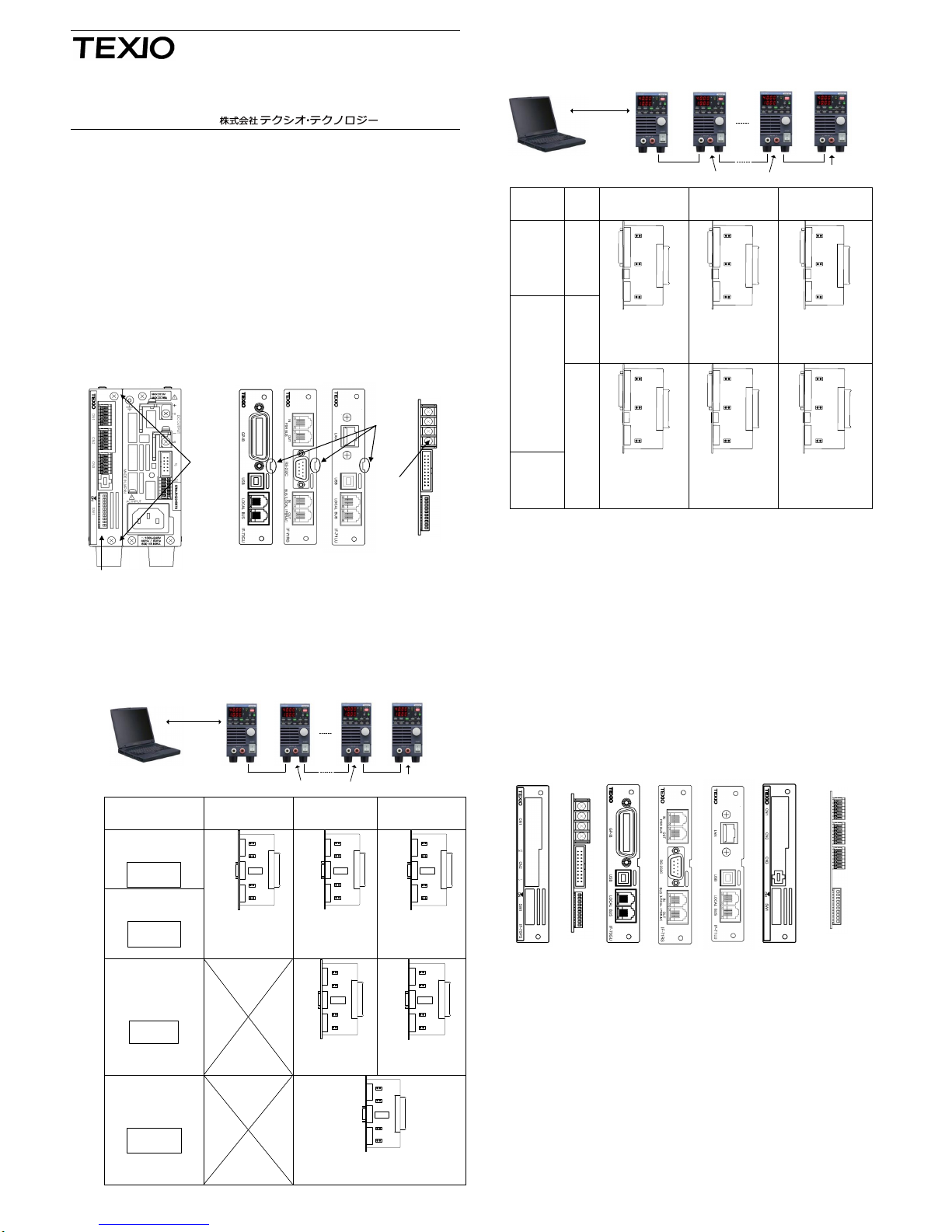
2.2 IF-71RSの設定
GP-IB
USB
RS-232C
LAN
MASTER
SYAD:1
SLAVE
SYAD:2
SLAVE
SYAD:n-1
SLAVE
SYAD:n
ローカルバス中間器 ローカルバス終端器
LocalBus LocalBus LocalBus
制御用PC
接続およびモード
マスター器設定
SYAD:1
ローカルバス
中間器設定
SYAD:2以上
ローカルバス
終端器設定
SYAD:2以上
PS-Aモード
(S2 1~6:ON )
(S2 7~8:OFF )
1 □■ O
2 □■ N
3 □■
4 □■
5 □■
6 □■
7 ■□
8 ■□
CN7
CN8
CN6
CN5
S2
▲
LOCAL
BUS
→
●
RS-232C
→
×
●
×
CN7
CN8
CN6
CN5
S2
▲
LOCAL
BUS
→
●
×
●
CN7
CN8
CN6
CN5
S2
▲
LOCAL
BUS
→
●
×
PDS互換モード
(S2 1~6:OFF )
(S2 7~8:ON)
1 ■□ O
2 ■□ N
3 ■□
4 ■□
5 ■□
6 ■□
7 □■
8 □■
(PDS-A のみ)
CN7:ジャンパあり●
CN6:ジャンパなし×
CN5:ジャンパあり●
CN7:ジャンパあり●
CN6:ジャンパなし×
CN5:ジャンパなし×
CN7:ジャンパあり●
CN6:ジャンパなし×
CN5:ジャンパあり●
PSR-M互換モード
(S2 1~6:ON)
(S2 7~8:OFF )
1 □■ O
2 □■ N
3 □■
4 □■
5 □■
6 □■
7 ■□
8 ■□
(PS-A のみ)
CN 7
CN8
CN 6
CN 5
S2
▲
PSR-M
BUS
→
●
●
×
CN7
CN8
CN6
CN5
S2
▲
●
PSR-M
BUS
→
●
●
CN7:ジャンパあり●
CN6:ジャンパあり●
CN5:ジャンパなし×
CN7:ジャンパあり●
CN6:ジャンパあり●
CN5:ジャンパあり●
PSR互換モード
(S2 1~6:ON)
(S2 7~8:OFF )
1 □■ O
2 □■ N
3 □■
4 □■
5 □■
6 □■
7 ■□
8 ■□
(PS-A のみ)
CN7
CN8
CN 6
CN 5
S2
▲
PSR
BUS
→
●
×
×
CN7:ジャンパなし×
CN6:ジャンパなし×
CN5:ジャンパあり●
▲CN8: 通常ジャンパあり、GND 切離時はジャンパなしとします。
2. IF ユニットの設定方法
2.1 IF-70GU および IF-71LU の設定
GP-IB
USB
RS-232C
LAN
MASTER
SYAD:1
SLAVE
SYAD:2
SLAVE
SYAD:n-1
SLAVE
SYAD:n
ローカルバス中間器 ローカルバス終端器
LocalBus LocalBus LocalBus
制御用PC
IF ユニット
PC
接続
マスター器設定
SYAD:1
PCAD:任意
ローカルバス
中間器設定
SYAD:2以上
ローカルバス
終端器設定
SYAD:2以上
IF-71LU
PDS-A のみ
LAN
CN2
CN4
CN3
▲
●
●
CN2
CN4
CN3
▲
●
×
CN2
CN4
CN3
▲
●
●
IF-70GU
GP-IB
CN4:ジャンパあり●
CN3:ジャンパあり●
CN4:ジャンパあり●
CN3:ジャンパなし×
CN4:ジャンパあり●
CN3:ジャンパあり●
USB
CN2
CN4
CN3
▲
●
×
CN2
CN4
CN3
▲
●
×
CN2
CN4
CN3
▲
●
●
IF-71LU
PDS-A のみ
CN4:ジャンパなし×
CN3:ジャンパあり●
CN4:ジャンパあり●
CN3:ジャンパなし×
CN4:ジャンパあり●
CN3:ジャンパあり●
▲CN2: 通常ジャンパあり、GND 切離時はジャンパなしとします。
3. IF ユニットの取付け方法
・本体に標準ボードやほかのインタフェースユニットが差込まれていない事を確認し、インタフェ-スユニット
の向きに注意してスロットにそって挿入してください。
(注意) 作業中に電源内部に異物が入らないようにしてください。内部に異物が入ってしまった場合は、
取除いてから電源を入れてください。本体の破損、感電の危険があります。
・正しい位置にインタフェ-スユニットが装着されていないとネジ位置が合いませんので注意してください。
(注意) IF-71RS、IF-70GU、IF-71LU は、ユニットとパネルが一体型になっております。
IF-70PS はユニットとパネルが別部品となります。
・パネルを止めていたネジでインタフェ-スユニットをネジ止めします。
IF-71LU
IF-70PS用
パネル IF- 70PS IF- 70GU 標準ボード用
パネル
標準ボード
IF-71RS
各ユニット・パネル取付方向
取扱説明書
インタフェ-スユニット
IF-71RS IF-70GU
IF-71LU IF-70PS
B71-0025-40
This instruction manual describes the procedures of installing the Interface Unit IF-71RS, IF-70GU, IF-71LU
or IF-70PS for PS-A /PDS-A Series. Refer to the instruction manual of the power supply unit for the usage of
the PS-A / PDS-A series with the interface unit built in.
- PS-A / PDS-A series power supply units are equipped with an analog control unit as a standard
feature.
To install other interface units, follow the instructions below to remove the existing one.
- Set the operation of IF-71RS / IF-70GU / IF-71LU by means of short pins and dipswitch on the
interface unit.
Carefully check the operation setting before inserting the unit into the slot.
1. Uninstalling the Interface Unit
-Remove two setscrews (②) from the analog control unit panel (①) on the rear side of the power
supply unit, and detach the panel.
- Uninstall the analog control unit.
The interface unit is plugged in the connector firmly. It can be uninstalled easily by inserting a slotted
screwdriver into the opening located between the CN3 and SW1 connectors.
- For IF-71RS / IF-70GU / IF-71LU, lift the panel toward you to detach it by inserting a slotted
screwdriver into the cut out located in themiddle on the right side of the panel.
NOTE: For IF-71RS / IF-70GU / IF-71LU, do not hold the top and bottom of the panel for
removing it. This may result in warpage of the panel.
- For IF-71RS and IF-70GU, the interface unit can be uninstalled easily with a GP-IB or RS-232C
connector mounted.
- For IF-70PS, hold the screw terminal (④) of the interface unit to uninstall it.
IF- 70GU IF-70PSIF-71RS IF-71LU
②取付けネジ
Setscrews
③切欠き
Cut out
①標準ボード用パネル
Analog control unit panel
④ネジ端子
Screw
Terminal
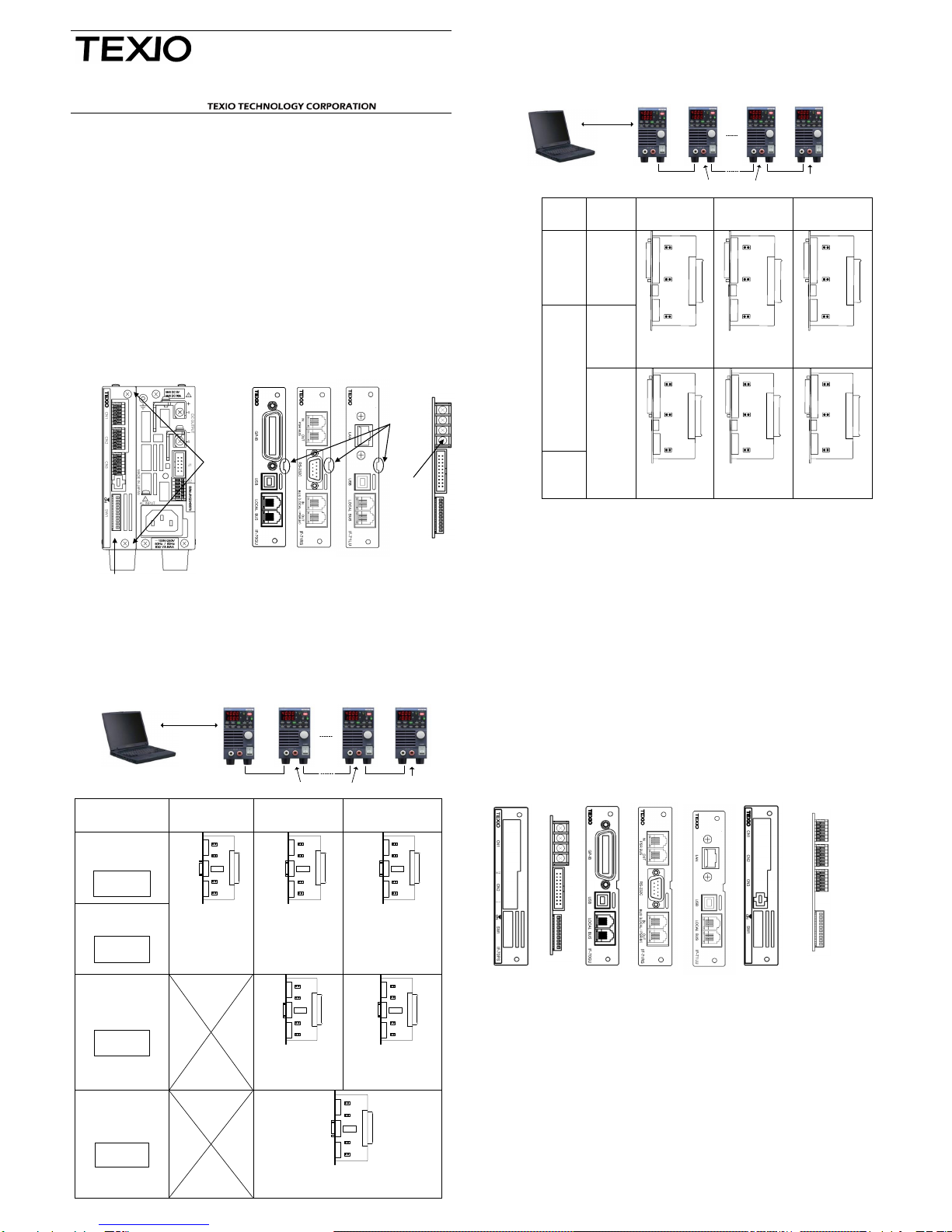
2.2 Setting forIF-71RS
GP-IB
USB
RS-232C
LAN
MASTER
SYAD:1
SLAVE
SYAD:2
SLAVE
SYAD:n-1
SLAVE
SYAD:n
Intermediate
of LocalBus
End of LocalBus
LocalBus LocalBus LocalBus
Control PC
Settings
Master
SYAD:1
Slave
Intermediate
SYAD:2 or more
Slave
End of LoacalBus
SYAD:2 or more
PS-A mode
(S2 1~6:ON)
(S2 7~8:OFF)
1 □■ O
2 □■ N
3 □■
4 □■
5 □■
6 □■
7 ■□
8 ■□
CN7
CN8
CN6
CN5
S2
▲
LOCAL
BUS
→
●
RS-232C
→
×
●
×
CN7
CN8
CN6
CN5
S2
▲
LOCAL
BUS
→
●
×
●
CN7
CN8
CN6
CN5
S2
▲
LOCAL
BUS
→
●
×
PDS mode
(S2 1~6:OFF)
(S2 7~8:ON)
1 ■□ O
2 ■□ N
3 ■□
4 ■□
5 ■□
6 ■□
7 □■
8 □■
(PDS-A only)
CN7:short ●
CN6:open ×
CN5:short ●
CN7:short ●
CN6:open ×
CN5:open ×
CN7:short ●
CN6:open ×
CN5:short ●
PSR-M mode
(S2 1~6:ON)
(S2 7~8:OFF)
1 □■ O
2 □■ N
3 □■
4 □■
5 □■
6 □■
7 ■□
8 ■□
(PS-A only)
CN 7
CN8
CN 6
CN 5
S2
▲
PSR-M
BUS
→
●
●
×
CN7
CN8
CN6
CN5
S2
▲
●
PSR-M
BUS
→
●
●
CN7:short ●
CN6:short ●
CN5:open ×
CN7:short ●
CN6:short ●
CN5:short ●
PSR mode
(S2 1~6:ON)
(S2 7~8:OFF)
1 □■ O
2 □■ N
3 □■
4 □■
5 □■
6 □■
7 ■□
8 ■□
(PS-A only)
CN7
CN8
CN 6
CN 5
S2
▲
PSR
BUS
→
●
×
×
CN7:open ×
CN6:open ×
CN5:short ●
▲CN8: Normally is short. Open to separate the frame GND and the signal GND.
2. Setting the Interface Unit
2.1 Setting for IF-70GU and IF-71LU
GP-IB
USB
RS-232C
LAN
MASTER
SYAD:1
SLAVE
SYAD:2
SLAVE
SYAD:n-1
SLAVE
SYAD:n
Intermediate
of LocalBus
End of LocalBus
LocalBus LocalBus LocalBus
Control PC
IF UNIT
PC
Connection
Master
SYAD:1
PCAD:any
Slave
Intermediate
SYAD:2 or more
Slave
End of LoacalBus
SYAD:2 or more
IF-71LU
(PSD-A)
LAN
CN2
CN4
CN3
▲
●
●
CN2
CN4
CN3
▲
●
×
CN2
CN4
CN3
▲
●
●
IF-70GU
GP-IB
CN4:short ●
CN3:short ●
CN4:short ●
CN3:open ×
CN4:short ●
CN3:short ●
USB
CN2
CN4
CN3
▲
●
×
CN2
CN4
CN3
▲
●
×
CN2
CN4
CN3
▲
●
●
IF-71LU
(PDS-A)
CN4:open ×
CN3:short ●
CN4:short ●
CN3:open ×
CN4:short ●
CN3:short ●
▲CN2: Normally is short. Open to separate the frame GND and the signal GND.
3. Installing the Interface Unit
- Make sure that the analog control unit or IF-70 series has not been mounted to the PS-A / PDS-A
power supply unit. Then, insert the interface unit into the slot in the correct direction.
NOTE: Do not put any objects into the power supply unit during installation of the
interface unit. If some objects should enter it, remove them before turning on the
power. Failure to do so may cause damage to the product or electric shock.
- If the interface unit is installed in an improper position, the screws cannot be positioned correctly.
NOTE: For IF-71RS / IF-70GU / IF-71LU, the unit is integrated with the panel; For IF-70PS,
the unit and the panel are separate.
- Fix the interface unit with the screws removed from the panel.
INSTRUCTION MANUAL
INTERFACE UNITS
IF-71RS IF-70GU
IF-71LU IF-70PS
B71-0025-40
IF
-
71
LU
IF
-
70
PS
Panel
IF
-
70
PS
Unit
IF
-
70
GU
Analog control
Panel
Analog control
U
nit
IF
-
71
RS
Installation direction
Unit
Unit
Unit
This manual suits for next models
3
Other TEXIO Recording Equipment manuals


