ELCODIS NT Series User manual


Notice:
OMRON products are manufactured for use according to proper procedures by a qualified operator
and only for the purposes described in this manual.
The following conventions are used to indicate and classify precautions in this manual. Always heed
the information provided with them. Failure to head precautions can result in injury to people or dam-
age to the product.
DANGER! Indicates informationthat,ifnotheeded,islikelytoresult inlossof lifeor serious
injury.
WARNING Indicates information that, if not heeded, could possibly result in loss of life or
serious injury.
Caution Indicatesinformationthat,ifnotheeded,could resultinrelativeseriousorminor
injury, damage to the product, or faulty operation.
OMRON Product References
All OMRON products are capitalized in this manual. The word “Unit” is also capitalized when it refers
to an OMRON product, regardless of whether or not it appears in the proper name of the product.
The abbreviation “Ch,” which appears in some displays and on some OMRON products, often means
“word” and is abbreviated “Wd” in documentation in this sense.
The abbreviation “PC” means Programmable Controller and is not used as an abbreviation for any-
thing else.
Visual Aids
The following headings appear in the left column of the manual to help you locate different types of
information.
Note Indicatesinformationof particular interestfor efficientandconvenientoperation
of the product.
1, 2, 3...
1. Indicates lists of one sort or another, such as procedures, checklists, etc.
OMRON, 1993
!
Downloaded from Elcodis.com electronic components distributor


! "# $
# %
&
"'(")
! "
& * + ,
*# - % ) .
% )
+/
&0 &
#
$ ! %
&
/& *#%
& *#% ) &
-% *#% ) & .
#% ! #&
, &
. 1# % & /& " % "
* & *#% & ,
$ * ) # &
2 * "# ,
* & /& ,
"
&%
* 3 ,
* 3 ,
& & 4% ! % 5% * 3 ,$
'% 3 .
&
'() %*
, - " /& & / % ") 2
, - " * "# 2
, - 2
Downloaded from Elcodis.com electronic components distributor

!! +
4 #
! ' '#
( .
* ( $.
- "# +
+ %
, - *
Downloaded from Elcodis.com electronic components distributor

.
About this Manual:
This manual describes the installation and operation of the NT-series Host Interface Unit Direct Connec-
tion and includes the sections described below.
Pleasereadthismanualcarefullyandbesureyouunderstandtheinformationprovidedbeforeattempting
to install and operate the NT-series Host Interface Unit Direct Connection.
WARNING Failure to read and understand the information provided in this manual may result in
personal injury or death, damage to the product, or product failure. Please read each
section in its entirety and be sure you understand the information provided in the section
and related sections before attempting any of the procedures or operations given.
Section 1
describes the role and operation of the Host Interface Unit, and its relationship to the PT fea-
tures and the new Direct Connection function.
Section 2
describes how to connect the Host Interface to the PT and the PT to the PC.
Section 3
describes the basic operation of the new Direct Connection function. Please read this section
carefully before using your PT. The Direct Connection function is extremely useful when a PT is used.
Section 4
describes the actual operation of the PT using Direct Connection. Only the allocated bits and
words are described related to the settings with the Support Tool.
Section 5
describes how to convert existing screen data for use with Direct Connection and how to con-
vert a PC program written for Direct Connection OFF for use with Direct Connection OMRON.
Section 6
describes the procedures to follow if the PT does not operate correctly.
Downloaded from Elcodis.com electronic components distributor

& % & % # & 6 % &# & % & /
*
( % "#
*#
"#
* + ,
! "# $
Downloaded from Elcodis.com electronic components distributor

1-1 Getting Starting
To ensure that the Host Interface Unit works correctly, carefully observe the fol-
lowing when positioning and handling it.
Location Do not install the Host Interface Unit in a location subject to the following condi-
tions:
•Dust, chemicals, or steam
•Severe temperature fluctuations
•High humidity and condensation
•Direct sunlight
•Strong electrical or magnetic fields
•Poor ventilation
•Severe vibration
Do not:
•Subject the Unit to strong shocks or vibrations
•Position the Unit’s PCB downward
•Touch the Unit’s PCB
•Put heavy objects on the unit
•Supply a voltage different from the specified voltage
Handling
Section 1-1
Downloaded from Elcodis.com electronic components distributor

System Configuration TheequipmentandpartsrequiredtoconfigurethesystemtousetheDirectCon-
nection function are shown below.
Programmable Terminal Screen-data
Memory Board/
Screen Memory
Host I/F Unit System ROM Support tools
NT20M Monochrome LCD:
NT20M-DT121-V2
Touch-panel Model
Screen Memory
SRAM/32 KB:
RAM22-15
SRAM/128 KB:
RAM13-10
Host Interface Unit
NT600M-LK201 NT20M-
SMR31-E NTM Support Tool
NT20M-ZASAT-EV4:
3.5-inch (2DD) and
5.25-inch (2HD) disks
Backlight replace-
able:
NT20M-DT131
Touch-panel Model
R
A
M
1
3
-
1
0
EPROM/64 KB:
ROM-KD-B
EPROM/128 KB:
ROM-13-12B
EEPROM/32 KB:
EER22-20
NT600M Monochrome LCD:
NT600M-DT122
Touch-panel Model
Screen-data
Memory Board
IC socket type:
NT600M-MP251
64-kbyteSRAM:
NT600M-MR641
128-kbyteSRAM:
NT600M-MR151
256-kbyteSRAM:
NT600M-MR251
Screen Memory
The screen
memory chip must
b
e
i
n
s
e
r
t
e
d
i
n
t
h
e
NT600M-
SMR31-E
EL display:
NT600M-DT211
Touch-panel Model
be inserted in the
IC socket. screen
dataiswrittenwith
aPROMwriter.
64-kbyte EPROM:
ROM-KD-B
128-kbyte
EPROM: ROM
13-12B
256-kbyte
EPROM: ROM
23-15B
32-kbye EEPROM:
EER22-20
1-2 Programmable Terminal
The OMRON Programmable Terminal (PT) displays the status and other in-
formation about the FA-applied factory. The PT is briefly described below.
1-2-1 Role and Operation
TheProgrammableTerminal(PT)isa FAfactoryterminaldevicewhichcommu-
nicates with Programmable Controllers (PCs) and displays the operating status
of machines and other equipment, work instructions, and operations of the PT.
Section 1-2
Downloaded from Elcodis.com electronic components distributor

#
The PT displays real-time information about the system and equipment operat-
ing status and manufactured quantity.
!
"
#
$%
%
&
'
$%&
(%) ($%%) (%*
$%&%
+,
Messages The PT warns of system or equipment errors with a display and buzzer, and
prompts the appropriate remedial action.
-. /
"!& 0 &
--
1
& 0 2
& " )&
& - " &
Setting touch switches on the PT allows workers to use the PT as an operating
panel. Production targets and other numeric data input to the PT can be trans-
mittedtothePC.
3
4
4
56(
4 4
56( 56(
Production Line Status
Monitoring
Panel Switch Functions
(Operation from the PT)
Section 1-2
Downloaded from Elcodis.com electronic components distributor

"
1-2-2 Displays ThePTcandisplaythefollowingitems toprovidetheoperationsmentionedpre-
viously. Each of these items is called a “display element.”
0 *
3
#
)
7&
($%%)8
% % %%
Character string
memory table
setting Text
Bar graph
Touch switches
Numeral
memory table
setting
Lamps
Text Characters which remain unchanged can be written directly as text.
Character strings stored in the character-string memory table are displayed.
The display can be changed by changing the data stored inthe character-string
memory table.
Numeral Memory Tables Numbersstoredinthenumeralmemorytablearedisplayed. Thedisplaycanbe
changed by changing the data stored in the numeral memory table.
The Direct Connection compatible Host Interface Unit also allows the display of
hexadecimal values.
Lamps Lampsaresquareorroundframeswhichindicatetheoperatingstatus.Theyare
controlledbythePC.Theycanbelit(highlighted)orflashed(intermittentnormal
and highlighted display).
Touch Switches Touch switches can be set anywhere on the screen. Touching the screen at a
touch switch location can switch the display (stand-alone function or display-
switch function) or notify the PC (notification function). The touch switches can
be lit or flashed by the PC in the same way as the lamps.
Bar Graphs The bargraph displays a comparison witha value stored inthe memory table. A
percentage value can be displayed simultaneously.
1-3 Host Interface Unit
The Host Interface Unit provides communication between the PT and PC. This
sections describestheoperationoftheHost InterfaceUnit andthenewlyadded
Direct Connection function.
Refer to
Section 3 Direct Connection Operation
and
Section 4 PT Operation
for
details on the Direct Connection function.
1-3-1 Operation Manycommunicationunitsareavailabletoprovidecommunicationbetweenthe
PTandPCfordifferentsystemconfigurations.TheHostInterfaceUnitisjustone
of the communication units which can be mounted on the PT. It can be con-
nected to the Host Link Unit or CPU of a C-series or CV/CVM-series PC.
The Host Interface Unit operates as an intermediary between the PT and PC. It
reads information to be displayed on the PT from the PC memory area and
writes it to the PT memory table, and writes information to the PC memory area
with the PT touch switches.
Character String Memory
Tables
Section 1-3
Downloaded from Elcodis.com electronic components distributor

&
The Host Interface Unit reads instructions to switch screens from the PC
memoryareaandcontrols thePT.ItreadsthestatusofthePTandwritesittothe
PC memory area.
Memory table
Touch switch
Screen switch
PT status
PT PC
Host
Interface
Unit Memory
area
1-3-2 Direct Connection Function
ThenewDirectConnectionfunctionhasbeenaddedtotheHostInterfaceUnitto
enable the reading and writing of PC bit and word data.
The Direct Connection function is described below.
•ThePTisabletodirectlyrefertoPCbitandworddatasothataPTcanbecon-
nectedtoaPCwithoutchangingthePCprogramcurrentlyrunningtheproduc-
tion line.
•The bits andwords referring to operatingstatus and work instruction informa-
tion and those storing input data can be freely allocated to almost any part of
thePCmemory.BitsandwordsinthePC canbereferencedfromanymemory
table.
•The area to control and notify the PT status, including display screens, back-
lighting on a flash control, alarms and buzzers, can be freely allocated to any
part of the PC memory.
Setting The Direct Connection functionis set usingthe NT-series SupportTool,which is
thenameof thesoftwareused tocreateandmaintainthedisplay datafor thePT
displays,memorytabledata,andmarkdata.Refertothemanuallistedbelowfor
informationontheSupportToolandhowitisused,aswellasforthesystemcon-
figuration:
NT20M/NT2000M/NT600M Support Tool Operation Manual (V004)
TheconventionalHostInterfaceUnitcommunicationprotocolis used.De-select
the Direct Connection function to use existing programs.
In this case, communication is with the PC’s DM area. Data in allother areas is
PCprogramdatawhichmustbesenttotheDMareainordertobetransmitted.In
addition, thenumberof numeral and character-string memory tables which can
be communicated with the PC is limited.
ThismanualdescribescommunicationsusingtheHostInterfaceUnitandDirect
Connection. Refer to
NT-series Host Interface Units Operation Manual (V003)
for information oncommunication without using the Direct Connection function.
PT PC
DM Area
AR Area
CIO Area
Timer/Counter
Area
Thenew Host Interface Unit DirectConnectionprotocolis used. DirectConnec-
tion allows direct reading and writing of most bits and words of the PC memory
and allows automatic changing of the display. This new communication format
Direct Connection is Not
Selected
Direct Connection is Set
Section 1-3
Downloaded from Elcodis.com electronic components distributor
%
reduces the load on the PC and increases the efficiency of program develop-
ment.
Refer to
Section 3 Direct Connection Operation
and
Section 4 PT Operation
for
details on the Direct Connection function.
PT PC
DM Area
AR Area
CIO Area
Timer/Counter
Area
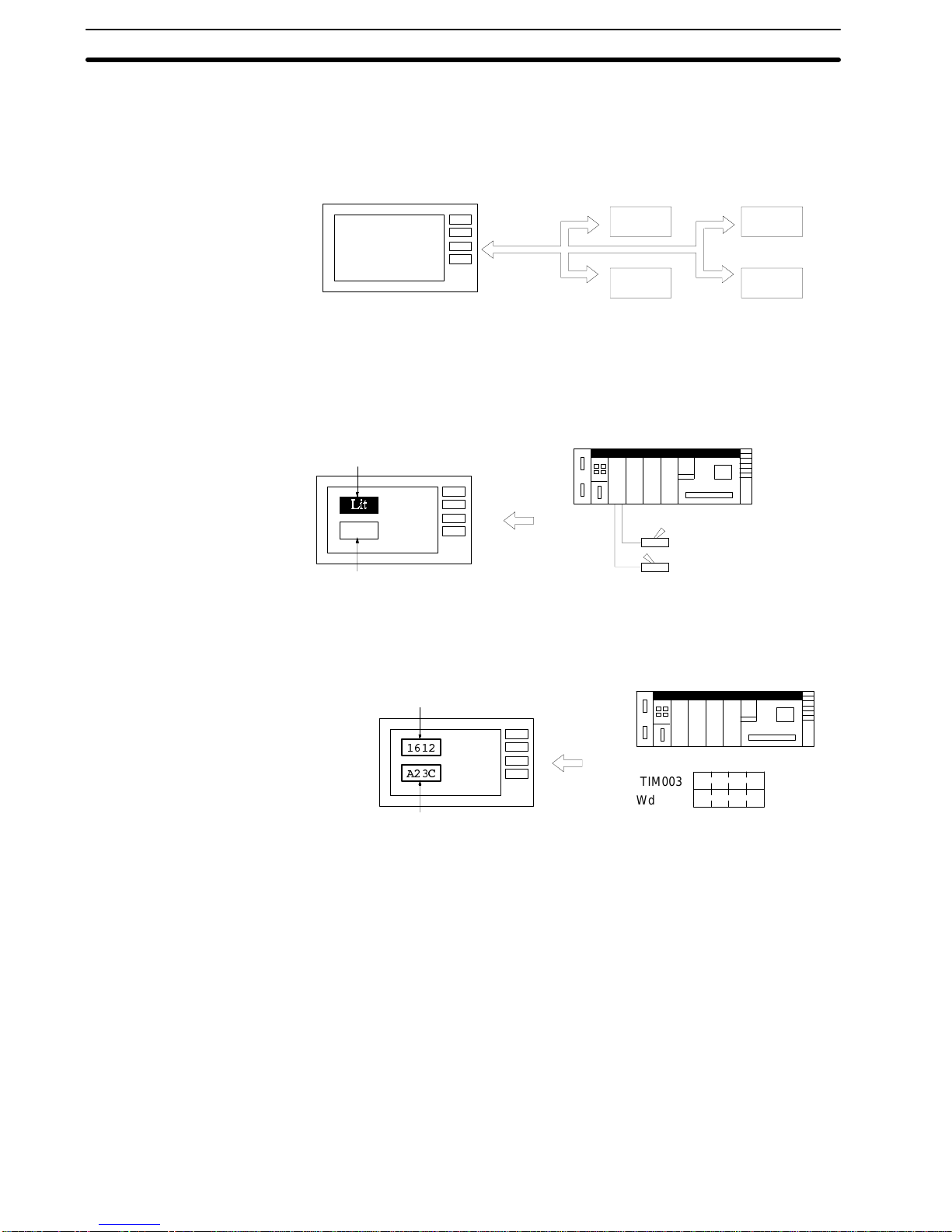
Examples are presented below of PT and PC operation when the Direct Con-
nection function is set.
Example 1
The status ofa PC bitcan be directly displayed as a PTlamp withoutusing a PC
program.
PT PC
Lamp 1 (Bit: 000100)
Lamp 2 (Bit: 000101)
Switch 1 ON (Bit: 000100)
Switch 2 OFF (Bit: 000101)
Not lit
Example 2
The displayed word can be freely selected for each memory table. The display
as a heraldically value makes it easy to monitor word contents.
PT PC
$
-
TIM003
Wd 0005
Numeral memory table 1 (TIM003)
Numeral memory table 150 (Wd 0005) A 2 3 C
1612
Direct Connection
Examples
Section 1-3
Downloaded from Elcodis.com electronic components distributor

+
1-4 System Configuration
This section shows the basic configuration of a system using a Host Interface
Unit. Refer to the individual equipment manuals for information on the equip-
ment used in the system.
Host Link Unit/CPU OMRON PC:
Controls the PT as required while controlling
machines and monitoring the production line.
RS-232C cable
(for Host Link Unit)
NT600M-LK201
Host Interface Unit
PT:
Provides display functions for monitoring
the production line and supporting the
operating environment. It notifies the PC
whenswitchesareturned ONorOFFand
of numerical inputs.
Computer (Support Tool):
Can be connected to the PT when
required to transfer prepared PT
screens and settings.
Support Tool
IBM PC/AT or
compatible
System Equipment and Software
OMRON PC General reference to a C-series or CV/CVM1-series PC.
AC
H-series or CV-series PC can be connected directly to the PT. A Host
Link Unit is required to connect a C-series PC.
Programmable Terminals NT20M, NT2000M, and NT600M.
Computer IBM PC/AT or compatible.
Support Tool NT20M/NT2000M/NT600M Support Tool Version 4.0
.
Connections Use an RS-232C cable to connect the PT to the PC. An RS-422 or optical-fiber
cable can be used with a Link Adapter.
Refer to the following chapters for details about connecting the PT to the PC.
RS-232C Cable
Section 2 Installation and Settings
RS-422 Cable
Appendix D RS-422 Connections
Optical Fiber Cable
Appendix E Optical Fiber Cable Connections
Section 1-4
Downloaded from Elcodis.com electronic components distributor

*
1-5 Before Operating
Follow the procedure indicatedbelow before operating aPT with Host Interface
Unit installed.
Support Tool
Check the PT power supply and
ground cable connections.
Install the Host Interface Unit.
Check settings and communica-
tions.
Create the PC program.
Check and set the PT and Host
Interface Unit.
Connection to the PC.
Transfer screen data
Create screens with the Support
Tool
Check and change the PC
settings.
Trial operation
Refer to page 35.
Refer to the
NT-series
Support Tool Operation
Manua
l.
Refer to the appropriate
PT Manual
PTPC
Refer to the appropriate
PC Manual
Refer to the appropriate
PC Manual
Refer to the appropriate
PT Manual
Refer to page 15.
Refer to page 14.
Refer to page 13.
Section 1-5
Downloaded from Elcodis.com electronic components distributor

/
Reference Manuals The NT20M/NT2000M Series and NT600M Series are covered in the six
manuals described below.
Name of Manual Contents Manual No.
NT20M/NT2000M Operation
Manual This manual provides specifications, functions, and operating
instructions for the NT20M and NT2000M Programmable Terminals. V001
NT600M Operation Manual This manual provides specifications, functions, and operating
instructions for NT600M Programmable Terminals. V002
NT-series Host Interface Unit
Operation Manual This manual covers the commands, controls, and communications
specifications for operating the NT20M and the NT600M. Refer to
this manual when programming host computer communications.
V003
NT20M/NT600M Support Tool
Operation Manual This manual covers methods for creating screens, including screen
data preparation, switches, lights, and alarms. V004
NT-series Host Interface Unit
Direct Connection Operation
Manual
This manual covers the Direct Connection feature which has been
added to the Host Interface Unit. V015
NT-series RS-232C/RS-422
Interface Unit Operation Manual This manual covers the commands, controls, and communications
specifications for operating the NT20M and the NT600M with the
RS-232C/RS-422 Interface Unit. Refer to this manual when
programming host computer communications.
V016
Section 1-5
Downloaded from Elcodis.com electronic components distributor

& % &/ & & % & &
# %
*# % + #
* /&
&
& /&
"'(")
#
& ,
/& .
Downloaded from Elcodis.com electronic components distributor

2-1 Components and Settings
The parts of the Host Interface and how to set the operating environment are
described below.
2-1-1 Description and Function of Components
The names and functions of the Host Interface parts are shown in the diagram
below.
NT600M-LK201 Host Interface
Host Interface front face
Switch cover
Open this cover to reveal the DIP switches
(SW4) which set the basic operation of the
Host Interface.
Host I/F RS-232C connector
for connection to the PC. Host Interface rear face
Unit connector for connection to the PT.
2-1-2 DIP Switch Settings
Set the operating environment with the Host Interface DIP switches (SW4) be-
fore installing the PT.
Set the Host Interface DIP switches in the positions shown below.
Switch cover The DIP switches are under the switch
cover on the front of the I/F Unit.
1234567890
SW4-3 to 4-6 and 4-0 Not used
Section 2-1
Downloaded from Elcodis.com electronic components distributor

SW4-1 Initializes the memory table allocating the words.
Setting Meaning Description
ON PT Initial values set by the Support Tool.
OFF PC The contents of the words allocated in the PC memory
are used as the memory table initial values.
SW4-2 Sets the PT Status Control Area and PT Status Notify Area in the General
Memory.
Setting Meaning Description
ON Add Add PT Status Control Area and PT Status Notify Area
to the general memory.
OFF Don’t add Do not add PT Status Control Area and PT Status Notify
Area to the general memory.
SW4-7, 8, 9 Sets the PT Baud Rate
SettheBaudRatetothesamevalueasthePCHostLinkfunctionbaudrateset-
ting.
Set the Baud Rate to the maximum value that both the PT and PC can handle.
Setting Baud Rate
SW4-7: ON
SW4-8, 9: OFF 4,800 bps
SW4-7, 9: ON
SW4-8: OFF 9,600 bps
SW4-7, 8: ON
SW4-9: OFF 19,200 bps
Note 1. Turn off the power supply before setting the operating environment with the
DIP switches.
2. Be sure to correctly set the communication conditions. Communication is
not possible if conditions are not set as shown above.
3. Use the cables recommended by OMRON to connect the units. Incorrect
communication may result if non-recommended cable types are used.
2-2 Installing the Host Interface
How to install the Host Interface in the PT.
2-2-1 Installation Turnthecut-out inthe Host InterfacetotheleftandpushtheUnit inuntil a“click”
is heard.
In difficult-to-connect situations move the Unit when connecting the Host Inter-
face.
Installation in the NT20M
NT20M
Rear face
Cut-out
Section 2-2
Downloaded from Elcodis.com electronic components distributor
This manual suits for next models
2
Other ELCODIS Recording Equipment manuals

Popular Recording Equipment manuals by other brands

Teac
Teac CD-RW880 Quick-start recording guide

Advance Tube Technology
Advance Tube Technology OP128 instruction manual

Ei Electronics
Ei Electronics EI944 instruction manual

Dantel
Dantel D18-05547 Series Installation & operation manual

Eventide
Eventide RIPTIDE Quick reference guide

Aviom
Aviom AN-16/i-m user guide


Yamaha
Yamaha TG77 operating manual

Emotiva
Emotiva RMC-1 user manual
 user manual")
Convergent Design
Convergent Design Odyssey7Q ProRes 422 (HQ) user manual

National Instruments
National Instruments ENET-232 Series user manual

Kannad
Kannad aviation CS144 Abbreviated component maintenance manual

Federal Signal Corporation
Federal Signal Corporation LSH-024 instruction sheet