Toslink 14524 User manual
1

2
CONTENTS
SAFETY WARNINGS AND GUIDELINES.......................................................................................................................................4
INTRODUCTION................................................................................................................................................................................................5
FEATURES..............................................................................................................................................................................................................6
PACKAGE CONTENTS.................................................................................................................................................................................6
PRODUCT OVERVIEW................................................................................................................................................................................. 7
Front Panel..................................................................................................................................................................................................... 7
Rear Panel....................................................................................................................................................................................................... 7
Keypad Controllers...............................................................................................................................................................................10
IR Remote Control.................................................................................................................................................................................12
LOCATION PLANNING .............................................................................................................................................................................13
CABLE PREPARATION...............................................................................................................................................................................14
Ethernet Cables.......................................................................................................................................................................................14
Speaker Wires...........................................................................................................................................................................................15
RCA Cables...................................................................................................................................................................................................15
3.5mm TRS Cables..................................................................................................................................................................................16
Mini Toslink® Cable...............................................................................................................................................................................16
Trigger Cables ...........................................................................................................................................................................................16
RS232 Serial Cable................................................................................................................................................................................. 17
IR Emitters .................................................................................................................................................................................................... 17
INSTALLATION................................................................................................................................................................................................18
Test Installation.......................................................................................................................................................................................18
Connecting Multiple Multizone Controllers..................................................................................................................18
Connecting the Wallplate Keypad Controllers...........................................................................................................19
Connecting External Amplifiers...............................................................................................................................................20
Connecting the Speaker Wires.................................................................................................................................................20

3
Connecting Analog RCA Source Devices.........................................................................................................................21
Connecting Analog 3.5mm Source Device......................................................................................................................21
Connecting a Digital Optical (S/PDIF) Source Device ..........................................................................................21
Connecting a Digital Audio Source Device...................................................................................................................22
Connecting the Triggers.................................................................................................................................................................22
Connecting IR Emitters....................................................................................................................................................................22
Connecting a Computer Using RS232 ................................................................................................................................23
Connecting Power...............................................................................................................................................................................23
Test Operation.........................................................................................................................................................................................23
Final Installation.....................................................................................................................................................................................25
RS232 SERIAL CONTROL........................................................................................................................................................................26
SPECIFICATIONS...........................................................................................................................................................................................32
REGULATORY COMPLIANCE............................................................................................................................................................. 33
Notice for FCC ......................................................................................................................................................................................... 33
Notice for Industry Canada..........................................................................................................................................................34

4
SAFETY WARNINGS AND GUIDELINES
This device is intended for indoor use only.
Do not expose this device to water or moisture of any kind. Do not place drinks or
other containers with moisture on or near the device. If moisture does get in or on
the device, immediately unplug it from the power outlet and allow it to fully dry
before reapplying power.
Do not touch the device, the power cord, or any other connected cables with wet
hands.
Do not expose this device to excessively high temperatures. Do not place it in, on,
or near heat sources, such as a fireplace, stove, radiator, etc. Do not leave it in direct
sunlight.
This device ventilates excessive heat through the slots and openings in the case. Do
not block or cover these openings. Ensure that the device is in an open area where
it can get sufficient airflow to keep from overheating.
Do not place or install this device in an area where it can be exposed to excessive
amounts of dust, humidity, oil, smoke, or combustible vapors.
Prior to operation, check the unit and power cord for physical damage. Do not use if
physical damage has occurred.
Take care to prevent damage to the power cord. Do not allow it to become
crimped, pinched, walked on, or become tangled with other cords. Ensure that the
power cord does not present a tripping hazard.
Before plugging the unit into a power outlet, ensure that the outlet provides the
same type and level of power required by the device.
This device uses a grounded power cord and requires a ground connection for safe
operation. Ensure that the power source has a proper ground connection. Do not
modify the plug or use a "cheater" plug to bypass the ground connection.
Ensure that power is turned off and disconnected before making any electrical
connections.

5
Disconnect the unit from the power source when replacing the fuse. Replace the
fuse only with the same type.
Unplug this device from the power source when not in use.
Never unplug the unit by pulling on the power cord. Always grasp the connector
head or adapter body.
Remove the batteries from the controller if it will go unused for a lengthy period of
time.
Clean using a soft, dry cloth only. Do not use chemical cleaners, solvents, or
detergents. For stubborn deposits, moisten the cloth with warm water.
This device has no user serviceable parts. Do not attempt to open, service, or
modify this device.
INTRODUCTION
Thank you for purchasing this Multizone Home Audio Controller and Amplifier Kit!
This device is a full function audio system, which combines the functions of a preamplifier,
a full 6x4 audio matrix, and four 70 watt power amplifiers for driving speakers in up to four
separate zones. Additionally, up to three multizone amplifiers, including the 10761 6x6 50-
watt model, can be combined to provide full signal switching and amplification to up to 16
different speaker zones!
For best results, please read and understand this manual thoroughly before installation,
paying particular attention to the safety warnings and guidelines. Keep this manual in a
safe place for future reference.

6
FEATURES
Two pairs of analog stereo RCA inputs
One analog 3.5mm TRS stereo input
One combination analog 3.5mm TRS/digital optical Mini Toslink® stereo input
Two RJ45 digital inputs for use with audio source devices, such as the model 13358
Multizone Source Keypad
Four separate stereo 70-watts per channel into 4-ohms audio amplifiers
Each amplifier can be bridged to produce 140-watts into an 8-ohm load
Can be expanded with up to two additional 6x4 or 6x6 multizone controllers
PA override feature to broadcast to all zones
12-volt triggers for each zone
Includes IR remote control and four remote keypad controllers
Includes rack mount ears for installation into a standard 19" equipment rack
PACKAGE CONTENTS
After receiving the product, please inventory the contents to ensure you have all the
proper parts, as listed below.
1x 6x4 multizone home audio controller/amplifier
4x Keypad controllers
1x Keypad in-wall hub connection plate
1x Infrared remote control
1x Expansion ribbon cable
1x Rack mounting kit
1x AC power cord (IEC 60320 C13 to NEMA 5-15)
1x User's manual
7
PRODUCT OVERVIEW
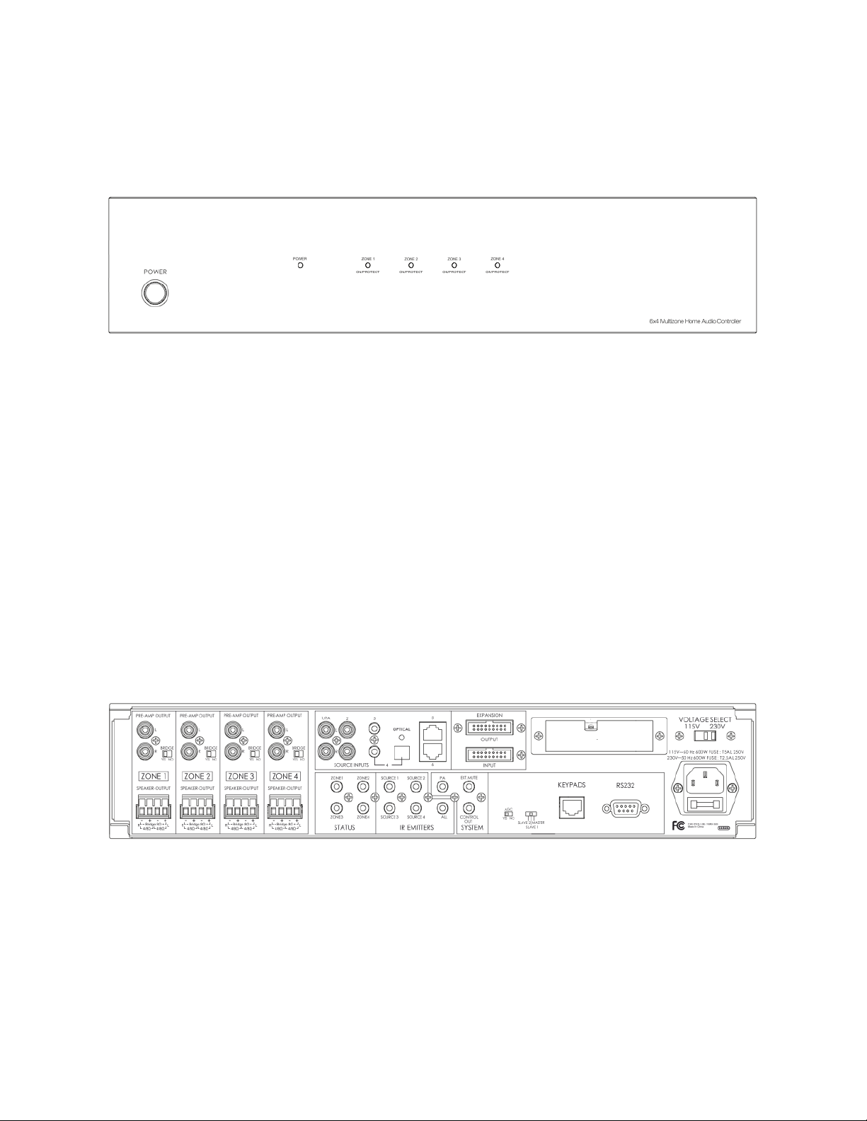
Front Panel
1. Power Button: Depress the power button to turn the controller/amplifier on or off.
Note that when the controller is powered on, each individual zone will remain in
standby until its keypad is activated.
2. Power LED Indicator: This LED is off when the controller is powered off and
illuminates red when power is applied.
3. Zone Status LED Indicators: These multicolor LEDs illuminate blue whenever the
individual zone keypad is activated. If the amplifier is driven into distortion, the
audio signal will cut off and the LED will change color to red, indicating that you
should immediately reduce the volume level using the zone keypad.
Rear Panel
4. Preamp Outputs: Each of these four stereo pairs of RCA jacks is used to connect to a
dedicated power amplifier, instead of using the built-in amplifier.
5. Bridge Switch: Each of these slide switches is used to switch the zone between
Stereo and Bridged Mono mode. In Stereo mode you can connect 4-ohm or 8-ohm
speakers, but in Bridged Mono mode you can only connect an 8-ohm load.

8
6. Speaker Output: Each of these removable Euroblock terminal blocks is used to
connect a pair of speakers in Stereo mode or a single speaker in Bridged Mono
mode.
7. Source Input 1: This analog stereo RCA pair is used to connect to the line level
output of an audio device, such as a CD player. When a 12VDC trigger signal is
detected on the
System PA
input, the audio on this input is broadcast to all zones.
8. Source Input 2: This analog stereo RCA pair is used to connect to the line level
output of an audio device, such as a CD player.
9. Source Input 3: This analog stereo 3.5mm TRS jack is used to connect to the line
level output of an audio device, such as a CD player, or the headphone output of a
mobile device.
10. Source Input 4: This 3.5mm TRS jack can be used as an analog stereo audio input or
as a digital optical S/PDIF (Mini Toslink®) input. Instead of requiring a physical switch
to change modes, the controller will automatically detect the type of signal and
adjust itself accordingly.
11. Source Inputs 5 and 6: Each of these RJ45 Ethernet jacks is used to connect to a
digital audio source, such as the model 13358 Multizone Source Keypad, using Cat5e
or Cat6 cables.
12. Zone Status: Each of these 3.5mm TS jacks provides a constant 12VDC signal output
whenever the corresponding zone is active. This 12-volt signal can be used as a
trigger for motorized devices, such as projector screens, curtains, lights, etc.
13. IR Emitters: Each of these 3.5mm TS jacks is used to connect to an infrared emitter,
which can repeat an IR control signal sent from a remote keypad to control each
source device. The IR repeater function supports single-band IR signals only (those
in the 38kHz range). The ALL jack repeats the IR control signals for all source devices
to a single IR emitter.
14. System PA: This 3.5mm TS jack is used to connect to a 12VDC trigger source. When a
signal is present on this input, the audio from Source Input 1 is broadcast to all
zones.

9
15. System Mute In: This 3.5mm TS jack is used to connect to a 12VDC trigger source.
When a signal is present on this input, the audio output is muted for all zones.
16. System Control Out: Similar to the Zone Status jacks, this 3.5mm TS jack provides a
constant 12VDC signal output whenever any zone is active. This 12-volt signal can be
used as a trigger for motorized devices, such as projector screens, curtains, lights,
etc.
17. Expansion Input and Output: These two ribbon cable connectors are used to
connect to up to two additional 6x4 (14524) or 6x6 (10761) controllers to create up
to 16 distinct zones. Use the included ribbon cable to connect the output of one
controller to the input of the second. A third Controller can then be connected to
the output of the second.
18. AGC Switch: This slide switch controls whether Automatic Gain Control is active or
not. The automatic gain ensures that all the inputs are at the same overall volume
level.
19. Master/Slave Switch: This slide switch determines the functional assignment of this
particular controller in a multi-controller setup. Up to three controllers can be
connected, one of which must be designated the Master, with the other two being
Slave 1 and Slave 2.
20. Keypads Jack: This RJ45 Ethernet jack is used to connect the controller to the
Keypad In-wall Hub Connection Plate, which in turn connects to each individual wall
plate keypad. Use Cat5e or Cat6 Ethernet cable wired to the TIA/EIA-T568B
standard. Ethernet cables are not included.
21. RS232 Port: This DB9 (DE9) female port is used to connect to a PC to provide
automated control of the system. A full reference to the RS232 codes needed to
control the system can be found in the
RS232 Serial Control
section of this manual.
22. Voltage Select Switch: This slide switch sets the base input voltage to 115V or 230V.
The plastic cover must be removed before the switch position can be changed,
which ensures that the voltage switch cannot be accidentally set to the wrong
position. Make sure the voltage selector switch is set to the correct voltage range
before plugging the unit into a power outlet. The fuse should be replaced with the
appropriate type and size whenever the input voltage level is changed.
10
23. AC Power Input Socket/Fuse Holder: This combination power socket and fuse
holder uses the familiar IEC 60320 C14 style and connects using a power cord with a
C13 plug. The fuse is a 250V, 600 watt T5AL type for 115V use and a T2.5AL type for
230V use. Always change the fuse whenever the input voltage is changed.
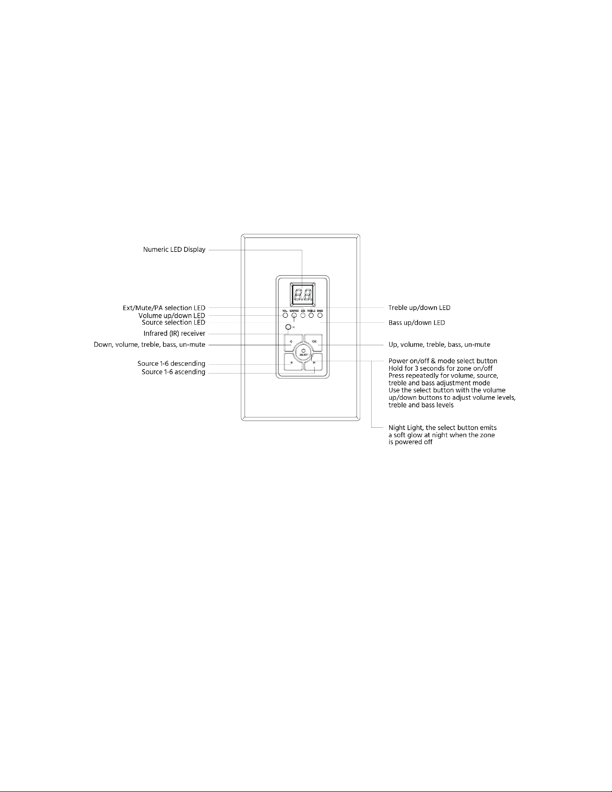
Keypad Controllers
24. LED Display: The digital LED display shows the number of the source device, as well
as the volume, treble, and bass levels.
25. Vol. LED: When illuminated, this LED indicates that the Numeric LED is displaying
the volume level. Use the Up and Down buttons to increase and decrease the
volume level.
26. Source LED: When illuminated, this LED indicates that the Numeric LED is displaying
the source selection.
27. Ext. LED: When illuminated, this LED indicates that the Mute function is enabled or
that a PA broadcast is in progress.

11
28. Treble Mode LED: When illuminated, this LED indicates that the Numeric LED is
displaying the treble level. Use the Up and Down buttons to increase and decrease
the treble level.
29. Bass Mode LED: When illuminated, this LED indicates that the Numeric LED is
displaying the bass level. Use the Up and Down buttons to increase and decrease
the bass level.
30. Infrared (IR) Receiver: The IR "eye" receives the infrared remote control signals.
Signals sent from the included remote control are used to control the wallplate
keypad, while signals from other remote controls are sent back to the Master
Controller, which distributes the signals to the source device via an external IR
emitter (not included).
31. Up Button: Use this button to increase the volume, treble, or bass levels, depending
on which mode is selected. If the zone is muted, pressing this button will unmute it.
32. Down Button: Use this button to decrease the volume, treble, or bass levels,
depending on which mode is selected. If the zone is muted, pressing this button will
unmute it.
33. Previous Source Button: Use this button to cycle backwards through the list of
available sources. For example, if source 4 is currently selected, pressing this button
will change to source 3.
34. Next Source Button: Use this button to cycle forward through the list of available
sources. For example, if source 4 is currently selected, pressing this button will
change to source 1.
35. Select/Power Button: Press and hold this button for about 3 seconds to turn the
zone on or off. When the zone is on, pressing the button will cycle through the
available adjustment modes.

12
IR Remote Control
36. IR Emitter: When using the remote control, the IR emitter should be pointed at the
IR receiver on the Keypad Controller.
37. Mute Button: Press this button to mute/unmute the zone.
38. Power Button: Press this button power the zone on or off.
39. Source Buttons: Press the +button to cycle forwards through the available source
devices and press the -button to cycle backwards through the available source
devices.
40. Treble Buttons: Press the +button to increase the treble level and press the -
button to decrease the treble level.

13
41. Bass Button: Press the +button to increase the bass level and press the -button to
decrease the bass level.
42. Volume Buttons: Press the +button to increase the volume level and press the -
button to decrease the volume level.
43. Balance Left Button: Press this button to move the stereo balance to the left.
44. Balance Right Button: Press this button to move the stereo balance to the right.
LOCATION PLANNING
Prior to installation you should make a detailed plan of exactly where you will install each
component and how you will route the necessary Ethernet cables to connect everything
together.
Determine where you will mount the Wallplate Keypad Controllers. Note that installation
of the keypads requires the use of a single-gang, low-voltage mounting bracket (not
included).
The Master Controller/Amplifier can be installed into a standard 19" equipment rack, using
the attached rack mount ears, or can be set on a shelf. Ensure that there is sufficient room
around all sides and that there is good airflow for cooling. Do not place other equipment
on top of the controller and do not install it in an enclosed space, such as a cabinet or
closet.
Of course, you will also need speakers for each zone. The built-in amplifiers in this unit are
capable of producing 60 watts per channel into 8 ohm speakers or 70 watts per channel
into 4 ohm speakers. Each amplifier can be individually bridged to produce 140 watts into a
single 8 ohm speaker. Do not attempt to use 4 ohm speakers with bridged mode.
Note: Even the best speaker cable has some resistance, which increases with the length of
the cable. The resistance of the cable must be added to the impedance of the speaker
when considering the total load presented to the amplifier. We recommend the use of 8
ohm speakers for longer cable runs, because the resistance added by the cable would
represent a smaller percentage of the total impedance and therefore would have a lesser
impact on sound quality.
14
CABLE PREPARATION
You will need a variety of cables for this installation, the specifics of which vary depending
on your installation choices. None of the cables or connectors mentioned in this section are
included with the system.
Important Safety Note! If you plan on running any of these cables through the walls,
through a connecting floor, or inside an air duct in commercial applications, they should be
rated for In-Wall, Riser (between floors), or Plenum (air duct) use, respectively. For
residential installations, an In-Wall rating is sufficient for all situations. Using unrated or
improperly rated cables could accelerate the spread of any fire and could nullify insurance
claims.
Ethernet Cables
The Wallplate Keypad Controllers connect to the Master Controller/Amplifier using Cat5e
or Cat6 Ethernet cables. The cables carry the low-voltage power needed for the keypad
operation and illumination, as well as the specific signals used to control the system.
Depending on the distance of each keypad from the Master Controller, you may be able to
use pre-made Ethernet cables. However, it is most likely that you will need to make custom
cables of the appropriate length for each zone. Additionally, Ethernet cable is used to
connect Inputs 5 and 6 on the Master Controller/Amplifier to digital audio source devices,
such as the model 13358 Multizone Source Keypad.
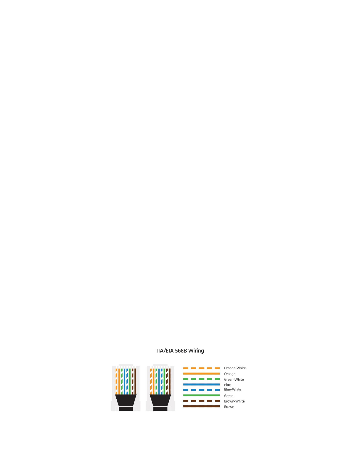
Each Ethernet cable should be wired to the TIA/EIA-568B standard, which is the standard
by which almost all currently available, pre-made Ethernet cables are constructed. The
following diagram shows the proper wiring for 568B connections:

15
It is a good idea to use a dedicated RJ45 cable tester to verify the proper operation of each
Ethernet cable prior to installation, especially if you are building the cables yourself and
especially if the cables will be routed through the walls, even if using pre-made cables. A
cable tester can save a lot of time and frustration in troubleshooting any connectivity
issues discovered during installation.
Speaker Wires
You will need speaker wire to connect each speaker in each zone to the Master
Controller/Amplifier. The size (AWG) of wire you choose depends on the distance from the
amplifier to the speaker(s), the speaker impedance, and the physical limits of the terminals
at each end.
Other than saving a few pennies of cost or grams of weight per foot, there is no reason to
use anything other than the thickest wire possible. The Master Controller/Amplifier uses
Euroblock Terminal connectors, which can accept up to 14 AWG wire, so it is recommended
to use 14 AWG speaker wire. If the speaker terminals cannot accept 14 AWG wire, you can
use a banana or pin plug to connect the wire to the speaker terminal.
Whatever speaker wire you get, make sure that it has marks to identify one conductor
from another. Most speaker wire uses a colored stripe to identify one of the conductors.
The identified conductor is usually used for the positive (+/red) connection and the other
for the negative (-/black) side.
Note: When cutting speaker wire, ensure that the length of each stereo pair is the same.
This ensures that the overall impedance of each channel is identical. If there is any excess
speaker wire, it should not be coiled, as it could create an antenna to receive stray radio
signals. Instead, snake the excess wire back and forth.
RCA Cables
If there is a significant distance from the Master Controller/Amplifier to a given speaker
zone, it might be better to use an external power amplifier to power the speakers in that
zone. If this is the case, you will need stereo RCA cables to connect from the preamp
outputs to the inputs of the external amp.

16
While long line-level or preamplifier level RCA cables are less susceptible to interference
over long distances, it is recommended to use RCA cables manufactured using shielded
RG6 or RG59 cable.
In addition to the preamp connections, you will need a stereo RCA cable to connect up to
two source devices to the Master Controller/Amplifier's source inputs. In most cases these
will be relatively short connections, so it is not necessary to use RG-based cables.
3.5mm TRS Cables
Inputs 3 and 4 can accept analog stereo audio signals from a three-conductor 3.5mm TRS
audio cable. You can use premade 3.5mm audio cables or can make them yourself using
three conductor cable and 3.5mm TRS plugs.
Mini Toslink® Cable
In addition to analog stereo audio signals, Input 4 can also accept digital optical audio
(S/PDIF) signals from a fiber optical Mini Toslink cable. Premade Mini Toslink cables are
available in a variety of lengths.
Trigger Cables
This system includes several trigger inputs and outputs. The trigger outputs can be
connected to the trigger inputs of responsive devices, such as projection screens, lighting
systems, curtain motors, etc. The trigger inputs allow the Master Controller to respond to
external trigger events, such as a PA or mute signal.
The trigger signal consists of a low-current 12 VDC signal applied to the input, which is
carried between systems with a two-conductor cable that terminates in a 3.5mm TS plug.
You can user premade TS cables or can make them yourself using 2-conductor wire and
3.5mm TS plugs.
Note that you can also use 3-conductor 3.5mm TRS cables instead of TS cables.

17
RS232 Serial Cable
If you will be using the RS232 external control option, you will need to have an RS232 serial
cable to connect your PC to the Master Controller/Amplifier. The specific wiring needs of
this cable are determined by your specific setup. You will need a male DB9 (DE9) plug on
the end that connects to the Master Controller/Amplifier.
See the
RS232 Serial Control
section for more information about the control codes used by
the system.
IR Emitters
This system has the ability to repeat IR signals from each speaker zone to control the
source devices. To carry the IR signal from the Master Controller/Amplifier to the actual
source device requires the use of IR emitters (not included). The IR emitters connect to the
Master Controller via a 3.5mm TS plug. If the emitters are not long enough, you can use
standard 3.5mm TS or TRS extension cables to increase their lengths.
The IR repeater function supports single-band IR signals only (those in the 38KHz range).

18
INSTALLATION
Note: Before making any connections, ensure that all equipment is powered off and
unplugged to prevent the possibility of personal injury or equipment damage due to
electrical shock.
Test Installation
Before drilling any holes and before running any cables through walls, it is highly
recommended to perform a test installation first. The test installation should consist of a
complete connection of all speakers, wallplates, source devices, etc., so that full
functionality can be verified prior to making permanent or difficult installation actions.
Ideally, you should route cables from the master location to the intended location of each
zone, connect speakers and wallplate keypads in each zone, and perform full functionality
testing using the keypads, the system's remote control, and any remote controls for
connected source devices.
Connecting Multiple Multizone Controllers
If you will be using multiple multizone controllers, you will need to connect them together
using the ribbon cable supplied with each unit.
1. Decide which device will be the Master device. Slide the Master/Slave switch on
this unit to the Master position.
2. Plug one end of the included ribbon cable into the Expansion Output port on the
back of the Master device. Plug the other end into the Expansion Input port on the
back of the first slave device.
3. Slide the Master/Slave switch on the first slave device to the Slave 1 position.
4. If connecting a third controller, plug one end of the included ribbon cable into the
Expansion Output port on the back of the first slave device. Plug the other end into
the Expansion Input port on the back of the second slave device.
5. Slide the Master/Slave switch on the second slave device to the Slave 2 position.

19
Connecting the Wallplate Keypad Controllers
1. Set the three DIP switches on each Keypad Controller to one of the four
identification patterns listed below. Each Keypad Controller connected to the same
Master Controller/Amplifier must have a unique identification. Note that the
identification is localized to each Master Controller/Amplifier device. If multiple
Master Controllers are in use, each one will have its own set of keypads with the
same identification numbers as keypads on another Master Controller.
2. Connect one end of an Ethernet cable to the RJ45 port on the front of the Keypad
In-Wall Hub Connection Plate. Connect the other end to the Keypads port on the
back of the Master Controller/Amplifier.
3. Repeat step 2 for each other Master Controller/Keypad In-Wall Hub Connection
Plate set in the system.
4. Connect one end of an Ethernet cable to the RJ45 port on the back of one of the
Keypad Controllers. Connect the other end to one of the RJ45 ports on the back of
the Keypad In-Wall Hub Connection Plate. It does not matter which port is
connected because the DIP switches are used to identify each Keypad Controller.
5. Repeat step 4 for each other Keypad Controller in the system.

20
Connecting External Amplifiers
If you are using an external amplifier for one or more zones, perform steps 1-4 below for
each external amplifier in the system.
1. Plug one end of a stereo RCA cable into the input jacks on the back of the external
amplifier. Plug the other end into the appropriately numbered Preamp Output on
the back of the Master Controller/Amplifier.
2. Connect one end of a speaker wire to the positive and negative terminals on the
left channel speaker. Connect the other end to the positive and negative left
channel speaker out terminals on the external amplifier. Ensure that the polarity is
properly maintained at each end.
3. Connect the right channel speaker in the same way you connected the left channel
in step 2 above.
4. Visually inspect each connection to ensure that there are no stray strands of wire
sticking out of any of the connections. If there are, fix the connection before
proceeding.
Connecting the Speaker Wires
For each zone that will be powered using the built-in amplifiers in the Master Controller,
perform steps 1-6 below.
1. Pull on the Euroblock terminal block on the back of the Master Controller/Amplifier
to detach it from the device.
2. Strip about 1/4" of insulation from the ends of each conductor on the speaker wires
for this zone. Twist the wire tightly so that there are no stray strands.
3. Carefully insert the positive and negative conductors on each speaker wire into the
appropriate sockets in the Euroblock terminal. Tighten the screws on the terminal
block until there is a good, solid mechanical and electrical connection.
4. Connect the other ends of each speaker wire to the positive and negative terminals
on each of the two speakers. Pay close attention to the polarity to ensure that it is
maintained at each end.
Table of contents


