TEXIO LW Series User manual

© PRINTED IN JAPAN B71-0006-00
INSTRUCTION MANUAL
MULTI-INPUT ELECTONIC LOADING UNITS
LW SERIES
LW75-151Q LW151-151D
LW75-151D LW301-151S
EXTERNAL INTERFACE UNITS
IF-50GP IF-50USB

2

SAFETY
●Symbol in This Manual
This symbol indicates where applicable cautionary or other information is to be found.
●Power Source
This equipment operates from a power source that does not apply more than 250V rms between the
supply conductors or between both supply conductor and ground. A protective ground connection by
way of the grounding conductor in the power cord is essential for safe operation.
●Grounding the Product
This equipment is grounded through the grounding conductor of the power cord. To avoid electrical
shock, plug the power cord into a properly wired receptacle before connecting to the equipment input
or output terminals.
●Use the Proper Power Cord
Use only the power cord and connector specified for your product.
●Use the Proper Fuse
To avoid fire hazard, use a fuse of the correct type.
●Do not Operate in Explosive Atmospheres
To avoid explosion, do not operate this product in an explosive atmosphere.
●Do not Remove Cover or Panel
To avoid personal injury, do not remove the cover or panel. Refer servicing to qualified personnel.
●If the equipment is used in a manner not specified, the protection provided by the equipment may be
impaired.

TABLE OF CONTENTS
SAFETY
1. ABOUT THIS PRODUCT....................................................................................................................... 1
1-1 About This Manual............................................................................................................................ 1
1-2 Product Overview ............................................................................................................................. 1
1-3 Features............................................................................................................................................ 1
1-3-1 LW electronic loading unit.......................................................................................................... 1
1-3-2 IF-50GP (Option) ....................................................................................................................... 2
1-3-3 IF-50USB (Option)..................................................................................................................... 2
2. SPECIFICATIONS.................................................................................................................................. 3
2-1 aximum Input Rating......................................................................................................................... 3
2-2 Constant-Current Mode.................................................................................................................... 3
2-3 Constant-Resistance Mode .............................................................................................................. 4
2-4 Constant-Voltage Mode.................................................................................................................... 4
2-5 Constant-Power Mode...................................................................................................................... 5
2-6 Current Limitation ............................................................................................................................. 5
2-7 Switching Mode ................................................................................................................................ 6
2-8 DC Current Measurement ................................................................................................................ 6
2-9 DC Voltage Measurement ................................................................................................................ 6
2-10 DC Power Measurement................................................................................................................ 6
2-11 Voltage Remote Sensing ................................................................................................................ 7
2-12 External Contact Control ................................................................................................................ 7
2-13 External Voltage Control................................................................................................................. 7
2-14 Protection Functions....................................................................................................................... 7
2-15 Use Conditions, Size, etc. .............................................................................................................. 8
2-16 External Interface Control............................................................................................................... 8
2-17 Communication Specifications of IF-50GP .................................................................................... 8
2-18 Communication Specifications of IF-50USB .................................................................................. 8
3. PRECAUTIONS ..................................................................................................................................... 9
3-1 Checking Source Voltage ................................................................................................................. 9
3-2 Connecting Power Cable.................................................................................................................. 9
3-3 Instruction on Connecting Input Terminals....................................................................................... 9
3-4 Installation Environment................................................................................................................. 10
3-5 Current Limit Setting....................................................................................................................... 10

4. PANELS ................................................................................................................................................11
4-1 Front Panel ......................................................................................................................................11
4-2 Rear Panel...................................................................................................................................... 15
4-3 Optional Board Mount .................................................................................................................... 17
5. BEFORE USING UNIT......................................................................................................................... 18
5-1 Position of Voltage Remote Sensing Selector Switches................................................................ 18
5-2 Connection of Power Supply.......................................................................................................... 19
5-2-1 Connecting with input terminals on front panel ....................................................................... 19
5-2-2 Connecting with input terminals on rear panel........................................................................ 20
5-3 Turning On Power........................................................................................................................... 21
5-3-1 Display when turning on power ............................................................................................... 21
5-3-2 Setting when turning on power and storing setting ................................................................. 22
5-4 Alarm............................................................................................................................................... 23
5-4-1 EAR (External alarm)............................................................................................................... 23
5-4-2 OHA (Overheat alarm) .............................................................................................................. 23
5-4-3 OVA (Over-voltage application alarm) ....................................................................................... 23
5-4-4 OCA (Over-current input alarm) .............................................................................................. 23
5-5 Limit Functions ............................................................................................................................... 24
5-5-1 Over-power limit (OPL)............................................................................................................ 24
5-5-2 Current limit (CL) ..................................................................................................................... 24
5-6 Replacement of Power Fuse.......................................................................................................... 24
6. FUNCTIONS AND OPERATION PROCEDURES............................................................................... 25
6-1 Operation Method Selecting Function............................................................................................ 25
6-1-1 Selecting operation method..................................................................................................... 25
6-1-2 Switching method selection..................................................................................................... 26
6-1-3 Time-out time selection............................................................................................................ 26
6-1-4 Rear contact function selection ............................................................................................... 27
6-2 Function Setting Mode ................................................................................................................... 28
6-2-1 Function setting mode operation............................................................................................. 28
6-2-2 Delay time setting .................................................................................................................... 29
6-2-3 Tracking operation setting ....................................................................................................... 30
6-2-4 Discharge mode setting........................................................................................................... 31
6-2-5 Switching time setting method 1.............................................................................................. 32
6-2-6 Switching time setting method 2.............................................................................................. 33
6-2-7 Changing input voltage display and input power display ........................................................ 34
6-2-8 Changing input value display and set value display ............................................................... 34
6-2-9 Display of two input current values: The LW301-151S does not have this function............... 35
6-2-10 Increasing and decreasing set values of CC, CV and CP modes ........................................ 35

6-2-11 Increasing and decreasing set values of CR mode............................................................... 37
6-2-12 Setting CR mode value by means of voltage and current setting......................................... 39
6-2-13 Increasing and decreasing current limit set value................................................................. 40
6-3 Memory Functions ...................................................................................................................... 41
6-3-1 Storing preset values (discharge mode and set value) in EEPROM ...................................... 41
6-3-2 Storing key settings in EEPROM............................................................................................. 41
6-3-3 Recalling preset data with PRESET keys ............................................................................... 42
6-3-4 Checking preset data and increasing/decreasing set value when MAIN INPUT key is lit...... 42
6-3-5 Initializing set value ................................................................................................................. 43
6-4 Input Functions ............................................................................................................................... 44
6-4-1 Turning on input....................................................................................................................... 44
6-4-2 Turning off input....................................................................................................................... 44
6-5 Switching Functions........................................................................................................................ 45
6-5-1 Turning on/off switching........................................................................................................... 45
6-6 Delay Functions.............................................................................................................................. 46
6-6-1 Turning on input using delay function...................................................................................... 46
6-6-2 Turning off input using delay function...................................................................................... 46
6-7 Tracking Functions ......................................................................................................................... 47
6-7-1 Turning on/off tracking operation............................................................................................. 47
6-7-2 Increasing or decreasing set value in absolute value tracking mode ..................................... 48
6-7-3 Checking CR mode set resistance in absolute value tracking mode...................................... 48
6-7-4 Increasing or decreasing set value in % tracking mode ......................................................... 49
6-7-5 Checking set value in % tracking mode .................................................................................. 50
6-7-6 Example of increasing/decreasing set values with tracking mode active............................... 51
6-8 Releasing Alarms............................................................................................................................ 51
6-8-1 Occurrence of EAR (external alarm) and releasing it ............................................................. 51
6-8-2 Occurrence of OHA (overheat alarm) and releasing it............................................................ 52
6-8-3 Occurrence of OVA (over-voltage application alarm) and releasing it .................................... 52
6-8-4 Occurrence of OCA (over-current input alarm) and releasing it.............................................. 52
6-9 Key Lock Function.......................................................................................................................... 53
6-10 Usage of Voltage Remote Sensing Function ............................................................................... 53
7. EXTERNAL CONTACT CONTROL..................................................................................................... 54
7-1 Functions ........................................................................................................................................ 54
7-2 Specifications of Remote Contact Control Connector.................................................................... 54
7-3 Usage ............................................................................................................................................. 55
7-3-1 External alarm terminals....................................................................................................... 55
7-3-2 Selecting PRESET 1 to 4 keys using external contacts.......................................................... 55
7-3-3 Turning ON/OFF input select using external contacts ............................................................ 56
7-3-4 Turning ON/OFF main input using external contacts .............................................................. 56

8. EXTERNAL VOLTAGE CONTROL ..................................................................................................... 57
8-1 Pins for External Voltage Control ................................................................................................... 57
8-1-1 Specifications of J2.................................................................................................................. 57
8-1-2 Connecting external voltage source and J2 ............................................................................ 57
8-1-3 Specifications of controls......................................................................................................... 58
8-2 Usage of External Voltage Control Function .................................................................................. 58
8-2-1 Checking set value of external voltage control........................................................................ 58
8-2-2 Adjusting set value using external voltage .............................................................................. 59
8-2-3 Operation in CC mode............................................................................................................. 60
8-2-4 Relationship between external voltage and set value in CC mode ........................................ 61
8-2-5 Operation in CR/CV/CP mode................................................................................................. 62
8-2-6 Relationship between external voltage and set value in CR/CV/CP mode ............................ 62
9. REMOTE CONTROL ........................................................................................................................... 63
9-1 Connection of IF-50GP or 1F-50USB ............................................................................................ 63
9-1-1 Control through GP-IB............................................................................................................. 63
9-1-2 Control through USB ............................................................................................................... 63
9-1-3 Connection Figure of IF-50GP/USB........................................................................................ 64
9-1-4 Connection of IF-50GP/1F-50USB local bus .......................................................................... 65
9-2 Address Setting .............................................................................................................................. 65
9-2-1 Addresses ................................................................................................................................ 65
9-2-2 Address setting ........................................................................................................................ 66
9-2-3 Address setting range and set value ....................................................................................... 66
9-3 Precautions for Using GP-IB or USB ............................................................................................. 66
9-3-1 Using GP-IB............................................................................................................................. 66
9-3-2 Using USB ............................................................................................................................... 66
9-4 Precautions for Sending Commands ............................................................................................. 67
9-4-1 Sending commands................................................................................................................. 67
9-4-2 Command format..................................................................................................................... 67
10. COMMANDS...................................................................................................................................... 68
10-1 Setting Commands....................................................................................................................... 68
10-1-1 Setting units to be controlled ................................................................................................. 68
10-1-2 PRESET key selection .......................................................................................................... 68
10-1-3 Discharge mode setting......................................................................................................... 68
10-1-4 Main input ON/OFF ............................................................................................................... 69
10-1-5 Input select ON/OFF.............................................................................................................. 69
10-1-6 Setting discharge mode set value ......................................................................................... 70
10-1-7 Setting STEP value of CR mode........................................................................................... 70
10-1-8 Setting current limit value...................................................................................................... 71

10-1-9 Saving preset data in EEPROM ............................................................................................ 71
10-1-10 Turning on or off switching select function .......................................................................... 71
10-1-11 Setting switching frequency................................................................................................. 72
10-1-12 Setting switching duty.......................................................................................................... 72
10-1-13 Setting switching time.......................................................................................................... 72
10-1-14 Changing switching method ................................................................................................ 73
10-1-15 Turning on/off delay operation............................................................................................. 73
10-1-16 Setting delay time................................................................................................................ 73
10-1-17 Saving set values in EEPROM............................................................................................ 73
10-1-18 Saving discharge mode set value in EEPROM................................................................... 74
10-1-19 Saving current limit value in EEPROM................................................................................ 74
10-1-20 Setting time-out time............................................................................................................ 74
10-1-21 Resetting alarms.................................................................................................................. 74
10-1-22 Selecting input value display channel ................................................................................. 75
10-1-23 Selecting input value to be displayed.................................................................................. 75
10-1-24 Local setting (Canceling key locking) ............................................................................... 75
10-1-25 Setting lockout status .......................................................................................................... 75
10-1-26 Tracking setting ................................................................................................................... 76
10-1-27 Setting tracking mode.......................................................................................................... 76
10-1-28 Turning On/Off tracking operation ....................................................................................... 76
10-1-29 Increasing/decreasing set value in tracking operation........................................................ 77
10-2 Query Commands ........................................................................................................................ 78
10-2-1 Sending system addresses of controlled units...................................................................... 78
10-2-2 Sending addresses of all slave units..................................................................................... 78
10-2-3 Sending option board ID and model ID of unit ...................................................................... 78
10-2-4 Query about input value ........................................................................................................ 79
10-2-5 Query about selected PRESET key ...................................................................................... 79
10-2-6 Query about discharge mode................................................................................................ 79
10-2-7 Query about main input On/Off status................................................................................... 80
10-2-8 Query about input select status............................................................................................. 81
10-2-9 Inquiry about set values ........................................................................................................ 81
10-2-10 Query about STEP value in CR mode ................................................................................ 81
10-2-11 Query about set current limit ............................................................................................... 82
10-2-12 Query about switching select status.................................................................................... 82
10-2-13 Query about switching frequency........................................................................................ 83
10-2-14 Query about switching duty................................................................................................. 83
10-2-15 Query about set switching time ........................................................................................... 83
10-2-16 Query about switching method............................................................................................ 84
10-2-17 Query about delay function On/Off status ........................................................................... 84
10-2-18 Query about set delay time ................................................................................................. 84

10-2-19 Query about unit ID number................................................................................................ 85
10-2-20 Query about set time-out time............................................................................................. 85
10-2-21 Query about alarm status .................................................................................................... 86
10-2-22 Query about limit operation status....................................................................................... 86
10-2-23 Query about input value display channel ............................................................................ 87
10-2-24 Query about displayed input value...................................................................................... 87
10-2-25 Query about local lockout status ......................................................................................... 87
10-2-26 Query about tracking setting ............................................................................................... 88
10-2-27 Query about tracking mode................................................................................................. 88
10-2-28 Query about tracking operation On/Off status..................................................................... 88
10-2-29 Query about % tracking mode set value ............................................................................. 89
10-3 Command List .............................................................................................................................. 90
10-3-1 Setting commands................................................................................................................. 90
10-3-2 Query commands .................................................................................................................. 91
11. TROUBLE-LOOKING PHENOMENA ............................................................................................... 92
12. OUTSIDE DIMENSIONS ................................................................................................................... 93

1
1. ABOUT THIS PRODUCT
1-1 About This Manual
Applicable models: LW series electronic loading units
LW75-151Q, LW75-151D, LW151-151D and LW301-151S
Optional interface units for the LW series electronic loading units
IF-50GP: Interface for GP-IB communication
IF-50USB: Interface for USB communication
1-2 Product Overview
The LW series is a multi-input type electronic loading unit with several isolated input terminals. The
basic function of the LW series is the CC discharge mode using the input terminals on the rear panel.
Three discharge modes (CR, CV and CP), front input terminals, voltage remote sensing functions,
and control functions according to external analog voltages are also available as optional functions
on request. In addition, the LW series provides tracking, delay and four-point preset functions for a
wide variety of applications.
1-3 Features
1-3-1 LW electronic loading unit
・Tracking function (exclusive of LW301-151S)
The LW series employs a tracking function, which may vary the voltage and current of each
channel at the same ratio (or absolute value) simultaneously. It is possible to use the tracking
function independently in each channel or vary all channels simultaneously.
・Delay function (exclusive of LW301-151S)
The LW series has a delay function, which delays turning on or off the input of a specified
channel by specified time when turning on several channels. It is possible to set the delay time
of each channel independently in the range from 0.01 to 10.00 seconds.
・Preset function
The LW series has four-point preset memories, each of which may store the discharge mode
and set values of a channel. This function enables easy changing of the set values.
・Input value display function
The LW series displays the voltage, current and power on four-digit, seven-segment red LEDs.
・Individual input ON/OFF setting function
It is possible to turn on or off the input of each channel individually. The input ON/OFF
condition of each channel is indicated with an LED clearly.
・Individual switching ON/OFF setting function
It is possible to turn on or off the input of each channel individually. The switching ON/OFF
condition of each channel is indicated with an LED clearly.

2
・Switching time setting method selecting function
It is possible to select the switching time setting; "frequency and duty" or "Ta time and Tb time".
・External contact control function
It is possible to select the PRESET 1 to 4 keys, turn on or off the individual input (except the
LW301-151S), turn on or off the main input, and input or output alarms through the external
contacts.
・Voltage remote sensing function (Factory option)
Each channel has voltage remote sensing terminals. This function enables voltage
measurement of the power supply by compensating for the voltage drop of the wires.
・Slide terminal structure (Factory option)
The input terminals on the front panel have a sliding structure. This structure fixes wires to the
terminals firmly and securely.
1-3-2 IF-50GP (Option)
・Connect the LW series with a computer through the GP-IB. GP-IB connection allows fourteen
LW electronic loading units to be connected with a computer directly.
・It is also possible to connect thirty-one LW units with each LW unit directly connected with the
computer using a pair of twisted pair cables and remote-control them. Thus, the IF-50GP unit
enables construction of a large-scale system.
NOTE: This option is not available to an LW series with the external analog voltage control
functions added by factory option.
1-3-3 IF-50USB (Option)
・Connect the LW series with a computer through USB. USB connection allows thirty-two LW
electronic loading units to be connected with a computer directly.
・It is also possible to connect thirty-one LW units with each LW unit directly connected with the
computer using a pair of twisted pair cables and remote-control them. Thus, the IF-50USB unit
enables construction of a large-scale system.
NOTE: This option is not available to an LW series with the external analog voltage control
functions added by factory option.

3
2. SPECIFICATIONS
2-1 aximum Input Rating
Item Model
LW75-151Q
LW75-151D H current range: 75 W, L current range: 12.5 W
LW151-151D H current range: 150 W, L current range: 25 W
Input voltage
LW301-151S H current range: 300 W, L current range: 50 W
LW75-151Q
LW75-151D H current range: 15 A, L current range: 2.5 A
LW151-151D H current range: 30 A, L current range: 5 A
LW301-151S H current range: 60 A, L current range: 10 A
Input current
LW301-151S
front
input type
H current range: 30 A, L current range: 10 A
Application voltage All models 150 V
LW75-151Q 4 (Std.: rear, factory option: front)
LW75-151D
LW151-151D 2 (Std.: rear, factory option: front)
Input terminals
LW301-151S 1 (Std.: rear, factory option: front)
2-2 Constant-Current Mode
Item Model
Input vol. range All models Rear: 1 to 150 V
front: 1.5 to 150 V
LW75-151Q
LW75-151D
H current range: 0.000 to 15.750 A (0 to 105% FS)
L current range: 0.0000 to 2.6250 A (0 to 105% FS)
LW151-151D H current range: 0.000 to 31.500 A (0 to 105% FS)
L current range: 0.0000 to 5.3000 A (0 to 105% FS)
LW301-151S H current range: 0.000 to 63.000 A (0 to 105% FS)
L current range: 0.0000 to 10.500 A (0 to 105% FS)
Setting range
LW301-151S
front input
type
H current range: 0.000 to 31.500 A (0 to 105% FS)
L current range: 0.0000 to 10.500 A (0 to 105% FS)
LW75-151Q
LW75-151D
H current range: 1 mA
L current range: 0.1 mA
LW151-151D H current range: 2 mA
L current range: 0.2 mA
Theoretical resolution
LW301-151S H current range: 5 mA
L current range: 1 mA
Setting accuracy All models ±(0.5% SET + 0.3% FS) at 23 ±5℃ 1% FS current or more
LW75-151Q
LW75-151D
H current range: 5 mA
(Actual value measured in 5 to 1MHz range)
L current range: 3 mA
(Actual value measured in 5 to 1MHz range)
LW151-151D
H current range: 10 mA
(Actual value measured in 5 to 1MHz range)
L current range: 6 mA
(Actual value measured in 5 to 1MHz range)
Ripple noise
LW301-151S
H current range: 20 mA
(Actual value measured in 5 to 1MHz range)
L current range: 10 mA
(Actual value measured in 5 to 1MHz range)
Temperature
coefficient All models 100ppm/℃: time of rated current
・The constant-current circuit of the LW series has an internal reference power source for each
preset. Thus, when the same current is set for all presets, the control current may differ with
the presets.

4
2-3 Constant-Resistance Mode
Item Model
Input vol. range All models Rear: 0 to 150 V, front: 0 to 150 V
LW75-151Q
LW75-151D
H current range: 1 k to 0.1 Ω
L current range: 6 k to 0.6 Ω
LW151-151D H current range: 500 to 0.05 Ω
L current range: 3 k to 0.3 Ω
Setting range
Resistances shown
on right correspond
to STEP values of 3
to 30000. LW301-151S H current range: 250 to 0.025 Ω
L current range: 1.5 k to 0.15 Ω
LW75-151Q
LW75-151D
H current range: 333
.
μS (= 1/3 k Ω)
L current range: 55.5
.
μS (= 1/18 k Ω)
LW151-151D H current range: 666
.
μS (= 1/1.5 k Ω)
L current range: 111
.
μS (= 1/9 k Ω)
Theoretical resolution
LW301-151S H current range: 1.33
.
mS (= 1/750 Ω)
L current range: 222 μS (= 1/4.5 k Ω)
Setting accuracy All models
±(2% Vin/Rset + 1.5% FS current)
Vin = 1.5 or more, at 23 ±5℃, set current: 10% FS current or
more
LW75-151Q
LW75-151D
H current range: 5 mA
(Actual value measured in 5 to 1MHz range)
L current range: 3 mA
(Actual value measured in 5 to 1MHz range)
LW151-151D
H current range: 10 mA
(Actual value measured in 5 to 1MHz range)
L current range: 6 mA
(Actual value measured in 5 to 1MHz range)
Ripple noise
LW301-151S
H current range: 20 mA
(Actual value measured in 5 to 1MHz range)
L current range: 10 mA
(Actual value measured in 5 to 1MHz range)
Temperature
coefficient All models 1000ppm/℃: time of rated electric power and time of rated
current
・The resistances shown above are calculated using the following expression:Resistance =
1/(theoretical resolution × STEP)
・The constant-resistance circuit of the LW series has an internal reference power source for each
preset. Thus, when the same resistance is set for all presets, the control resistance may differ
with the presets.
・The constant-resistance circuit of the LW series switches three circuits to execute resistance
control according to the set steps. Thus, the set resistance may change greatly in the setting
accuracy range when the circuit is switched (at two points between the set steps 300 and 301
and steps 3000 and 3001).
2-4 Constant-Voltage Mode
Item Model
Setting range All models 0.00 to 157.50 V (0 to 105% FS)
Min. operating
current All models 1% FS current
Theoretical resolution
All models 10 mV
Setting accuracy All models ±(0.5% SET + 0.3% FS) at 23 ±5℃
Application voltage -- Front: 1.5 V or more, rear: 1 V or more
CV temperature
coefficient All models 150 ppm/℃: time of rated voltage
・The constant-voltage circuit of the LW series has an internal reference power source for each
preset. Thus, when the same voltage is set for all presets, the control voltage may differ with
the presets.

5
2-5 Constant-Power Mode
Item Model
Input
vol. range All models H voltage range: 5 to 150 V
L voltage range: 1 to 15 V
LW75-151Q
LW75-151D
H current range: 3.75 to 78.75 W (5 to 105% FS)
L current range: 0.625 to 13.12 W (5 to 105% FS)
LW151-151D H current range: 7.50 to 157.50 W (5 to 105% FS)
L current range: 1.25 to 26.25 W (5 to 105% FS)
Setting range
LW301-151S H current range: 15.00 to 315.00 W (5 to 105% FS)
L current range: 2.500 to 52.500 W (5 to 105% FS)
LW75-151Q
LW75-151D
H current range: 10 mW
L current range: 1 mW
LW151-151D H current range: 20 mW
L current range: 2 mW
Theoretical
resolution
LW301-151S H current range: 50 mW
L current range: 5 mW
Setting
accuracy All models ±(5% SET + 2% FS) at 23 ±5°C , at constant current over 5%
LW75-151Q
LW75-151D
H current range: 8 mA
(Actual value measured in 5 to 1MHz range)
L current range: 5 mA
(Actual value measured in 5 to 1MHz range)
LW151-151D
H current range: 16 mA
(Actual value measured in 5 to 1MHz range)
L current range: 10 mA
(Actual value measured in 5 to 1MHz range)
Ripple noise
LW301-151S
H current range: 32 mA
(Actual value measured in 5 to 1MHz range)
L current range: 20 mA
(Actual value measured in 5 to 1MHz range)
Temperature
coefficient All models 1000ppm/°C: time of rated electric power and time of rated current
The constant-power circuit of the LW series has an internal reference power source for each preset.
Thus, when the same power is set for all presets, the control power may differ with the presets.
2-6 Current Limitation
Item Model
LW75-151Q
LW75-151D
H current range: 0.75 to 15.75 A (5 to 105% FS)
L current range:0.125 to 2.625 A (5 to 105% FS)
LW151-151D H current range: 1.50 to 31.50 A (5 to 105% FS)
L current range:0.250 to 5.250 A (5 to 105% FS)
LW301-151S H current range: 3.00 to 63.00 A (5 to 105% FS)
L current range:0.50 to 10.50 A (5 to 105% FS)
Setting range
LW301-151S
front input
type
H current range: 3.00 to 31.500 A (10 to 105% FS)
L current range:0.50 to 10.500 A (5 to 105% FS)
LW75-151Q
LW75-151D
H current range: 10 mA
L current range:1m A
LW151-151D H current range: 20 mA
L current range:2m A
Theoretical
resolution
LW301-151S H current range: 50 mA
L current range:10m A
Setting
accuracy All models ±(1% SET + 1.5% FS) at 23 ±5°C

6
2-7 Switching Mode
Item
Operation mode Preset value 1/2 or 3/4 switching
Setting method 1: Frequency and duty
Frequency setting range 1 to 500 Hz
Frequency setting accuracy ±5% SET
Frequency setting resolution 1 Hz
Duty setting range 5 to 95%
Duty setting accuracy 3% SET
Duty setting resolution 1%
Setting method 2: Ta time and Tb time
Time setting range Ta & Tb time: 0.1 to 900.0 ms
Time setting accuracy ±5% SET
Time setting resolution 0.1 ms
・Setting method 1 and setting method 2 may not be used simultaneously. Select either method when
turning on power.
・The time setting range of method 2 is 0.1 to 900.0 ms. However, time exceeding the preset
frequency and duty range of method 1 may not be set.
Frequency setting range = 1/(Ta time + Tb time) within 1 to 500 Hz
Duty setting range = {Ta time/(Ta time + Tb time)} × 100 within 5% to 95%
2-8 DC Current Measurement
Item Model
LW75-151Q
LW75-151D
LW151-151D
H current range: 10 mA
L current range: 1 mA Resolution
LW301-151S 10m A
Accuracy All models ±(0.5%RDG+0.3%FS) at 23℃±5℃
Measurement
frequency All models Twice or more/sec.
2-9 DC Voltage Measurement
Item
Resolution 100 mV/10 mV (Automatic range. Hysteresis: 90/100 V)
Accuracy ±(0.5%RDG+0.3%FS) at 23℃±5℃
Measurement
frequency Twice or more/sec.
2-10 DC Power Measurement
Item Model
LW75-151Q
LW75-151D
LW151-151D
H current range: 100 mw
L current range: 10 mw Resolution
LW301-151S 100m W
Accuracy All models ±(1%RDG+0.6%FS) at 23℃±5℃, at constant current over
10%
Measurement
frequency All models Twice or more/sec

7
2-11 Voltage Remote Sensing
Item
Correction voltage 1 V, one way (Load input terminal voltage is between min. operating voltage
and 150 V.)
2-12 External Contact Control
Item
Main input ON/OFF Main input is turned on by short-circuiting the contacts.
PRESET 1 to 4 selection PRESET 1 to 4 is selected by short-circuiting the contacts.
Input select ON/OFF Input select of each channel is turned on by short-circuiting the
contacts.
Alarm IN/OUT
IN: Main input is turned off by short-circuiting the contacts.
OUT: Contacts are short-circuited and main input is turned off when an
alarm (OVA, OCA or OHA) occurs.
2-13 External Voltage Control
Item
Input voltage Set value (0 to 100%) in each discharge mode is adjusted with setting
control knob according to external voltage between 0 and 10 V.
Set value updating time CC mode: Real time, other mode: 2 seconds
2-14 Protection Functions
Item
Out of input
voltage range
(OVA)
Occurrence condition: Input voltage over approx. 165 V
Operation: Input select of channel where OVA occurs is turned off .
Recovery condition: Canceling displayed alarm after eliminating occurrence
condition.
Over-current
(OCA)
Occurrence condition: 115% or more of rated input current
Operation: Input select of channel where OCA occurs is turned off .
Recovery condition: Canceling displayed alarm after eliminating occurrence
condition.
Over-power (OPL)
Occurrence condition: 115% or more of rated input current
Operation: Power limiting circuit of channel where OPL occurs works.
Recovery condition: Eliminating occurrence condition.
Overheat (OHA)
Occurrence condition: Internal heat sink temperature is approx. 120℃.
Operation: Main input is turned off .
Recovery condition: Canceling displayed alarm after eliminating occurrence
condition.
Reverse
connection Short circuiting with internal protection diode

8
2-15 Use Conditions, Size, etc.
Item
Use temperature 0 to 40℃
Use humidity 20 to 85% (No condensation)
Storage temperature -20 to 60℃
Storage humidity 20 to 85% (No condensation)
Source voltage AC 100 V / 120V / 200V / 220V ±10%
Source frequency 50/60 Hz
Power consumption Approx. 75 VA
Dielectric strength Primary - casing: 1500 VAC for 1 minute
Primary - secondary: 1500 VAC for 1 minute
Primary - casing, primary - secondary: 500 VDC, 10 MΩ
Insulation resistance Secondary - casing: 250 VDC, 5 MΩ
Cooling method Forced cooling with fan
Outside dimensions 138 W x 124 H x 380 D mm
Maximum dimensions 138 W x 148 H x 458 D mm
Weight Approx. 7.1 kg
Accessories
Rear ext. control connector: 1
Instruction manual: 1 (English)
Three-core power cable
Rear terminal cover
Screws & nuts for rear terminal connection
Adjusting screwdriver (only for models with control functions based on
external voltages)
2-16 External Interface Control
Item
GP-IB Possible to read back set values and input values with IF-50GP.
USB Possible to read back set values and input values with IF-50USB.
2-17 Communication Specifications of IF-50GP
Electrical specifications Conforms to IEEE488-1978.
Mechanical specifications
Conforms to IEEE488-1978.
Interface function SH1, AH1, T6,TE0, L3, LE0, SR0, RL0, PP0, DC0, DT0, & C0
Address setting Address between 0 and 30 and listen-only function may be set freely
when turning on power.
Transmission delimiter CR.LF + EOI
Listener function May set all input conditions of electronic loads under control.
Talker function
May detect all input statuses and settings of electronic loads under
control.
Service request
function None
2-18 Communication Specifications of IF-50USB
Specifications Conforms to USB Revision 1.1.
Connector shape USB series B
Transmission rate Full speed
9
3. PRECAUTIONS
3-1 Checking Source Voltage
・Use the LW series in the rated source voltage range.
・The rated source voltage of this unit is single-phase 100, 120, 200 or 220 VAC (voltage fluctuation:
±10%, 50/60 Hz), which is set before shipment. Use the unit on the source voltage marked on the
rear panel.
3-2 Connecting Power Cable
・Use the power cable suitable to the input voltage of this unit. Make sure that the power switch of
the unit is shut off, and connect the power cable with the AC inlet.
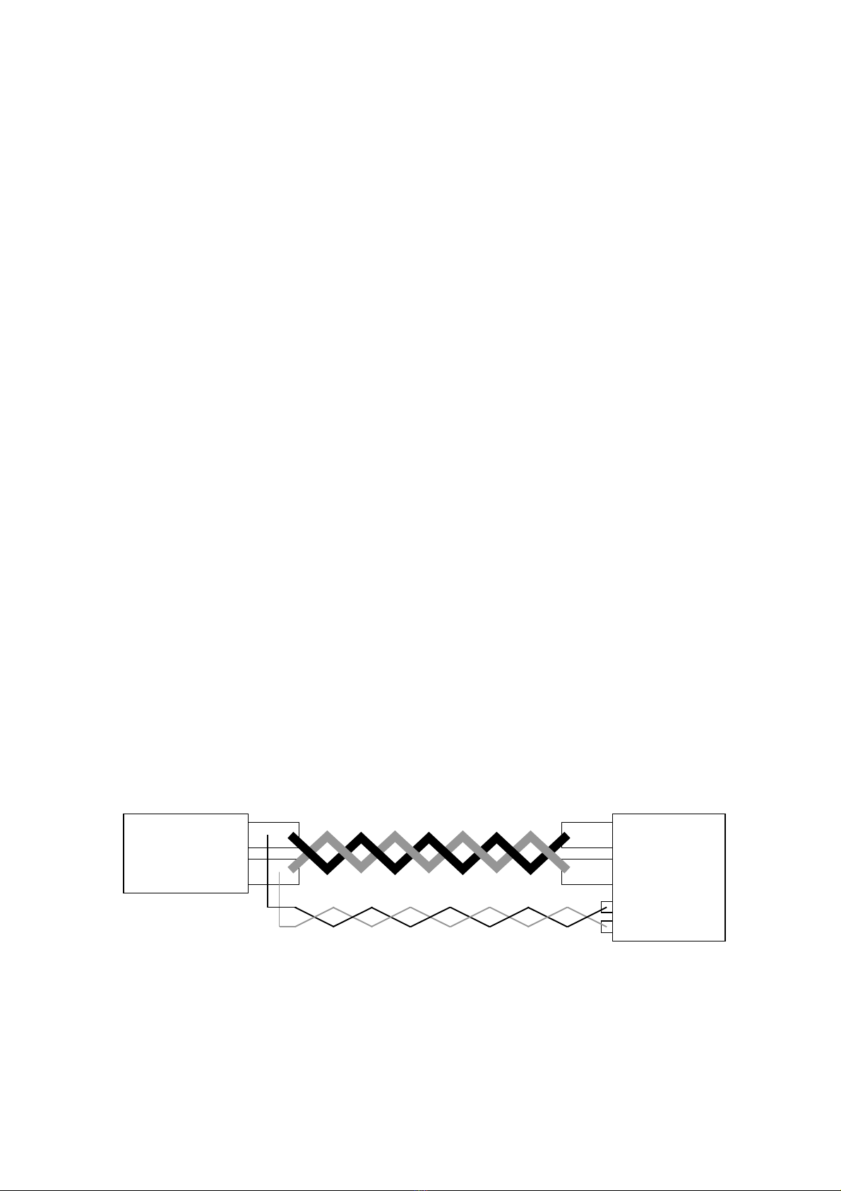
3-3 Instruction on Connecting Input Terminals
・This is a multi-input electronic loading unit. Each input terminal is available in the floating condition.
However, series connection of input terminals is prohibited.
・The input terminals of this unit are isolated from the casing. High voltage may be applied between
the casing and input terminals of the unit, depending on the installation condition of the power
supply. Be very careful.
・Be sure to turn off the main input of this unit when connecting the input terminals of the unit with the
power supply. Connect load wires that sufficiently withstand the input current to the LW unit
between the LW unit and power source. Use as short load wires as possible to minimize the
resistance of the load wires.
・When using the sensing function, be sure to connect the + sensing terminal with + input terminal
and the - sensing terminal with - input terminal of the same channel. Reverse connection or
connection with another channel may cause malfunctioning or breakdown. Do not uses
unnecessarily long sensing wires between the LW unit and power source.
Twist the load wires and sensing wires, as the necessity requires. Twisting the wires reduces the
influences of noises.
The
source
of an electric
power supply
+
-
LW
+
-

10
3-4 Installation Environment
・The allowable ambient temperature range when using this unit is 0 to 40℃. Do not use the unit at
ambient temperature out of this range. If the unit is used at high ambient temperature and the
built-in heat sink overheats, the internal overheat protector circuit works and an overheat alarm
(OHA) occurs, turning off the main input. Do not block the air vents in the front and top panels or
air outlet in the rear panel. Blocking them also causes internal overheat. Leave enough spaces
around the air vents and air outlet.
・Hot air is blown out of the air outlet in the rear panel of the unit. If an object easily damaged by
heat is placed behind the unit, it may possibly be deformed. If metal or the like is placed behind
the unit, it is heated by exhaust air (hot air) from the rear panel, resulting in burn. Do not place
any object (object easily damaged by heat, metal, etc., in particular) behind the unit. Leave a
space of 1.5 meter or more from the unit, if it is necessary to place some object.
・This unit has an air inlet in the front part of the top panel. Blocking the air inlet may cause
decrease of the performances, breakdown or OHA. Never block the air inlet of the unit.
・Leave a space of 44 mm or more above the unit in order to prevent the air inlet from blocking,
when the unit is mounted on a rack, etc. Also achieve a condition of preventing warm air in the
rack including exhaust air from flowing into the unit through the air inlet. (The rack must have no
rear covers.)
・Do not use the unit in a dusty place or a place with much corrosive gas. Dust or corrosive gas may
deteriorate the unit.
3-5 Current Limit Setting
・When the LW unit is used in a discharge mode other than the constant-current mode, large current
flows from the power source to the unit, depending on the output conditions of the power source
and setting of the LW unit, and the power source may become defective. Be sure to set the
current limit of the LW series when the LW unit is used in a discharge mode other than the
constant-current mode.
11
4. PANELS
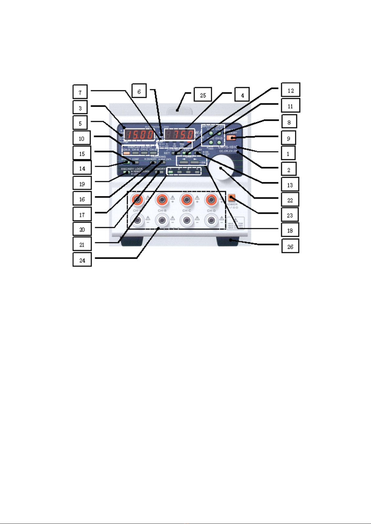
4-1 Front Panel
1. Model name
・One of the following model names is marked in this position.
LW75-151Q (75 W, 150 V, 15 A, four inputs), LW151-151D (150 W, 150 V, 30 A, two inputs),
LW301-151S (300 W, 150 V, 30 A or 60 A, one input), and LW75-151D (75 W, 150 V, 15 A, two inputs)
LW75-151Q
2. Discharge mode
・The discharge modes of the unit shown below are marked in this position.
(CC: constant-current mode, CR: constant-resistance mode, CV: constant-voltage mode, CP:
constant-power mode)
・This unit provides operations in the discharge modes marked in this position.
3. A display unit (red): Four digits
・Displays the input current, set value and function setting characters of a channel with the orange
DISCHARGE SELECT key lit.
4. V/W display unit (red): Four digits
・Displays the application voltage and power, set value, discharge mode, and function setting characters
of a channel with the orange DISCHARGE SELECT key lit.
This manual suits for next models
4
Table of contents
Other TEXIO Recording Equipment manuals


Popular Recording Equipment manuals by other brands

Ehong
Ehong EH-MC10 Command Interface User Guide

Force Dimension
Force Dimension omega Series user manual

Lab4Music
Lab4Music Sipario user manual

Extron electronics
Extron electronics SSP 7.1 user manual

Mitsubishi Electric
Mitsubishi Electric MAC-587IF-E installation manual

Yamaha
Yamaha MOTIF RACK Music System installation guide


