TF Model COBRA AH-1S 600 User manual

Required items for finishing this product
1. A comprehensive set of tools
2. CA glue
3. 30 minute epoxy glue
4. Trex 600 type mechanic, belt version
dry fitting of all the parts before assembly.
TF Model AH-1S 600
Thank you for purchasing TF Model's product, please read all
instructions carefully before proceeding with the actual assembly.
Some steps are required to be done first, so please do a complete

Recommended items for use in this product
1. TF Model 600 Slim tail gear box.
Wood Formers Assembly
4.Dry fit formers F-4A and F-4B halves into the
fuselage to the premarked line. Make sure the
formers fit flush and square to the
fuselage.The formers should sit behind the
rear landing gear hole. Once the formers are
aligned correctly, tack glue in place with a few
drops of CA glue.Use epoxy and securely glue
the former to the fuselage.
2.First glue the former F5 into the fuselage at
the tail joint location. Use photo for
reference.Once the former is glued in remove
the top section marked out by the cut lines.
1.Locate all the wood formers for the main
fuselage shown in the photo.
3.Glue former F3 to the front of the fuselage
as in the photo.

5.Another view of the formers F-4A and F-4B
6.Slide both landing gear cross memebers
through the fuselage holes.Now centre the
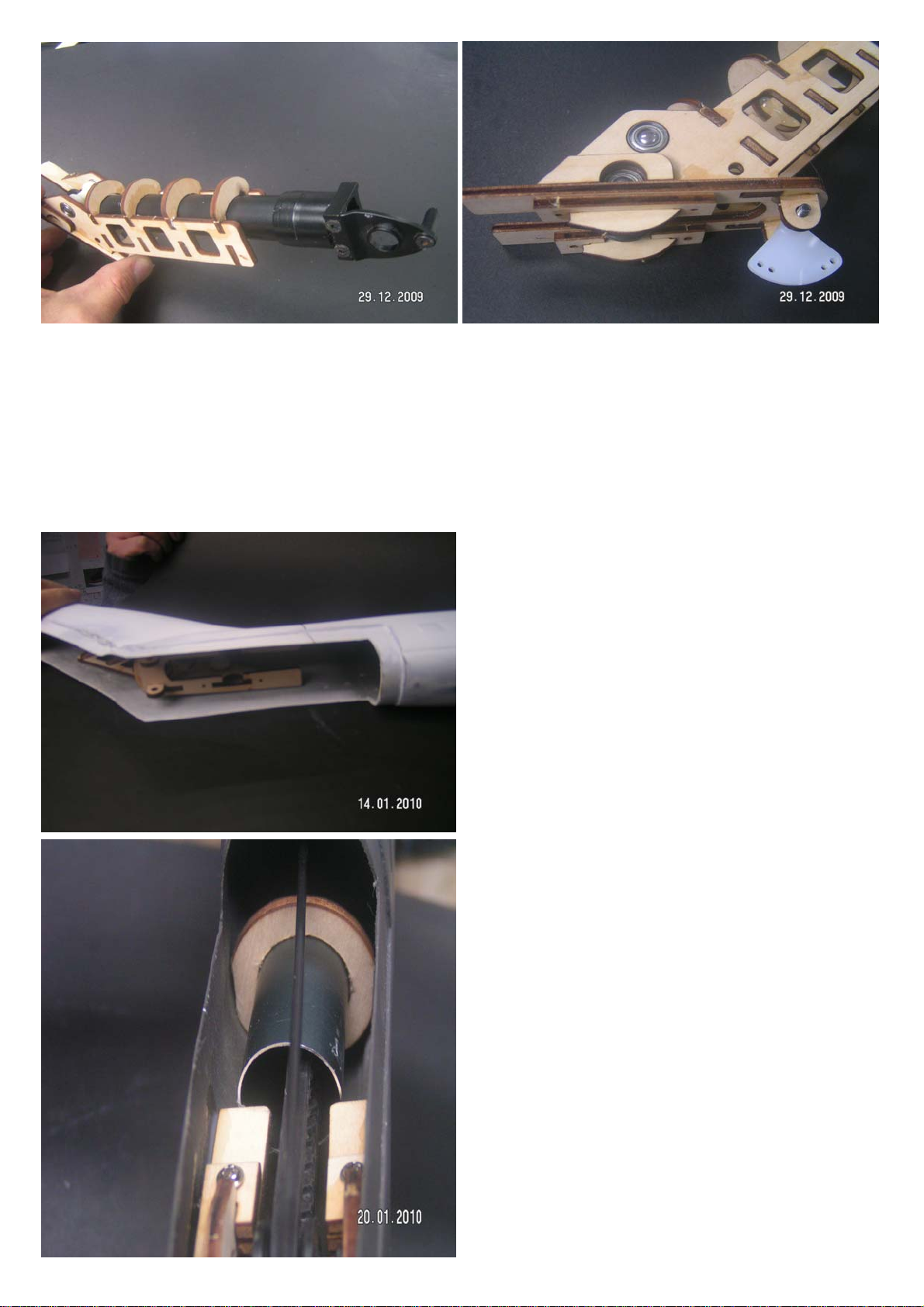
cross memember and tack glue in place with
CA glue.Use the predrilled holes in the cross
member as template and mark the 2 holes
onto the shims, do both the front and back
cross members.Drill 2mm diameter holes
through to the outside of the fuselage.Secure
the cross members with supplied 2 mm dia
screws and nuts.Insert the screw from the
bottom and the nuts on the inside for a flush
finish.
7.Once the screws are installed, epoxy the
landing gear cross member to the fuselage.
Do the front and rear corss members.Photo
shows the rear cross member.
8.Photo shows the front cross member.

9.Landing gear cross member screws. Screw
from the outside in for a flush finish on the
exterior.
10.Insert the landing gear plastic "T"s onto the
cross members' ends and insert the landing
skids through them. Once the landing gear is
squared, tack glue the skids and cross
members to the plastic "T". Drill 1 mm holes at
the location shown in the photo and secure
the landing gear skids with screws.
Rudder Sevo Mount Assembly
11.Locate the wood rudder mount and glue
them together as in the photo.
12.Glue the servo mount into the position
shown in the photo.Do this before joining the
fuselage halves for ease of assembly.You can
install the rudder servo at this time as well.

THE FOLLOWING STEPS FOR TREX 600 VERSION ONLY
13.The rudder servo mounting location viewed
from the inside.
14.Locate the fuselage wing area doubler in
the photo.
15.Next locate the wing stub outer
reinforcement ring and glue it to the outside
fuselage. The ring should align with the stub
wing outline. Once the glue has dried, use a
Dremel to open up the wing stub hole until
flush with the inside of the wood wing stub
reinforcement ring.The 4 circles are magnets
holding the former in place for gluing only.

16.Now glue the wing area doubler to the
inside of the main fuselage. Note the location
of the reinforcement panel in the photo. The
wing hole in the fuselage should sit inside the
doubler hole on all sides.If the doubler
interferes with the rear landing gear cross
member,trim the doubler's corner until it
fits.Do both sides of the fuselage insides.
17.Fit the mechanics inside the fuselage, take
off the rotor head and fit the top cover onto
the fuselage temporarily. Move the mechanics
until the main shaft is centered in the hole.
Mark the location of the 4 mounting holes and
drill the 4 3mm dia. holes on the fuselsage
bottom.
18.Use the holes for reference and glue the
wood mechanics shims onto the fuselage
bottom, covering the mounting holes. Use 3
shims for both the front and rear mounting
points.After the glue has set drill through the
wood shims from the outside bottom of the
fuselage, using the already drilled holes as
template.Use of 3 shims will put the main gear
centered in the wing hole on the sides of the
fuselage. Adjust height further by using
washers if needed.Spin the main gear to make
sure that it does not rub against the sides of
the fuselage.Once all is correct install the
mechanic into the fuselage using 4 bolts and
lock nuts.

19.Photo shows the completed front and back
mechanic shims.
20.Now join the front and rear fuselage halves
using epoxy glue. Align the joint line
accurately before gluing.
Wire Mesh Assembly
21.Cut the supplied wire mesh slightly larger
than the openings circled in the photo and
glue the mesh from the inside with epoxy.
Also glue in the exhaust cone into the rear
opening at this time.

Once all the shims and mechanic mounting holes are done, install the mechanic into the
fuselage.Due to the scale proportion of the Cobra, the fuselage is slim to scale and when
installing the mechanic you need to carefully spread the sides of the fuselage in order to
allow the mechanic to slip into the fuselage.
Once the mechanics is fitted inside, secure the mechanic using bolts screwed in
from the bottom and secured with nuts on the inside.
Installing the Mechanic
Elbow Gear Box Assembly
22.Locate the parts for the elbow bear box in
the photos.
23.Glue the pulley wheel doubler onto the
outside of the elbow gearbox side frames.
Align the circular cut out as in the photo. Do
both sides.Photo shows the outside face of
the elbow gear box side frame.

24.Install the bearing for the tension wheel
and insert the tension wheel into the bearing.
Also glue in the rear wood cross members at
this time.Use epoxy glue for this.
25.Glue the other side frame onto the cross
members and glue on the elbow gear box
base. Then glue the rudder bell crank support
onto the base. Use photo for reference while
assembling.Use epoxy glue for this.Assemble
the pulley wheel and its bearings and
assemble the bearing brackets. Again use
photo as reference. Dry fit the pulley wheel
assembly into the bearing slot,use supplied
plastic spacer to shim the pulley wheel and
the bearings for a snug fit in the bearing slot.
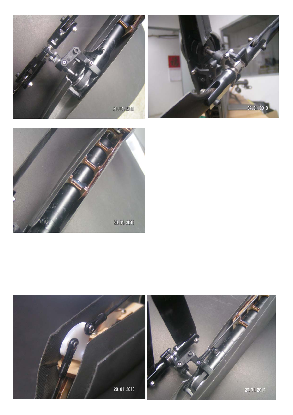
26.Install the rudder bell crank to the bell
crank support at the base board. Make sure
that the bell crank can turn smoothly and
freely. Adjust the bell crank smoothness by
the tightness of the screw.
27.Insert the pully wheel assembly into the
bearing slot and screw in the bearing brackets
to hold the pulley wheel assembly in place
temporarily.
31.After cutting the tail tube to length and
lining up the tail tube with the elow gear box
base board, slip the wood tail tube fixing
former onto the tail tube and slide it up the tail
tube. Trim the wood fixing if necessary for
centering the tail tube. The tail tube does not
have to touch the base board.After the
location of the wood tail tube is correct, glue
the former to the fuselage ONLY. DO NOT
GLUE THE TAIL TUBE TO THE FORMER AT
ANY TIME.Now slide the vertical tail tube into
the elbow gear box assembly, do not glue the
tube yet, and glue the elbow gear box aood
frame to the fuselage using epoxy.
28.Temporarily insert the supplied tail tube
against the rear cross member and use it as a
jig for gluing the front cross memebers. Tacky
glue the front cross members in place,
remove the tail tube, then glue with epoxy.
29.Photo shows the completed assembly
before inserting into the fuselage tail.
Elbow Gear Box Insertion.
30.Slide the elbow gear box assembly into the
tail fin for dry fitting. Install the mechancis
with tail tube. Note the length of the tail tube
to cut off to allow fitting of the elbow gear
box.Try to line up the elbow gear box base
with the tail tube centre line. Please pay
attention to the following photo for better
understanding of the relationship of the elbow
gear box and the tail tube.

32.Remove the pulley wheel bracket and
remove the pulley from the elbow gear box
assembly base board. Pull the timing belt
through, note the direction of the belt. Install
the pulley wheel through the belt and back
into the base board,and reinstall the pulley
wheel brackets and screw them in place.Pull
the belt through the vertical tail tube. Again
note the orientation of the belt.
33.Disassemble the tail gear box and slip the
locking collar part of the tail gear box onto the
vertical tail tube. Pull the belt through.Install
one side of the tail gear box side frame and
pull tight on the belt with your finger.
Estimate the approximate location of the tail
rotor shaft and mark the corresponding
location on the tail for removal of parts of the
tail area to fit the tail rotor and rudder pitch
bell crank. Patiently remove material for a
nice snug fit, checking the fit frequently and
removing material little at a time.Be sure to
allow for tension adjustment of the tail gear
box after the first flight.Please refer to the
following group of photos for reference.
34.After completing the above step, you can
now glue the tail tiube to the elbow gear box
wood frame using epoxy.
Now install 2 ball links to the bell crank in the photo and connect the push rod
forwards to the rudder servo and backwards, up along the vertical tail tube to
the rudder pitch bell crank at the tail gear box. Refer to the following group of
photos.
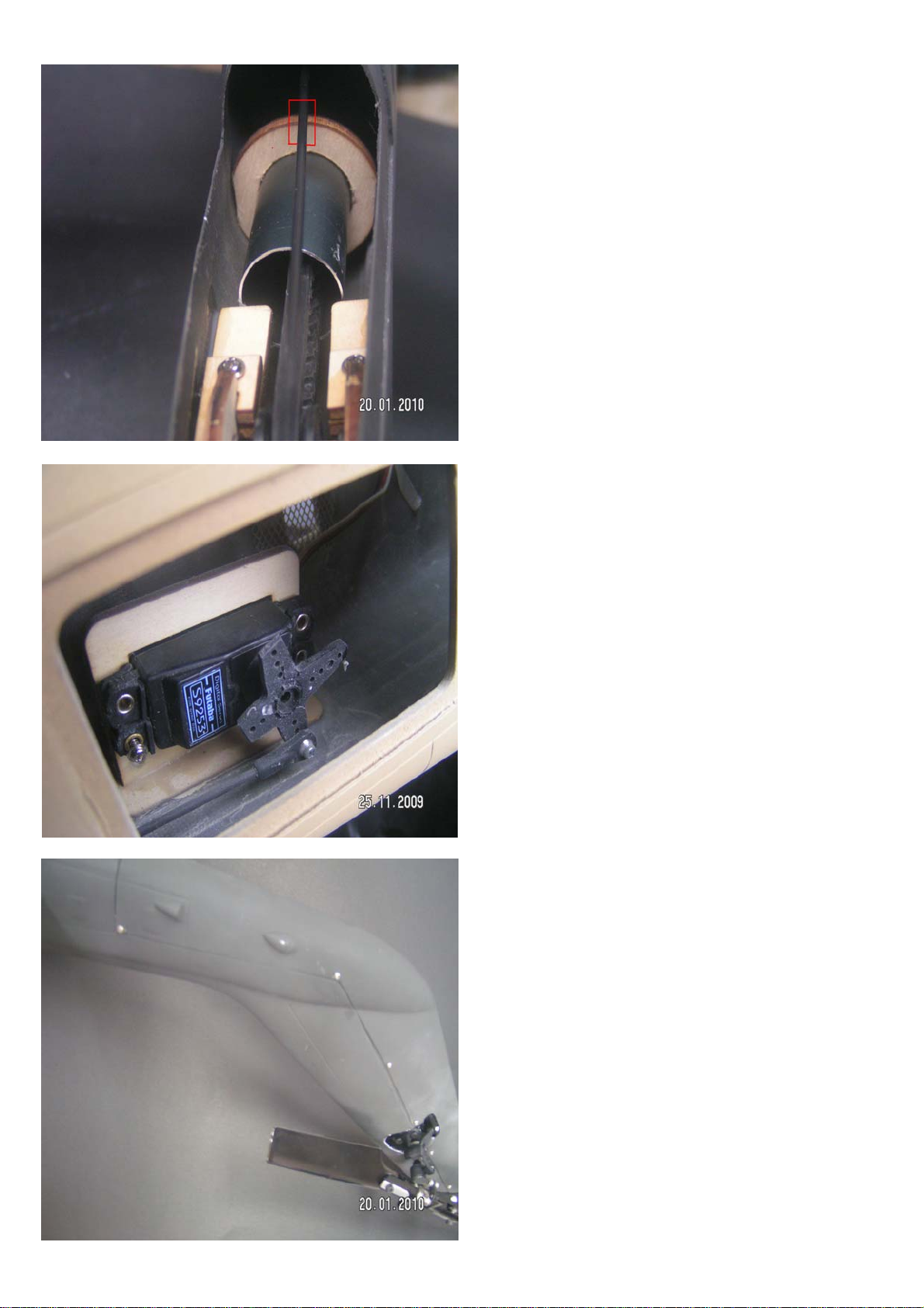
37.After checking that the bell crank and
rudder is operating smoothly and correctly, fit
the tail cover on and drill 1 mm diameter
holes for the fixing screws on both sides.
35.We recommend that you glue a push rod
support at the location indicated.
36.Connect the push rod to the rudder servo.
Before connecting please power up the
receiver and transmitter and centre the rudder
servo.
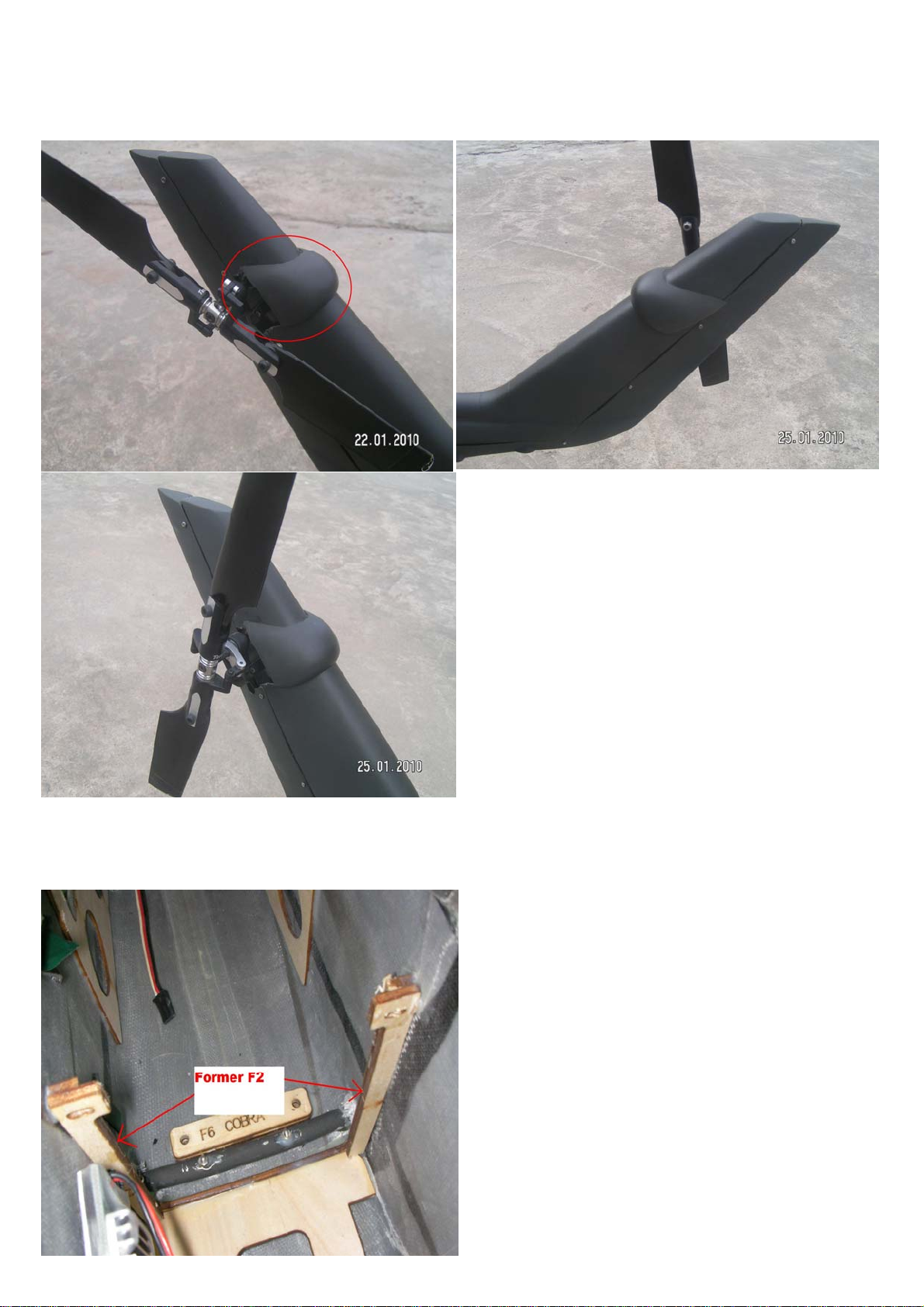
38.After installing the mechanics inside the
fuselage, dry fit formers F2 in front of the front
landing gear making sure that it does not
interfere with the mechanic and anchillary
equipments. Once the location is determined,
glue formers F2 (both left and right sides) into
place.
Now locate the tail rotor cover and trim it to fit the tail rotor location as in the
following group of photos. Once the fitting is correct, glue into place.
Front Cross Member Former Assembly

39.Locate cross brace former F7 and the
fuselage stays anchors. Use bolts and nuts to
attach the cross brace to formers F2.
40.Carefully study the installation of the cross
brace and the mounting of the fuselage stays
in the photo, using it as reference.
41.Now proceed to gluing the battery tray to
the floor on the front part of the fuselage in
front of formers F2.

Upper Front Cover Assembly
Fit the upper front cover onto the main fuselage and use clamps to achieve a
flush fit on all sides. Once flush fit is achieved mark and drill 4 fixing holes
on both inside lips. Glue 4 pegs on the upper front cover and fit in on to the
upper main fuselage. Trim the 4 holes on the main fuselage section to again
achieve a flush fit. After a flush fit of the 2 parts are achieved use screws to fix
the 2 parts together.Refer to the following group of photos.
42.4 fixing pegs.
43.4 corresponding holes for the fixing pegs
on the main fuselage section.

Canopy and Cockpit Assembly
44.Use screws to fix the 2 parts.
Glue the supplied canopy lock on the rear inside of the canopy frame.
Dry fit the clear windows onto the canopy frame and glue them
on the inside using silicone glue or canopy glue.
Tack glue the cockpit support frame to the inside of the canopy frame first,
fit the canopy frame onto the fuselage and check for a flush fit. If the cockpit
frame is too low in the canopy framethe canopy frame will not sit flush with
the fuselage.Adjust the height of the cockpit support frame to achieve a
flush fit. Glue the cockpit support frame to the canopy frame
glue in the fixing tongue as well.
canopy lock.Now glue in the front canopy frame wood support and also
Trim the cockpit little at a time for a flush fit. Once a flush fit is achieved,
cockpit and slide it in between the canopy frame and cockpit support.
With the cockpit support frame glued in, trim the black vacuum formed
with epoxy once the correct height is set.
glue the cockpit to the support frame.Remember to trim the cockpit for the

45.Glue in canopy lock. Remember to centre
it.
46.Cockpit support frame.
47.View of cockpit support frame side.

48.Cockpit support frame and cockpit fitting.
49.Cockpit cut out for canopy lock.
50.Front canopy frame wood former and
fixingtongue.

51.You might need to glue a wood shim
indicated in the photo for the canopy lock to
work properly.
52.Canopy lock once assembled correctly.
53.Completed canopy.
Table of contents
Other TF Model Toy manuals


