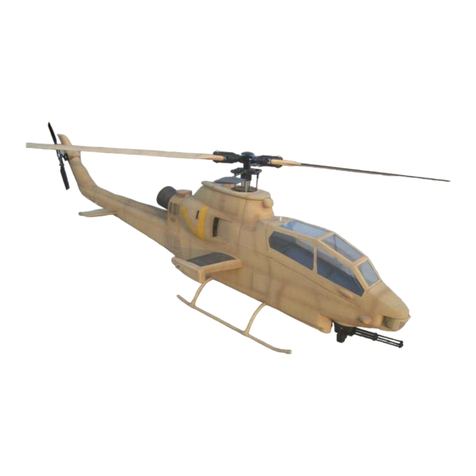
TF Model Apache 600 User manual

TF Model Apache 600 Manual
Thank you for purchasing TF Model's product, please read all instructions
carefully before proceeding with the actual assembly. Some steps are
required to be done first, so please do a complete dry fitting of all the
parts before assembly.
Required items for finishing this product
1. Sullivan Flexible Gold-N-Rod 48"
2. A comprehensive set of tools
3. CA glue
4. 30 minute epoxy glue
Recommended items for use in this product
1. TF Model 600 Slim tail gear box.
2. TF Model 600 4 Blade main rotor head

Wood Formers Assembly
Locate the wood formers in the kit
as in the photo.
Before proceeding to gluing the wood formers, you
need to first glue the front and the rear fuselage halves
together !
Glue in Formers
F 4 and F 5
Open up a hole in the wing stub location on the fuselage.
Fit the wing spar former through the wing stub hole.
Move the former around until the top and bottom of
the former sits tight against the sides of the hole.
Tack glue in place only, further adjustment will be made
after installing the mechanic.

Location of the wing former viewed from the inside.
Locate formers 3 in the former
pack and glue them to the inside
of the fuselage about 5 mm behind the
canopy opening.
After gluing the former F3 trial fit the baseboard
into the fuselage. Trim formers F 4 and F 3
to fit the base board. Make sure the baseboard is
centered. Do not glue the base board at this time.
Measure about 8 cm from the rear top
opening of the main fuselage. Mark the location.
This is the location where the main shaft sits.
Fit the mechanic onto the base board, line up the
4 mounting holes on the base board with the mounting
holes of the mechanic. Tack glue the base board onto
the mechanics. Hot glue gun works well.
Fit the mechanic and base board assembly into the
fuselage, move the assembly around until it is centered
and the main shaft is at the premarked location.
Once satisfied with the location, use a marker and mark the
outline and the 4 mounting hole locations on the inside
fuselage bottom. Drill the 4 holes from the inside out. Detach the
base board from the mechanic and glue it to the fueslage. Make
sure that the 4 mounting holes on the base board, aligns with the
4 holes in the fuselage bottom.

For long length motors, a hole needs to
be made at the motor location. The photo
shows the location for the use of Align motors.
If you are using Logo mechanics or a different
motor other than Align, you can leave the hole out.
However, for hot climates we recommend at
least a smaller diameter hole for motor cooling.
Landing Gear Assembly
Locate the Landing gear A arm support
in the former
First assemble the A arm support and
glue to the inside of the fuselage.
The top of the A arm support should align
with the mounting location for the top of the
landing gear strut.
Proceed on to opening up the holes
for the landing gear struts.

Open up an rectangular hole on the
top of the sponson for the landing
gear strut to go through.
The approximate dimension is
24 mm long and 14 mm wide.
The bottom hole for the landing gear strut
is approximately 54 mm long and 17 mm wide.
Drill through and mount the top landing
gear strut first. Insert the lower gear strut through the
bottom hole. Screw the lower strut to the aluminium
landing gear cross member on both sides.
Move the assembly around until a desired angle of
the landing gear is achieved. Tack glue the cross member
in place. Do a final alignment check, then drill 2 holes
from the inside, using the 2 holes on the alum. cross
member as template. Secure the cross member using
screws and bolts supplied in the landing gear parts bag.

Once the landing gear has been installed check
for clearence and the operation of the landing gear
compression.
Elbow Gear Box Assembly
Locate the elbow gear box formers and parts bag.
Push out all the Laser cut wood parts and lightly
sand the edges to prepare them for assembly.
Start by assembling the bottom assembly of
the elbow gear box. Note that all parts
are arranged in alphabetical order.
Use Epoxy glue here.

Glue the top plate onto the frame work.
Bottom elbow assembly complete.
Assemble the upper elbow gear box assembly as
in the photo.
Locate all parts for the tension wheel and pulley wheel.
Please note that the pulley wheel requires 3 shims on each
side, between the wheel and the bearing.

Install the tension wheel and pulley wheel into the upper elbow
assembly.
Slide the upper elbow assembly into the complete
lower elbow assembly. Please note the white tension
wheel should be on top and the black pulley wheel
should be on the bottom.
Familiarize with the attachment of the top elbow gear
box and the bottom part of the gear box. The 2 assemblies
interlocks. Push the rear flanges into the long holes in the
bottom asembly and slide forward to lock. When assembly
is correct it will look like the photo. At this time DO NOT GLUE
the 2 assemblies together. Take them apart and proceed to the
next step.

Slide the top elbow assembly into the fuselage tail from
the bottom as in photo.
View from the bottom.
Now slide the lower elbow gear box assembly
into the tail from the rear forwards. Note
that the rounded part faces the bottom.

Now combine the upper and lower elbow gear box
assemblies and interlock them together as you
did in the dry fit/trial run in the earlier steps.
Another view showing the correct
interlocking position of the upper
and lower elbow assemblies.
The front of the upper assembly should contact
the lower assembly in the front like in the photo.
Once all fits snug, glue with epoxy the 2 assemblies.
Omly glue the 2 assemblies together, do not glue the
assemblies to the fuselage at this time.

Now slide the whole assembly forward
until the upper assembly is all the
way forward in the tail fin and will
not go any further.
Insert the supplied 20 mm dia tail tube into
the space between the fuselage and the upper
elbow assembly.
Do not glue at this time.
Locate the bearing bracket assembly as in the
photo and glue them together. Do 2 sets.
Set these aside for the time being.

Glue the circular rear landing
gear bearer to the inside of the
tail cover.
Offer up the tail cover to the rear
of the fuselage and push it in until
it is a nice flush fit. When the tail cover is all the
way in push the elbow assembly from the inside
until it rests against the tail cover inside wood
rear landing gear bearer.
Slowly remove the tail cover without
disturbing the elbow assembly, then tack
gluethe elbow assembly to the fuselage with
a few drops of CA.
Mechanic Installation
Before mounting the mechanics, locate the included
side frames. Dismantle the bearing blocks and the
plastic base plate and the tail boom holder from
the stock Trex mechanic. The aileron and elevator
bell cranks are not used, so do not dismantle them
from the stock frame and put them aside.
The lower side frame in the kit uses direct CCPM
drive, so you will need to set up new swashplate
pushrods.

photo shows the completed low rider side frames
Close up of the low rider side frame pushrod layout.
Slide in the mechanics from the front canopy
opening. You night need to spread the sides carefully to
do this. Once the mechanics is in, mount the mechanic
temporarily using 4 screws. Push the 4 screws in from
the bottom of the fuselage and use tape to hold them in place.
Do not bolt them in at this time.
You can use the supplied wood shims to achieve your desired
height and angle of the swashplate and mainshaft. The prototype
use one wood shim in front and none at the back.

Turn over the fuselage and check the elbow
gear box area at the back. You will need to cut the length
of the tail boom so that the end of it will sit at the
approximate location as in the photo.
If not, adjust the location of the elbow gear box to achieve this.
Once the fit is correct re tack glue the elbow assembly in place with
a few spot of CA glue.
IMPORTANT ! After retacking the elbow assembly fit the
tail cover to ensure the fit is correct !
Pull the belt through the tail tube and put the
pulley wheel inside the belt loop and push the
pulley wheel with bearings into the bearing
holder slot. Note belt direction.
Screw in the bearing brackets.
Proceed to pull the belt through the 20
mm dia. tail tube.
Do not glue the tail tube yet.
Install the tail gear box onto the 20 mm dia
tail tube. And hook the belt up to the tail gear box
pulley wheel.
Photo shows the TF Model 600 tail gear box.
Slide the rudder push rod outer sleeve down
the front of the tail tube at the location shown in the photo.
Run the push rod outer sleeve all the way up to the front
of the cockpit area. Tape the ends inside the
fuselage temporarily.

Use the hole in the top fin as a reference and
adjust the height of the tail rotor by sliding
the tail tube up and down. You need to be
aware of the belt tension at the same time.
Fine adjustment of the belt tension can be
done by sliding the tail gear box (This
adjustment is only possible if you use
TF Model's metal tail gear box, available as
an option).
After finalising the adjustment of the tail rotor/gear box
location, open up the bottom of the tail rotor hole to allow
the fin top to slide onto the lower fin.
Drill 4 1.5 mm holes for fixing the top fin to
the bottom fin. You decide the best location for
the fixing screws.
Rudder Control Rod Installation.
Take out the mechanics again, leaving the rudder
push rod outer sleeve inside the fuselage.
Now use thin CA and a few drops of epoxy, glue
the push rod outer sleeve to the inside of the
fuselage.
The photo shows the recommended mounting location
for the rudder servo.
Insert the rudder pushrod through the sleeve and measure
and cut the pushrod and the sleeve outer to length
according to the location of the servo.
For the push rod we recommend that you use
Sullivan gold N rod 48 " length.

Another view of the recommended location
of the rudder servo.
After cuttung to length, follow the Sullivan
push rod's instructions for mounting.
Mount the tail rotor side first.
Connect the servo to the gyro and to the
receiver, power up the receiver and set the
neutral position of the rudder servo.
Once you are satisfied with the neutral position,
mount the push rod to the rudder servo.
We recommend that you mount the Gyro at a
remote location for easier access for adjustments
later.
Now install the mechanic into the fuselage and fix
it to the fuselage with 4 M3 screws from the bottom
through the previously drilled holes.
Gluing the Tail Elbow Gear Box Assembly to the
Fuselage
With the fuselage secured to the
fuselage as in the above step,
reassemble the tail gear box and
the rudder pushrod. Adjust the belt
tension by pulling on the tail tube with
tail gear box assembly until it is correct.
The correct tension is tight but with
a little give when you push down on the
belt.
Once the correct tension is achieved,
tack glue the tail tube to the wood
elbow frame with CA glue to
maintain belt tension, then use epoxy
to glue the tube and fuselage.
Future adjustments of belt tension
can be done by adjusting the tail
gear box ( Only possible with TF Model's
optional metal tail gear box).

Test fin the top fin for final fitting,
opening up the hole until a good fit, with
out binding of the tail rotor operation
is achieved.
Once all is secured to the fuselage,
use the supplied fuselage stays to secure the top of
the fuselage.
The photo shows one possible way of the use and location
of the fuselage stays.
Now fit the tail cover on and drill
holes for fixing screws.

Offer up the rear landing gear assembly to
the rear tail cover, center it and mark the
mounting screws' location using the gear's
circular base as a template. Drill the 3 holes
and use wood screws supplied to fix onto the
tail cover. The screws should screw through
to the elbow assembly as well.
Ancillary Parts Assembly
Slide the wings onto both wing spars that were glued earlier in
the wood former stage. Dry fit the wings for a snug fit against
the fuselage sides. Carefully open up the wing root hole until
a satisfactory fit is achieved.
The finished wing should look like the one
in the photo.

Locate the engine nacelle parts in the photo.
Dry fit the nacelle intake to the main nacelle body.
The intake is handed and will only fit correctly in one
way.The protrusion in the nacelle body needs to align
and fit with the protrusion on the intake part.
Mark and trim the intake for a flush fit with the nacelle
body.
Study the photo carefully and dry fit the nacelle assembly
onto the fuselage sides. Use a pencil and mark the location
of the nacelle for gluing to the fuselage. Please note the nacelle
has a left and right side. Glue both nacelle assemblies to
the fuselage.

The photo shows the location of the FOD screen.
There is a left and right FOD screen. Please use photo
for reference and do a dry fitting before gluing theFOD
screen to both the fuselage side and the intake.
Note that the indentation faces forwards.
The completed engine nacelle assembly
with the FOD screen.
Locate the front sightimg system parts as in the photo.
Table of contents
Other TF Model Toy manuals
Popular Toy manuals by other brands

Walkera
Walkera QR X350PRO quick start guide

Radica Games
Radica Games 75058 instruction manual

John Adams
John Adams GLOWPAD Studio quick start guide

Multiplex
Multiplex MULTIGyro G3 instruction manual

Horizon Hobby
Horizon Hobby SPARC! HVR 062 owner's manual

vario helicopter
vario helicopter AH-1S Cobra manual